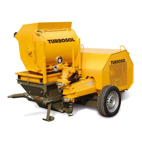
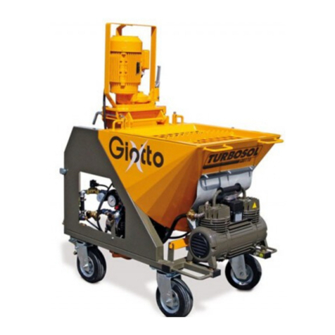
Turbosol GIOTTO MONO User manual

Serial number Year
USE AND MAINTENANCE MANUAL
GIOTTO MONO
IS16/02 - 561379
EN
ORIGINAL

THIS MANUAL IS PROPERTY OF TURBOSOL - ANY TOTAL OR PARTIAL REPRODUCTION IS STRICTLY FORBIDDEN

THIS MANUAL IS PROPERTY OF TURBOSOL - ANY TOTAL OR PARTIAL REPRODUCTION IS STRICTLY FORBIDDEN
INDEX
1 - CE DECLARATION..................................................................................................5
1.1
CE DECLARATION OF CONFORMITY........................................................................................5
2 - GENERAL INFORMATION ......................................................................................7
2.1
IMPORTANCE OF THE MANUAL.................................................................................................7
2.2
ABBREVIATIONS..........................................................................................................................7
2.3
INFORMATION FOR CONSULTING THE MANUAL....................................................................7
2.4
DESCRIPTION OF THE SYMBOLS..............................................................................................7
2.5
STATUS "MACHINE OFF .............................................................................................................8
2.6
GENERAL AND CONTACT INFORMATION................................................................................8
3 - TECHNICAL DESCRIPTION....................................................................................9
3.1
NAME OF MACHINE.....................................................................................................................9
3.2
DIMENSIONS OF MACHINE.......................................................................................................10
3.3
TECHNICAL DATA......................................................................................................................10
3.4
INTENDED USES ........................................................................................................................10
3.5
PRODUCTS USED FOR PROCESSING.....................................................................................11
3.6
NAME OF COMPONENTS..........................................................................................................12
4 - TRANSPORT AND HANDLING .............................................................................13
4.1
TRANSPORT...............................................................................................................................13
4.2
LIFTING .......................................................................................................................................13
5 - INSTALLATION......................................................................................................15
5.1
PLACEMENT ...............................................................................................................................15
5.2
HOSES.........................................................................................................................................16
5.3
COUPLINGS................................................................................................................................16
5.4
CONNECTIONS...........................................................................................................................17
6 - SAFETY..................................................................................................................21
6.1
SAFETY DEVICES USED............................................................................................................21
6.2
SAFETY SIGNALS ......................................................................................................................22
LABEL 22
DESCRIPTION..............................................................................................................................................22
6.3
PERSONAL PROTECTIVE EQUIPMENT...................................................................................23
MANDATORY SIGNS ...................................................................................................................................23
DESCRIPTION..............................................................................................................................................23
6.4
RESIDUE RISKS..........................................................................................................................24
6.5
SAFETY WARNINGS ..................................................................................................................24
7 - USE AND OPERATION..........................................................................................25
7.1
OPERATING PRINCIPLE............................................................................................................25
7.2
PUMPABLE MATERIALS ...........................................................................................................25

THIS MANUAL IS PROPERTY OF TURBOSOL - ANY TOTAL OR PARTIAL REPRODUCTION IS STRICTLY FORBIDDEN
7.3
CHECKS BEFORE SWITCH-ON ................................................................................................26
7.4
CONTROLS.................................................................................................................................28
7.5
MACHINE SWITCH-ON...............................................................................................................29
7.6
CLEANING AND END OF WORK...............................................................................................31
7.7
REPLACING THE PUMPING UNIT.............................................................................................33
7.8
IMPORTANT WARNINGS...........................................................................................................34
8 - MAINTENANCE......................................................................................................37
8.1
OPERATOR RESPONSIBILITY..................................................................................................37
8.2
QUALIFIED PERSONNEL RESPONSIBILITY............................................................................37
9 - DEMOLITION .........................................................................................................39
9.1
MAIN WARNINGS .......................................................................................................................39
10 - TROUBLESHOOTING .........................................................................................41
10.1
MATERIAL DOES NOT COME OUT OF THE GUN...................................................................41
10.2
BLOCKING THE PUMP...............................................................................................................42
10.3
FUSES/OVERLOAD CUTOUT TRIPPING..................................................................................42
10.4
OTHER PROBLEMS ...................................................................................................................42
10.5
OPERATOR INTERVENTION .....................................................................................................43
11 - OPERATOR RESPONSIBILITY...........................................................................45
11.1
RESPONSIBILITY .......................................................................................................................45
11.2
WARRANTY.................................................................................................................................45

CE DECLARATION
1
561379 - IS16/02 - EN
5/46
1 - CE DECLARATION
1.1 CE DECLARATION OF CONFORMITY
An original copy of the CE Declaration of Conformity is supplied separately from the manual.

1
CE DECLARATION
6/46
561379 - IS16/02 - EN

GENERAL INFORMATION
2
561379 - IS16/02 - EN
7/46
2 - GENERAL INFORMATION
2.1 IMPORTANCE OF THE MANUAL
This "Use and Maintenance Manual" has been drawn up following the guidelines envisioned in the relevant European
Directives in order to guarantee simple and full understanding of the subjects by the operators authorised to operate
and perform maintenance on the machine in question. The manufacturer has prepared this manual with the greatest
care. However, should any operators find any part of the manual difficult to understand, they should contact the
manufacturer immediately and request explanations and/or further information in order to avoid misunderstandings
that might compromise the user's safety. Before using the machine, authorised operators must read and understand
this "Use and Maintenance Manual" in every part and strictly follow the Standards herein, in order to ensure their own
safety and that of others, to make the machine work at its full potential and to ensure a long-lasting and efficient
service life to all the machine parts. This manual should be safely stored and kept close to the machine at all times for
immediate consultation by operators.
Only specifically trained and authorised staff can operate and perform maintenance on the machine.
Operators must follow all the instructions regarding the prevention of accidents and the regulations on workplace safety in force
in the country of use.
The Manufacturer shall not be responsible for any damages resulting from changes made arbitrarily to the machine.
Users are advised to take note of the machine’s serial number; it must be presented along with every request for technical
assistance or for spare parts, and will facilitate processing such requests.
This manual reflects the latest information available at the time of marketing the appliance and should not be considered
inadequate only because it may be successively updated on the basis of newly acquired information.
Reprinting or reproducing this manual, in whole or in part, is not allowed unless authorized by ourselves in writing.
THE MANUFACTURER DECLINES ANY RESPONSIBILITY FOR DAMAGES TO PERSONS, ANIMALS OR PROPERTY
CAUSED BY FAILURE TO OBSERVE THE STANDARDS AND RECOMMENDATIONS CONTAINED HEREIN.
2.2 ABBREVIATIONS
ca. around min minutes
cap. chapter N. number
DPI device of individual protection pag. page
DX right par. paragraph
h times pos. position
EN European Norm RIF. reference
Es. example s second
FIG. figure SX left
max.
maximum TAB.
table
min. minimum v. see
TAB.01
2.3 INFORMATION FOR CONSULTING THE MANUAL
Boldface:
Highlights important parts in the text.
2.4 DESCRIPTION OF THE SYMBOLS
Information and recommendations that are particularly important are indicated in this manual by the following symbols:
ATTENTION: this symbol indicates safety regulations regarding the operator.
PRECAUTION: this symbol indicates the possibility of causing damage to the machine and/or its parts.
IMPORTANT NOTE: this symbol supplies useful information.

2
GENERAL INFORMATION
8/46
561379 - IS16/02 - EN
2.5 STATUS "MACHINE OFF
Before performing any type of maintenance and/or regulation on the machine, it is mandatory to isolate the electric power
supply. Disconnect the electric cable, make sure that the machine is effectively off, make sure that there is no residual pressure
in the piping (On trampling the pipes must go limp) and that the line manometer indicates zero bar.
2.6 GENERAL AND CONTACT INFORMATION
The ready/mixed plastering machine can be supplied in different set-ups and with different accessories, therefore it is not said
that all components described in this manual are mounted on your machine.
The Customer Service department of Turbosol Produzione S.p.A. will be glad to provide any information you may need.
Turbosol Produzione S.p.A.
Via Volta, 1
31030 Pero di Breda di Piave (TV) - ITALIA
Tel. +39 - 0422 - 90.2.51
Fax +39 - 0422 - 90.44.08
website: www.turbosol.it
e-mail: [email protected]
TURBOSOL MACHINES
They are the result of years of experience and constant research. The "know how" acquired in this way, along with great
attention to quality, constitutes the fundamental guarantee for the manufacturing of machines with long duration, great reliability
and reduced management costs.
MAINTENANCE AND CARE
Proper maintenance and care are essential for the machine to work as designed. It is therefore extremely important that users
respect the recommended maintenance intervals and carry out any maintenance required, both to keep the machine in perfect
running order and to preserve the validity of the warranty.
SAFETY
All service staff must be informed of the Safety Standards. The general Standards relative to safety and accident prevention
envisioned by local legislation must also be complied with.
OPERATOR TRAINING
The operator must receive specific training regarding the operations to be carried out.
Turbosol periodically carries out training courses, also on specific request of the customer.
TURBOSOL SERVICE
Please contact your TURBOSOL dealer for any information regarding machine malfunctions or requests for spare parts.
Turbosol Produzione S.p.A. reserves the right to make any technical modification for machine improvement, even if not
contemplated in this manual. Some drawings and representations may be indicative.

TECHNICAL DESCRIPTION
3
561379 - IS16/02 - EN
9/46
3 - TECHNICAL DESCRIPTION
3.1 NAME OF MACHINE
CE mark plate
123
kg
FIG.01
The machine's series (1), model (2) and serial number (3) are engraved on the nameplate, as well as its power rating.
The meaning of the symbols used are as follows.
(1) = Machine series:
(2) = Machine model:
(3) = Machine serial number.
Position of the CE mark plate
The CE mark plate (FIG. 02-REF. 1) is affixed to the mixer chamber.
Position of the machine serial number
The machine's serial number (FIG. 02-REF. 2) is punched onto the mixer chamber as well as on the nameplate.
1
2
FIG.02

3
TECHNICAL DESCRIPTION
10/46
561379 - IS16/02 - EN
3.2 DIMENSIONS OF MACHINE
The following are the machine's overall dimensions and gross weight (in working conditions).
LENGTH WIDTH HEIGHT WEIGHT
1.150 mm 650 mm 1.470 mm 250 kg
TAB.02
3.3 TECHNICAL DATA
Type of power supply - Single-phase
Power voltage V 230
Power supply frequency Hz 50
Control circuit power supply V 24 AC
Installed power kW 4.37
Pneumatic circuit set pressure bar 2
Hydraulic circuit pressure reducer set pressure bar 2
Maximum granulometry processable (with D5 2.5 ECO pump) mm 5
Delivery distance (approximate) m 15
Hopper capacity l 110
Permissible environmental temperature °C 0° ÷35°
Guaranteed sound power level LwA dB 101*
Guaranteed sound pressure level LpA dB 78
Mortar pump gear motor
Power kW 3
Performance 1° l/min-rpm 12-225
2° 14.5-270
3° 18-300
Dispenser gear motor
Power kW 0.25
Speed 1° rpm 6
2° 7.5
3° 9
Water pump
Power kW 0.6
Flow rate l/min 45
Head m 43
Pressure switch set pressure bar 1.5
Compressor
Power kW 0.52
Flow rate l/min 210
Maximum pressure bar 4
TAB.03
* The operator must use Individual Protection Devices (IPD) for hearing.
3.4 INTENDED USES
The machine has been designed and built for the following use:
FIELD OF USE: construction sector.
DECLARED USE: conveying and spraying ready-mixed plasters.

TECHNICAL DESCRIPTION
3
561379 - IS16/02 - EN
11/46
3.5 PRODUCTS USED FOR PROCESSING
Cement or gypsum based dry ready-mixed products. GIOTTO is not suitable for processing traditional mortars.

3
TECHNICAL DESCRIPTION
12/46
561379 - IS16/02 - EN
3.6 NAME OF COMPONENTS
FIG.03 shows the illustrations and names of the main components that make up the machine.
5
10
4
7
3
9
2
1
13
11
6
12
8
FIG.03
KEY:
1) Frame
2) Hopper
3) Protection grid
4) Main gear motor
5) Mixing chamber
6) Mixer
7) Dispenser
8) Dispenser gear motor
9) Electromechanical control board
10) Water pump
11) Flow meter
12) Pump (stator + screw)
13) Compressor

TRANSPORT AND HANDLING
4
561379 - IS16/02 - EN
13/46
4 - TRANSPORT AND HANDLING
4.1 TRANSPORT
GIOTTO has four pivoting wheels, one with a brake, for moving inside the work area; the frame/hopper has two mobile handles
(FIG.04 REF.1) that facilitate manual lifting.
GIOTTO can be dismantled into 4 parts and transported separately:
- gear motor-mixer
- mixing chamber unit
- compressor
- frame with hopper
Motoriduttore miscelatore
Motor reducer-mixer
Gruppo camera di miscelazione
Mixing chamber unit
Compressore
Compressor
Tel aio con tramoggia
Frame with hopper
1
FIG.04
GIOTTO cannot be towed on the road. GIOTTO must be loaded, arranged and transported on a vehicle in compliance with the
highway code in force.
4.2 LIFTING
GIOTTO cannot be hoisted with lifting means such as, for example, a crane, as it is not equipped with
suitable hooks.

4
TRANSPORT AND HANDLING
14/46
561379 - IS16/02 - EN

INSTALLATION
5
561379 - IS16/02 - EN
15/46
5 - INSTALLATION
5.1 PLACEMENT
Place the machine on a horizontal plane; the maximum allowed longitudinal and transversal slope is 5° (FIG.05).
max max
max max
FIG.05
Before starting, make sure the wheel with brake is locked.
There must be a minimum clear floor space around the machine (FIG.06), free from any obstructions and
with a walkway without any holes or dangerous protrusions.
140 cm
130 cm130 cm
140 cm
FIG.06

5
INSTALLATION
16/46
561379 - IS16/02 - EN
5.2 HOSES
Lay hoses optimising their length (transport and wear times are reduced), while making sure they are in good condition.
Only use original hoses and couplings. The hoses must be connected by TURBOSOL PRODUZIONE S.p.A.
or by companies expressly authorised by the former. In no case shall TURBOSOL PRODUZIONE S.p.A. be
liable for damage to persons or things caused by the use of non-original hoses or couplings.
5.3 COUPLINGS
Check couplings are always effective and clean.
Camlock fittings
Connect the hoses ensuring the presence of rubber gaskets (FIG.07-REF.1); fully tighten the levers (FIG.07-REF.2).
Always connect the longer hoses to the machine and the shorter ones to the gun.
1
2
FIG.07

INSTALLATION
5
561379 - IS16/02 - EN
17/46
5.4 CONNECTIONS
Electrical connection
- Connect the mixer’s motor gear power plug (FIG.08-REF.1) and the compressor’s power plug to the socket (FIG.08-REF.2).
Before connecting GIOTTO to the construction site’s electrical control board, make sure it complies with the current safety
regulations and directives.
The construction site’s electrical control board must comply with the regulations in force and have:
- enough power to supply the machine,
- adequate earthing,
- adequate fuses,
- highly-sensitive circuit breaker.
Connect GIOTTO to the construction site’s electrical control board with a H07RN-F marked neoprene coated cable (2P+T), with
a minimum section of:
2.5 mm² for distances up to 20 m
4 mm² for distances up to 35 m
6 mm² for distances up to 50 m
Using an electrical cable with inadequate section compromises machine operation.
- Connect the power cable to the socket (FIG.08-REF.3).
1
2
3
FIG.08
Other connections
- Connect the material hoses (FIG. 09-REF.1) to the delivery flange (FIG. 09-REF.2).
- Connect the water hose to the quick coupling (FIG. 09-REF.3) on the mixing chamber. It is usually connected to the top
connection.
- Connect the compressor’s air hose (FIG. 10-REF.1) to the compressor.
- Connect the gun’s air hose to the connection (FIG. 10-REF.2).
- Connect the gun (FIG. 10-REF.3) to the ends of the material hose (FIG. 10-REF.4) and air hose (FIG. 10-REF.5).

5
INSTALLATION
18/46
561379 - IS16/02 - EN
3
2
1
3
5
4
2
1
FIG.09 FIG.10
- Connect the water supply hose to the quick coupling of the water pump (FIG.11-REF.1).
When connecting the water pump to a container for the first time (or, however, after the hydraulic system is drained or a
prolonged stop), the pump must be primed in advance, otherwise the mechanical seal will be damaged.
To check that the pump is primed, water must come out when the cock is opened (FIG.11-REF.2).
The water flow used can differ from the above indications in relation to the length of the conveying hose line, wear of the pump
(screw and stator), and experience of the user.
The water entering the water pump must be clear and free of impurities. If the water network does not provide the required
water flow, use a 200 litre container with compensation function. The container must have a cock with float, it must be in a
raised position with respect to the stationing plane of the machine and the water draught must be at least 50 cm above the
connection (FIG.11-REF.1).
Draw water from it through the hose with filter (supplied).

INSTALLATION
5
561379 - IS16/02 - EN
19/46
1
2
FIG.11

5
INSTALLATION
20/46
561379 - IS16/02 - EN
Table of contents
Other Turbosol Construction Equipment manuals

Turbosol
Turbosol Beton Master User manual

Turbosol
Turbosol POLI T Specification sheet

Turbosol
Turbosol UNI 30 E User manual

Turbosol
Turbosol BM 30 User manual

Turbosol
Turbosol GIOTTO User manual

Turbosol
Turbosol TSR 7 User manual

Turbosol
Turbosol PRO H CL Specification sheet

Turbosol
Turbosol MINI AVANT User manual

Turbosol
Turbosol Beton Master User manual
Popular Construction Equipment manuals by other brands

Metro DataVac
Metro DataVac Roman-Tile Installation details

Husqvarna
Husqvarna SOFF-CUT 150 Operator's manual

Dynapac
Dynapac BV21 Instructions and spare parts catalogue

SafeWaze
SafeWaze FS-EX330-LERF instructions

MULTIQUIP
MULTIQUIP Essick Series Operation and parts manual

GREMO
GREMO 1050F4 Service and maintenance manual