Hans
T
urck
GmbH
&
Co
.
KG
|
Witzlebenstr
.
7,
45472
Mülheim
an
der
Ruhr,
German
y
|
T
el.
+49
208
4952-0
|
F
ax
+49
208
4952-264
|
[email protected] |
www
.turck.com
©
Hans
T
urck
GmbH
&
Co
.
KG
|
100003192
2023-06
|
V2.0
Electrical data
Rated voltage 15…30 VDC
Rated current < 50 mA
Approvals and markings
Approvals
TURCK Ex-18004H X ÉII 3 G Ex ec IIA T4 Gc
ÉII 3 D Ex tc IIIC T100 °C Dc
编码器 Ex ec IIA T4 Gc
Ex tc IIIC T100 °C Dc
Tamb for CCC approval: -25…+70 °C
Permissible ambient temperature range Tamb: -25…+85 °C
Certication data
RI360P0-QR24M0-IOLX2-H1141/3GD
⑨
0.6…0.8 Nm
2.5 mm
1.
2.
⑩
0.6…0.8 Nm
M3
3.
⑪
4.
⑫
0°
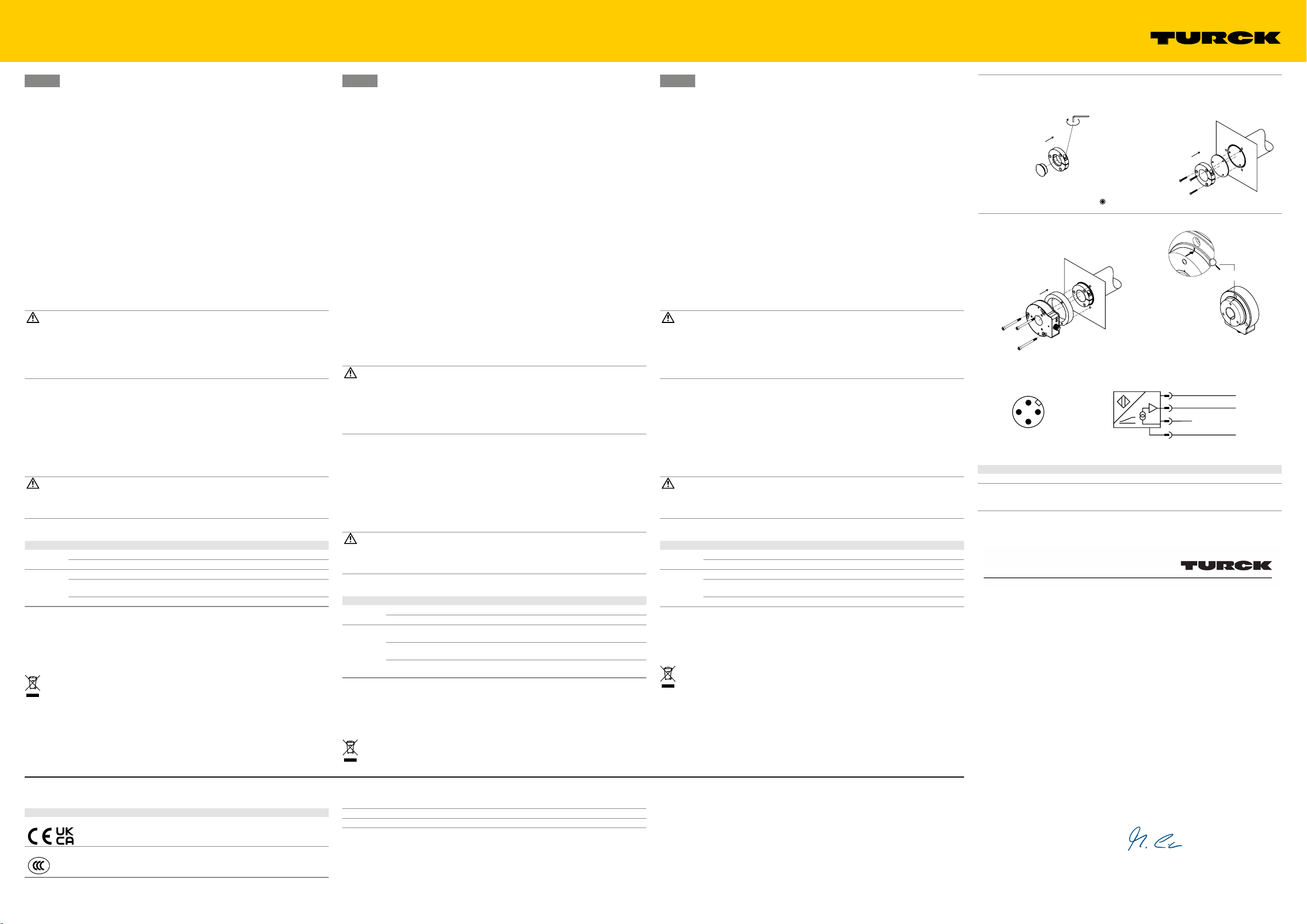
Wiring diagram
4 BK
3 BU 1 BN
2
–
+
1 BN
3 BU
4 BK IO-Link
2 n.c.
Declaration of conformity
EU-Konformitätserklärung Nr.: 5318-1M
EU Declaration of Conformity No.:
Wir/ We:HANS TURCK GMBH & CO KG
WITZLEBENSTR. 7, 45472 MÜLHEIM A.D. RUHR
erklären in alleiniger Verantwortung, dass die Produkte
declare under our sole responsibility that the products
Berührungsloser Drehgeber:
Contactless Encoder:
RI360P0-QR24M0-****-****/3GD
auf die sich die Erklärung bezieht, den Anforderungen der folgenden EU-Richtlinien durch Einhaltung der
folgenden Normen genügen:
to which this declaration relates are in conformity with the requirements of the following EU-directives by compliance with the following
standards:
EMV - Richtlinie /EMC Directive 2014 / 30 / EU 26.02.2014
EN 61326-2-3:2013
ATEX - Richtlinie /Equipment and Protective Systems
Intended for Use in Potentially Explosive Atmospheres
2014 / 34 / EU 26.02.2014
EN IEC 60079-0:2018 EN IEC 60079-7:2015+A1:2018 EN 60079-31:2014
RoHS – Richtlinie /RoHS Directive 2011 / 65 / EU 08.06.2011
EN IEC 63000:2018
Weitere Normen, Bemerkungen:
additional standards, remarks:
Zusätzliche Informationen:
Supplementary infomation:
Angewandtes ATEX-Konformitätsbewertungsverfahren:
ATEX - conformity assessment procedure applied:
Modul A /module A
Baumusterprüfbescheinigung: TURCK Ex-18004HX
examination certificate:
ausgestellt: Hersteller/ Manufacturer:
issued by: Hans Turck GmbH & Co. KG
Mülheim a. d. Ruhr, den 03.11.2022
i.V. Dr. M. Linde, Bereichsleiter Zulassungen /Head of Approvals
Ort und Datum der Ausstellung / Name, Funktion und Unterschrift des Befugten /
Place and date of issue Name, function and signature of authorized person
IO-Link Process Data
Bit 16…31 (MSB) Bit 3…15 Bit 2 Bit 1 Bit 0 (LSB)
Singleturn
position
16 bit
Multiturn counter
13 bit
Multiturn
warning
1 bit
Signal lost
1 bit
Signal weak
1 bit
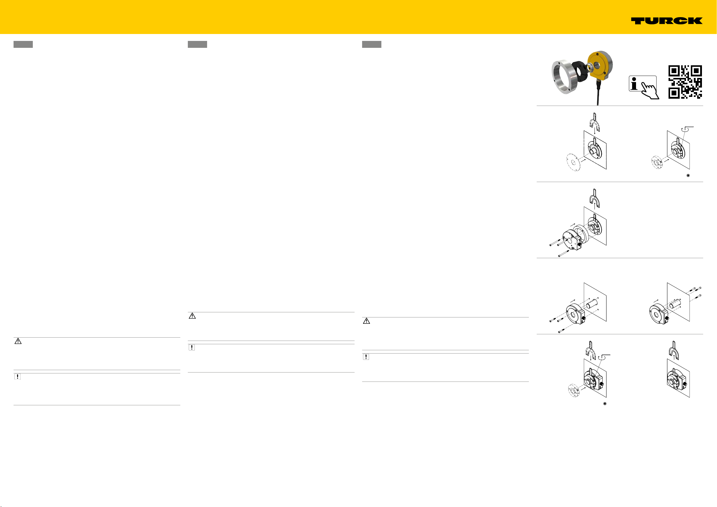
Rückseitig montieren – Wellendurchmesser bis 20mm (Abb. 5, Abb. 6, Abb. 7 und Abb. 8)
Drehgeber mit der Rückseite zur Welle auf die Welle schieben und mit drei Schrauben auf
einer Befestigungsplatte mit Gewindebohrung befestigen (Abb. 5 – Position 1).
Drehgeber mit der Rückseite zur Welle auf die Welle schieben und mit drei Schrauben im
Drehgeber befestigen (Abb. 6 – Position 1).
Montagehilfe zur optimalen Ausrichtung des Positionsgebers ansetzen (Position 2).
Positionsgeber auf die Welle schieben und auf die gewünschte Position des Nullpunkts
ausrichten (Position 3). (Werkseinstellung für 0°: gelber Pfeil am Positionsgeber zeigt auf
schwarze Markierung am Sensor, siehe Abb. 12).
Klemmverschraubung des Positionsgebers mit Innensechskantschlüssel befestigen (Position4).
Montagehilfe entfernen (Position 5).
Schutzring und optional Abschirmplatte SP1-QR24 einsetzen.
Auf größeres drehbares Maschinenteil montieren (Abb. 9, Abb. 10 und Abb. 11)
Falls noch nicht vorhanden: Blindstopfen RA8-QR24 in Positionsgeber einstecken (Position1).
Klemmverschraubung des Positionsgebers mit Innensechskantschlüssel befestigen (Position2).
Abschirmplatte SP3-QR24 einsetzen (Position 3).
Positionsgeber über drei M3-Senkkopfschrauben aus Edelstahl befestigen (Position 4).
Drehgeber inkl. Schutzring je nach Applikation montieren und auf die gewünschte Position
des Nullpunkts ausrichten (Werkseinstellung für 0°: gelber Pfeil am Positionsgeber zeigt auf
schwarze Markierung am Sensor, siehe Abb. 12).
Anschließen
GEFAHR
Explosionsfähige Atmosphäre
Explosion durch zündfähige Funken
Bei Einsatz in Zone 2 und Zone 22:
Gerät nur anschließen, wenn keine explosionsfähige Atmosphäre vorliegt, oder im
spannungslosen Zustand.
Steckverbinder am Gerät mit einem zusätzlichen Sicherheits-Clip versehen.
Drehgeber gemäß„Wiring diagram“ anschließen.
Steckverbinder am Gerät mit einem zusätzlichen Sicherheits-Clip versehen.
In der Nähe des Steckverbinders einen Warnhinweis mit folgender Aufschrift anbringen:
„NICHT UNTER SPANNUNG TRENNEN/DO NOT SEPARATE WHEN ENERGIZED“.
In Betrieb nehmen
Nach Aufschalten der Versorgungsspannung geht das Gerät automatisch in Betrieb.
Betreiben
WARNUNG
Überschreitung der max. Drehzahl
Mögliche Lebensgefahr durch herumschleudernde Bauteile
Maximale Drehzahl von 800 U/min nicht überschreiten.
LED-Anzeigen
LED Anzeige Bedeutung
grün an Versorgung einwandfrei
blinkt Versorgung einwandfrei, IO-Link-Kommunikation
gelb aus Positionsgeber im Messbereich
an Positionsgeber im Messbereich, Signalqualität vermin-
dert (z. B. zu großer Abstand)
blinkt Positionsgeber nicht im Messbereich
Reparieren
Das Gerät ist nicht zur Reparatur durch den Benutzer vorgesehen. Sollte das Gerät defekt sein,
nehmen Sie es außer Betrieb. Bei Rücksendung an Turck beachten Sie bitte unsere Rücknahme-
bedingungen.
Entsorgen
Die Geräte müssen fachgerecht entsorgt werden und gehören nicht in den normalen
Hausmüll.
DE Kurzbetriebsanleitung EN Quick Start Guide
Rear mounting – shaft diameter up to 20mm (g. 5, g. 6, g. 7 and g. 8)
Push the encoder with the rear to the shaft onto the shaft and fasten with the three screws
onto a fixing plate with a threaded hole (fig. 5 – 1).
Push the encoder – with the rear to the shaft – onto the shaft and fasten with three screws in
the encoder (fig. 6 – 1).
Mounting aid for optimum alignment of the positioning element (2).
Push the positioning element onto the shaft and align to the required position of the zero
point (3). (factory setting for 0°: yellow arrow on the positioning element pointing to the
black marking on the sensor, see fig. 12).
Fasten the clamp fitting of the positioning element with hexagon spanner (4).
Remove the mounting aid (5).
Use protecting ring and optional SP1-QR24 shield plate.
Mounting on a larger rotating machine part (g. 9, g. 10 and g. 11)
If not yet present: insert blanking plug RA8-QR24 (1).
Fasten the clamp fitting of the positioning element with hexagon spanner (2).
Use the SP3-QR24 shield plate (3).
Fasten the positioning element with three stainless steel M3 countersunk screws (4).
Depending on the application, install the encoder, including the protecting ring, and align
to the required position of the zero point (factory setting for 0°: yellow arrow on the posi-
tioning element pointing to the black marking on the sensor, see fig. 12).
Connection
DANGER
Potentially explosive atmosphere
Risk of explosion due to spark ignition
Use of devices in Zone 2 and Zone 22:
Only connect the device if there is no potentially explosive atmosphere present, or in a
de-energized state.
Secure the connector to the device using an additional safety clip.
Connect the encoder as shown in“Wiring diagram”.
Provide the connector on the device with an additional safety clip.
Affix a label close to the connector with the following warning: “NICHT UNTER SPANNUNG
TRENNEN/DO NOT SEPARATE WHEN ENERGIZED”.
Commissioning
The device is operational automatically once the power supply is switched on.
Operation
WARNING
Exceeding maximum speed
Possible fatal injury from fast moving parts
Do not exceed the maximum speed of 800 rpm.
LEDs
LED Indication Meaning
Green On Power supply correct
Flashing Power supply correct, IO-Link communication
Yellow Off Positioning element in the measuring range
On Positioning element in the measuring range, reduced
signal quality (e.g. distance too large)
Flashing Positioning element not in the measuring range
Repair
The device is not intended for repair by the user. The device must be decommissioned if it is
faulty. Observe our return acceptance conditions when returning the device to Turck.
Disposal
The devices must be disposed of properly and do not belong in the domestic waste.
FR Guide d’utilisation rapide
Placez l’encodeur avec la bague de protection, l’avant faisant face à l’arbre sur le transmet-
teur de position, et alignez-le sur la position requise du point zéro (6) (réglage en sortie
d’usine pour 0°: flèche jaune sur le transmetteur de position pointant vers le repère noir sur
le capteur, voir fig.12).
Fixez l’encodeur avec trois vis afin d’obtenir une unité fermée et protégée.
Montage arrière – diamètre d’arbre jusqu’à 20mm (g.5, g.6, g.7 et g.8)
Placez l’encodeur sur l’arbre, l’arrière positionné vers l’arbre, et fixez-le avec les trois vis sur
une plaque de fixation avec un trou de filetage (fig.5 – 1).
Placez l’encodeur sur l’arbre, l’arrière positionné vers l’arbre, et fixez-le à l’aide de trois vis
dans l’encodeur (fig. 6 – 1).
Dispositif de montage pour l’alignement optimal du transmetteur de position (2).
Placez le transmetteur de position sur l’arbre et alignez-le sur la position requise du point
zéro (3) (réglage en sortie d’usine pour 0°: flèche jaune sur le transmetteur de position
pointant vers le repère noir sur le capteur, voir fig.12).
Fixez le raccord de serrage du transmetteur de position à l’aide d’une clé hexagonale (4).
Retirez l’accessoire de montage (5).
Utilisez une bague de protection et une plaque de protection SP1-QR24 en option.
Montage sur une plus grande partie rotative de la machine (g.9, g.10 et g.11)
S’il n’est pas encore installé: insérez le bouchon d’obturation RA8-QR24 (1).
Fixez le raccord de serrage du transmetteur de position à l’aide d’une clé hexagonale (2).
Utilisez la plaque de protection SP3-QR24 (3).
Fixez le transmetteur de position avec trois vis à tête fraisée en acier inoxydable M3 (4).
Selon l’application, installez l’encodeur, y compris la bague de protection, et alignez-le sur la
position requise du point zéro (réglage en sortie d’usine pour 0°: flèche jaune sur le trans-
metteur de position pointant vers le repère noir sur le capteur, voir fig.12).
Raccordement
DANGER
Atmosphère présentant un risque d'explosion
Explosion par étincelles inammables
Utilisation des appareils en zone2 et en zone22:
Effectuez le raccordement de l'appareil uniquement hors de toute atmosphère explosive
ou hors de toute tension.
Munissez le connecteur de l'appareil d'une broche de sécurité supplémentaire.
Raccordez l’encodeur conformément au schéma électrique («Wiring diagram»).
Munissez le connecteur de l’appareil d’une broche de sécurité supplémentaire.
Collez une étiquette à proximité du connecteur avec l’avertissement suivant: «DO NOT
SEPARATE WHEN ENERGIZED/DÉFENSE DE DÉCONNECTER SOUS TENSION».
Mise en service
L’appareil se met automatiquement en marche après activation de la tension d’alimentation.
Fonctionnement
AVERTISSEMENT
Dépassement de la vitesse maximale
Risques de blessures mortelles causées par des pièces en mouvement rapide
Ne dépassez pas la vitesse maximale de 800tr/min.
LED
LED Indication Signication
Vert Activée Alimentation correcte
Clignote Alimentation correcte, communication IO-Link
Jaune Désactivée Le transmetteur de position est dans la plage de
mesure
Activée Transmetteur de position dans la plage de mesure,
qualité du signal réduite (p.ex. distance trop élevée)
Clignote Le transmetteur de position n'est pas dans la plage de
mesure
Réparation
L’appareil ne peut pas être réparé par l’utilisateur. En cas de dysfonctionnement, mettez l’appa-
reil hors service. En cas de retour à Turck, veuillez respecter les conditions de reprise.
Mise au rebut
Les appareils doivent être mis au rebut de manière appropriée et ne doivent pas être
placés dans les ordures ménagères.