turck REM Series User manual

Your Global Automation Partner
Instructions for Use
REM…|RES…
Encoders with
IO-Link Interface

Contents
Hans Turck GmbH & Co. KG | T +49 208 4952-0 | [email protected] | www.turck.com V03.00 | 2022/12 | 2
Contents
1 About these instructions ...................................................................................................................3
1.1 Target groups ...................................................................................................................3
1.2 Explanation of symbols used.........................................................................................3
1.3 Other documents.............................................................................................................3
1.4 Feedback about these instructions ..............................................................................3
2 Notes on the product .........................................................................................................................4
2.1 Product identification .....................................................................................................4
2.2 Scope of delivery..............................................................................................................4
2.3 Turck service .....................................................................................................................4
3 For your safety.....................................................................................................................................5
3.1 Intended use .....................................................................................................................5
3.2 Obvious misuse ................................................................................................................5
3.3 General safety notes........................................................................................................5
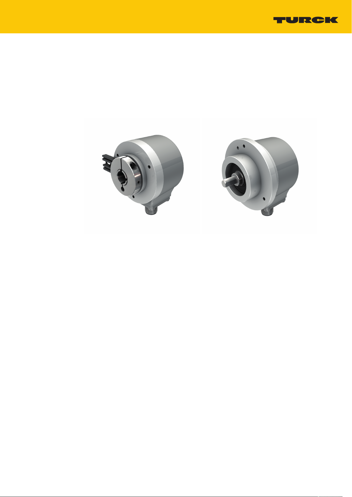
4 Product description ............................................................................................................................6
4.1 Device overview...............................................................................................................6
4.1.1 Display elements ..............................................................................................................................6
4.2 Operating principle .........................................................................................................6
4.3 Functions and operating modes...................................................................................6
4.3.1 IO-Link mode......................................................................................................................................7
4.4 Technical accessories ......................................................................................................7
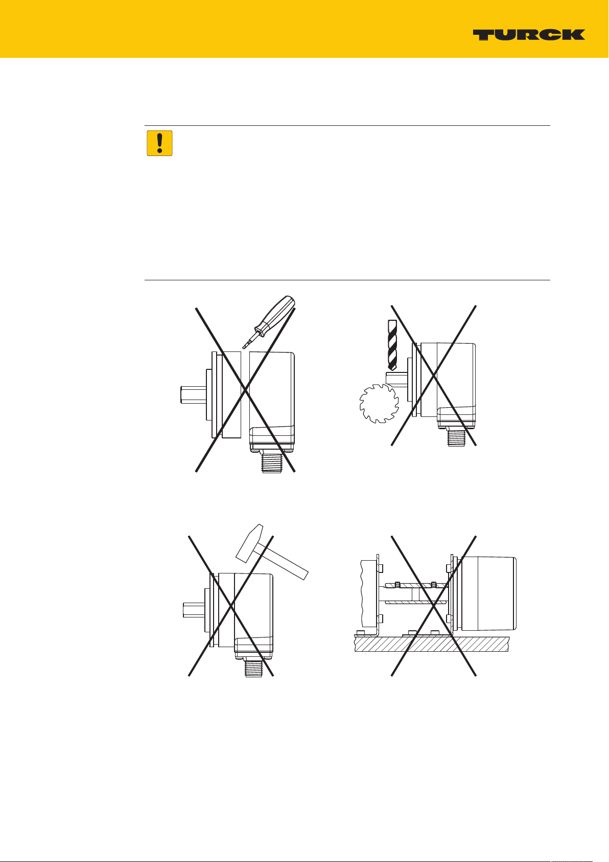
5 Installing ...............................................................................................................................................8
5.1 Mounting the solid shaft encoder using a coupling .................................................9
5.2 Mounting the hollow shaft encoder using a coupling .......................................... 10
6 Connection ........................................................................................................................................ 11
6.1 Wiring diagram.............................................................................................................. 11
7 Commissioning................................................................................................................................. 12
8 Operation........................................................................................................................................... 13
8.1 LED display..................................................................................................................... 13
9 Setting................................................................................................................................................ 14
9.1 Setting via IO-Link ........................................................................................................ 14
9.1.1 IO-Link parameters ....................................................................................................................... 14
9.2 Setting via FDT/IODD ................................................................................................... 17
10 Troubleshooting............................................................................................................................... 18
11 Maintenance ..................................................................................................................................... 19
12 Repair ................................................................................................................................................. 19
12.1 Returning devices ......................................................................................................... 19
13 Disposal.............................................................................................................................................. 19
14 Turck subsidiaries — contact information.................................................................................. 20

About these instructions
Feedback about these instructions
Hans Turck GmbH & Co. KG | T +49 208 4952-0 | [email protected] | www.turck.com V03.00 | 2022/12 | 3
1 About these instructions
These instructions for use describe the structure, functions and the use of the product and will
help you to operate the product as intended. Read these instructions carefully before using the
product. This is to avoid possible damage to persons, property or the device. Retain the instruc-
tions for future use during the service life of the product. If the product is passed on, pass on
these instructions as well.
1.1 Target groups
These instructions are aimed at qualified personal and must be carefully read by anyone
mounting, commissioning, operating, maintaining, dismantling or disposing of the device.
1.2 Explanation of symbols used
The following symbols are used in these instructions:
DANGER
DANGER indicates a dangerous situation with high risk of death or severe injury if
not avoided.
WARNING
WARNING indicates a dangerous situation with medium risk of death or severe
injury if not avoided.
CAUTION
CAUTION indicates a dangerous situation of medium risk which may result in minor
or moderate injury if not avoided.
NOTICE
NOTICE indicates a situation which may lead to property damage if not avoided.
NOTE
NOTE indicates tips, recommendations and useful information on specific actions
and facts. The notes simplify your work and help you to avoid additional work.
uCALL TO ACTION
This symbol denotes actions that the user must carry out.
aRESULTS OF ACTION
This symbol denotes relevant results of actions.
1.3 Other documents
Besides this document, the following material can be found on the Internet at www.turck.com:
nData sheet
nQuick Start Guide
nIO-Link parameters manual
nCommissioning manual IO-Link devices
1.4 Feedback about these instructions
We make every effort to ensure that these instructions are as informative and as clear as
possible. If you have any suggestions for improving the design or if some information is missing
in the document, please send your suggestions to [email protected].

Notes on the product
Turck service
Hans Turck GmbH & Co. KG | T +49 208 4952-0 | [email protected] | www.turck.com V03.00 | 2022/12 | 4
2 Notes on the product
2.1 Product identification
These instructions apply to the following encoders with an IO-Link interface:
nREM-…IOL…-H1141
nRES-…IOL…-H1141
2.2 Scope of delivery
The scope of delivery includes:
nEncoder – sensor
nQuick Start Guide
2.3 Turck service
Turck supports you with your projects, from initial analysis to the commissioning of your applic-
ation. The Turck product database under www.turck.com contains software tools for program-
ming, configuration or commissioning, data sheets and CAD files in numerous export formats.
The contact details of Turck subsidiaries worldwide can be found on p. [}20].

For your safety
General safety notes
Hans Turck GmbH & Co. KG | T +49 208 4952-0 | [email protected] | www.turck.com V03.00 | 2022/12 | 5
3 For your safety
The product is designed according to state-of-the-art technology. However, residual risks still
exist. Observe the following warnings and safety notices to prevent damage to persons and
property. Turck accepts no liability for damage caused by failure to observe these warning and
safety notices.
3.1 Intended use
The rotary encoders with an IO-Link interface are used for measuring speeds and angle move-
ments. To do this the devices detect mechanical rotary movements and convert them into a
digital IO-Link telegram. The devices can be operated and parameterized via an IO-Link inter-
face with IO-Link masters compliant with specification 1.1. Process and diagnostics data can be
exchanged with the higher controller level during operation via IO-Link.
The devices may only be used as described in these instructions. Any other use is not in accord-
ance with the intended use. Turck accepts no liability for any resulting damage.
3.2 Obvious misuse
nThe devices are not safety components and must not be used for personal or property
protection.
nAny use that exceeds the maximum permissible mechanical speed (see technical data) is
deemed to be not in accordance with the intended purpose.
3.3 General safety notes
nThe device meets the EMC requirements for industrial areas. When used in residential areas,
take measures to avoid radio interference.
nThe device may only be assembled, installed, operated, parameterized and maintained by
professionally-trained personnel.
nThe device may only be used in accordance with applicable national and international
regulations, standards and laws.
nIf safe operation is no longer guaranteed: Take the device out of operation and ensure that it
cannot be switched on again accidentally.

Product description
Functions and operating modes
Hans Turck GmbH & Co. KG | T +49 208 4952-0 | [email protected] | www.turck.com V03.00 | 2022/12 | 6
4 Product description
The encoders with an IO-Link interface are available as solid shaft or hollow shaft versions.
Available are devices in three sizes from 36 to 58 mm.
The encoders can be connected via a standard 4-pin connector. The devices can be operated
and set via IO-Link.
4.1 Device overview
Fig.1: Example — encoder with hollow shaft Fig.2: Example — encoder with solid shaft
4.1.1 Display elements
The device has two LED displays.
4.2 Operating principle
Encoders detect rotational movements, such as the angle velocity of a shaft. Encoders convert
the rotational movements into electrical signals. The devices pass on the electrical signals to a
higher-level controller for evaluation. Encoders are designed as absolute and incremental
encoders with hollow or solid shafts.
Absolute encoders also supply the angle value after a startup if the value has changed when
deactivated. Incremental encoders only detect position changes when active by counting
periodic patterns. This normally involves the optical scanning of a rotating disk.
4.3 Functions and operating modes
The devices can be operated in IO-Link mode. The devices must be connected to an IO-Link
master for operation in IO-Link mode. Different device functions can be configured via the
IO-Link interface.

Product description
Technical accessories
Hans Turck GmbH & Co. KG | T +49 208 4952-0 | [email protected] | www.turck.com V03.00 | 2022/12 | 7
4.3.1 IO-Link mode
IO-Link mode provides bidirectional IO-Link communication between an IO-Link master and
the sensors. For this the devices are integrated in the controller level via an IO-Link master. The
switching signals are processed via the process data of the IO-Link interface. Besides the switch-
ing information, diagnostics and identification messages can be queried via IO-Link. The follow-
ing device parameters can be adapted to the particular application via IO-Link:
nDevice access protection
nRotation direction
nZero setting
nMultiturn reset
nReset settings
4.4 Technical accessories
Dimension drawing Type Description
41
24
54
M12 × 1 16
USB-Mini
IN-DC
LED:
CH1 (C/Q)
CH2 (DI/DO)
Error
LED: PWR
USB-2-IOL-0002 IO-Link adapter with integrated USB
interface
42
11.5
ø 15
M12 x 1
L
M12 x 1ø 15
49.5
18.2
RKC4.4T-2-RSC4.4T/TXL Connection cable, M12 female
connector, straight 4-pin, M12 male
connector, straight 4-pin, cable length:
2 m, jacket material: PUR, black; cULus
approval; other cable lengths and types
available, see www.turck.com
42
11.5
ø 15
M12 x 1
L
50
5
RKC4.4T-2/TXL Connection cable, M12 female
connector, straight, 4-pin, cable length:
2 m, jacket material: PVC, black; cULus
approval; other cable lengths and types
available, see www.turck.com

Installing
Hans Turck GmbH & Co. KG | T +49 208 4952-0 | [email protected] | www.turck.com V03.00 | 2022/12 | 8
5 Installing
NOTICE
Incorrect mounting
Risk of damage to the sensor
Do not modify or disassemble the encoder.
Do not make adjustments to the shaft after mounting.
Do not use a hammer to align the device.
Avoid impact loads.
Load the encoder shaft only within the permissible values (see technical data).
Do not rigidly connect the rotary encoder to shafts and flanges at the same time.
Use the coupling between the drive shaft and the encoder shaft or the hollow
shaft encoder flange.
Fig.3: Mounting view — do not open Fig.4: Mounting view — do not make
adjustments after mounting
Fig.5: Mounting view — do not
use a hammer to align the device
Fig.6: Mounting view — do not rigidly connect
the device to shafts and flanges at the same
time

Installing
Mounting the solid shaft encoder using a coupling
Hans Turck GmbH & Co. KG | T +49 208 4952-0 | [email protected] | www.turck.com V03.00 | 2022/12 | 9
5.1 Mounting the solid shaft encoder using a coupling
Check shaft for displacement.
Refer to the technical data for the coupling for the maximum axial displacement, radial
displacement, and angular displacement values.
D
M
Fig.7: Axial displacement Fig.8: Radial displacement
α
Fig.9: Angular displacement
During mounting, protect the coupling against excessive bending and damage.
Align the coupling on the shaft.
Secure the coupling on the device using tensioning screws or clamping screws. For the
maximum tightening torque, refer to the data sheet of the screws used.

Installing
Mounting the hollow shaft encoder using a coupling
Hans Turck GmbH & Co. KG | T +49 208 4952-0 | [email protected] | www.turck.com V03.00 | 2022/12 | 10
5.2 Mounting the hollow shaft encoder using a coupling
Mount the encoder with the coupling on the shaft.
Fig.10: Mounting on the shaft with the coupling
Screw the coupling to the drive flange.
Fig.11: Screwing the coupling to the drive flange
Carefully tighten the clamping hub.
Fig.12: Tightening the clamping hub

Connection
Wiring diagram
Hans Turck GmbH & Co. KG | T +49 208 4952-0 | [email protected] | www.turck.com V03.00 | 2022/12 | 11
6 Connection
The encoder is provided with a 4-pin M12 ×1 male connector with an IO-Link interface. Refer to
the sensor label or data sheet for the pin layout.
Turck recommends the following cable lengths:
nFor asymmetrical transmission (no inverted signals): max. 10m
nFor symmetrical transmission (e.g. RS422 standard): max. 50m with twisted pairs
Connect all required cable cores as per the wiring diagram. Insulate the cable ends that
are not required to avoid short circuits.
Follow the operating instructions for the connecting cable used.
Disconnect the encoder from the connecting cable only when the encoder is de-ener-
gized.
Connect the shielding (if present) to the encoder housing.
The encoder and processor must always be switched on and off simultaneously.
Observe the operating voltage and maximum permissible output current (see technical
data).
EMC-compliant installation
Use shielded connection cables as control cables.
For symmetrical transmission (e.g. via RS422): Use twisted pair cables.
Connect protective earth to the rotary encoder and the evaluation unit (low impedance).
Route the connection cables separately from cables with high noise levels.
Do not connect devices with high noise levels to the encoder's power supply (e.g.
frequency converters, solenoid valves, or contactors), or ensure that suitable voltage
filtering is in place.
6.1 Wiring diagram
1
4
2
3
+
–
IO-Link
n. c.
Fig.13: REM…|RES…-IO-Link – wiring diagram

Commissioning
Hans Turck GmbH & Co. KG | T +49 208 4952-0 | [email protected] | www.turck.com V03.00 | 2022/12 | 12
7 Commissioning
After connecting and switching on the power supply, the device is automatically ready for
operation.

Operation
LED display
Hans Turck GmbH & Co. KG | T +49 208 4952-0 | [email protected] | www.turck.com V03.00 | 2022/12 | 13
8 Operation
The encoder supplies at the output the IO-Link process data corresponding proportionally to
the position of the positioning element. The IO-Link process data contains the following
information:
nCurrent angle information (single-turn data)
nNumber of revolutions of the positioning element:
The multiturn process data is calculated internally from the number of single-turn zero
crossings.
8.1 LED display
In normal operation the LEDs have the following indication functions:
Color/state Meaning
Green Device is in idle state and waiting for IO-Link WakeUp request.
Green flashing IO-Link communication is active.
Flashing 3 ×
green
A firmware download is executed.
Red Device is faulty
Red flashing An IO-Link error has occurred.
Flashing 1 × red IO-Link warning is displayed.

Setting
Setting via IO-Link
Hans Turck GmbH & Co. KG | T +49 208 4952-0 | [email protected] | www.turck.com V03.00 | 2022/12 | 14
9 Setting
The encoder can be set via the IO-Link interface.
9.1 Setting via IO-Link
The devices can be parameterized via the IO-Link communication interface within the limits of
their technical specifications. For further information on IO-Link see the IO-Link commissioning
manual (D900634).
9.1.1 IO-Link parameters
Different parameters can be set for the particular application via the IO-Link interface. Further
information on the IO-Link parameters can be obtained from the IO-Link parameter manual or
the IODDfinder.
The default values are shown in bold type.
Parameter Parameter value
Block device access
(switch off parameter server function)
On
Off
Rotation direction Clockwise
Counter clockwise
Set zero point and reset multiturn
Multiturn reset
Reset to factory setting
Application-specific marking

Setting
Setting via IO-Link
Hans Turck GmbH & Co. KG | T +49 208 4952-0 | [email protected] | www.turck.com V03.00 | 2022/12 | 15
Different multiturn and scaling parameters can also be set in the device via the IO-Link
interface.
Parameter Meaning
Lower limit position An alarm can be set for the lower limit of the
total measuring range (TMR) Default: 0
Upper limit position An alarm can be set for the upper limit of the
total measuring range (TMR). Default:
4294967295
Limit control position The alarm messages for the lower and upper
limit of the total measuring range (TMR) can be
activated or deactivated. Default: Activated
Preset value A start value for the total measuring range can
be set via this parameter. The start value must
be less than the total measuring range, other-
wise the Preset value is set to 0. Default: 0
Measuring units per revolution (MUR) The maximum resolution per revolution can be
set via this parameter. The resolution must be
between 1…16384 (214). Default: 16384
Total measuring range (TMR) The upper limit for the total measuring range
can be set via this parameter. The TMR must be
greater than the MUR. Calculation formula:
MUR × 2n (number of revolutions)
The adjustable upper limit value for the total
measuring range is 4…4294967296 (232).
Default: 4294967296
The maximum number of revolutions must not
exceed 262144 (218).
Scaling control The parameter must be activated in order to
use the MUR parameter. The number of revolu-
tions must be set via the scaling of 2n and can-
not therefore assume any value. The Endless
shaft control parameter must be deactivated.
Default: Activated
Endless shaft control The Scaling control parameter must be deac-
tivated The number of revolutions can be
defined precisely via the Numerator and
Denominator parameters.
Default: Deactivated
Calculation example for the maximum possible TMR (Scaling control)
Formula for calculating the maximum possible TMR:
MUR × 2m (number of revolutions) ≤ 4294967296 (232)
Example: The MUR value is 3600 for a 0.1° revolution of the encoder.
The maximum possible TMR is calculated as follows:
n3600 × 2m ≤ 4294967296 (232)
nMaximum possible TMR: 3600 × 218 = 943718400

Setting
Setting via IO-Link
Hans Turck GmbH & Co. KG | T +49 208 4952-0 | [email protected] | www.turck.com V03.00 | 2022/12 | 16
Calculation example for the TMR (Scaling control)
Formula for calculating the TMR:
MUR × 2m (number of revolutions) ≤ 4294967296 (232)
Example: The MUR value is 360 for a 1° revolution of the encoder. The TMR parameter is reset to
0 after 1000 revolutions. If the Scaling control parameter is activated, the number of revolu-
tions can be defined approximately.
The TMR is calculated as follows:
n360 × 2m ≤ 4294967296 (232)
n512 (29) < 1000 < 1024 (210)
nChoose the higher factor for further calculation (here: 10).
nTMR with 1024 revolutions: 360 × 210 = 368640
Calculation example for the TMR (Endless shaft control)
Formula for calculating the TMR:
MUR × (numerator/denominator) ≤ 4294967296 (232)
Example: The MUR value is 360 for a 1° revolution of the encoder. The TMR parameter is reset to
0 after 1000 revolutions. If the Endless shaft control paramter is activated, the number of
revolutions can be defined precisely.
The TMR is calculated as follows:
n360 × (1000/1) = 360000

Setting
Setting via FDT/IODD
Hans Turck GmbH & Co. KG | T +49 208 4952-0 | [email protected] | www.turck.com V03.00 | 2022/12 | 17
9.2 Setting via FDT/IODD
The devices can be set via a PC with an FDT frame application (e.g. PACTware). All the required
Turck software components can be downloaded via the Turck Software Manager:
nPACTware
nIODD
nDTM for USB-2-IOL-002 IO-Link adapter
nIODD DTM Configurator
The Turck Software Manager can be downloaded free of charge from www.turck.com.
The USB-2-IOL-002 USB IO-Link adapter (ID 6825482) is required for connecting to the PC.
A 4-pin standard sensor cable (e.g. RKC4.4T-2- RSC4.4T/TXL, ID 6625608) is required for
connecting the sensor to the USB-2-IOL-002 IO-Link adapter.
Further information on setting the devices via IODD with a configuration tool is provided in the
IO-Link commissioning manual.

Troubleshooting
Hans Turck GmbH & Co. KG | T +49 208 4952-0 | [email protected] | www.turck.com V03.00 | 2022/12 | 18
10 Troubleshooting
If the device does not function as expected, first check whether ambient interference is present.
If there is no ambient interference present, check the connections of the device for faults.
If there are no faults, there is a device malfunction. In this case, decommission the device and
replace it with a new device of the same type.

Maintenance
Returning devices
Hans Turck GmbH & Co. KG | T +49 208 4952-0 | [email protected] | www.turck.com V03.00 | 2022/12 | 19
11 Maintenance
Ensure that the plug connections and cables are always in good condition.
The devices are maintenance-free, clean dry if required.
12 Repair
The device must not be repaired by the user. The device must be decommissioned if it is faulty.
Observe our return acceptance conditions when returning the device to Turck.
12.1 Returning devices
Returns to Turck can only be accepted if the device has been equipped with a Decontamination
declaration enclosed. The decontamination declaration can be downloaded from
https://www.turck.de/en/retoure-service-6079.php
and must be completely filled in, and affixed securely and weather-proof to the outside of the
packaging.
13 Disposal
The devices must be disposed of correctly and must not be included in general
household garbage.

Turck subsidiaries — contact information
Hans Turck GmbH & Co. KG | T +49 208 4952-0 | [email protected] | www.turck.com V03.00 | 2022/12 | 20
14 Turck subsidiaries — contact information
Germany Hans Turck GmbH & Co. KG
Witzlebenstraße 7, 45472 Mülheim an der Ruhr
www.turck.de
Australia Turck Australia Pty Ltd
Building 4, 19-25 Duerdin Street, Notting Hill, 3168 Victoria
www.turck.com.au
Austria Turck GmbH
Graumanngasse 7/A5-1, A-1150 Wien
www.turck.at
Belgium TURCK MULTIPROX
Lion d'Orweg 12, B-9300 Aalst
www.multiprox.be
Brazil Turck do Brasil Automação Ltda.
Rua Anjo Custódio Nr. 42, Jardim Anália Franco, CEP 03358-040 São Paulo
www.turck.com.br
Canada Turck Canada Inc.
140 Duffield Drive, CDN-Markham, Ontario L6G 1B5
www.turck.ca
China Turck (Tianjin) Sensor Co. Ltd.
18,4th Xinghuazhi Road, Xiqing Economic Development Area, 300381
Tianjin
www.turck.com.cn
Czech Republic TURCK s.r.o.
Na Brne 2065, CZ-500 06 Hradec Králové
www.turck.cz
France TURCK BANNER S.A.S.
11 rue de Courtalin Bat C, Magny Le Hongre, F-77703 MARNE LA VALLEE
Cedex 4
www.turckbanner.fr
Great Britain TURCK BANNER LIMITED
Blenheim House, Hurricane Way, GB-SS11 8YT Wickford, Essex
www.turckbanner.co.uk
Hungary TURCK Hungary kft.
Árpád fejedelem útja 26-28., Óbuda Gate, 2. em., H-1023 Budapest
www.turck.hu
India TURCK India Automation Pvt. Ltd.
401-403 Aurum Avenue, Survey. No 109 /4, Near Cummins Complex,
Baner-Balewadi Link Rd., 411045 Pune - Maharashtra
www.turck.co.in
Italy TURCK BANNER S.R.L.
Via San Domenico 5, IT-20008 Bareggio (MI)
www.turckbanner.it
Other manuals for REM Series
2
This manual suits for next models
2
Table of contents
Other turck Media Converter manuals

turck
turck QR24 User manual

turck
turck QR24 User manual

turck
turck REM Series User manual

turck
turck RI360P0-QR24M0-IOLX2-H1141/3GD User manual

turck
turck RI QR20 Series User manual

turck
turck RI360P0-EQR24M0-HESG25X3-H1181 User manual

turck
turck RES Series User manual

turck
turck FOC1 Series User manual

turck
turck PE1-QR24 Operation manual

turck
turck Ri-QR24 User manual