turck REM Series User manual

Your Global Automation Partner
Instructions for Use
REM…|RES…
Encoders with CANopen
Interface

Contents
Hans Turck GmbH & Co. KG | T +49 208 4952-0 | [email protected] | www.turck.com V02.00 | 2022/10 | 2
Contents
1 About these instructions ...................................................................................................................4
1.1 Target groups ...................................................................................................................4
1.2 Explanation of symbols used.........................................................................................4
1.3 Other documents.............................................................................................................4
1.4 Feedback about these instructions ..............................................................................4
2 Information About the Product........................................................................................................5
2.1 Product identification .....................................................................................................5
2.2 Scope of delivery..............................................................................................................5
2.3 Turck service .....................................................................................................................5
3 For Your Safety ....................................................................................................................................6
3.1 Intended use .....................................................................................................................6
3.2 Obvious misuse ................................................................................................................6
3.3 General safety notes........................................................................................................6
4 Product Description............................................................................................................................7
4.1 Device overview...............................................................................................................7
4.1.1 Display elements ..............................................................................................................................7
4.2 Operating principle .........................................................................................................7
4.3 Functions and operating modes...................................................................................7
4.3.1 Output function................................................................................................................................7
4.3.2 Terminating resistor ........................................................................................................................7
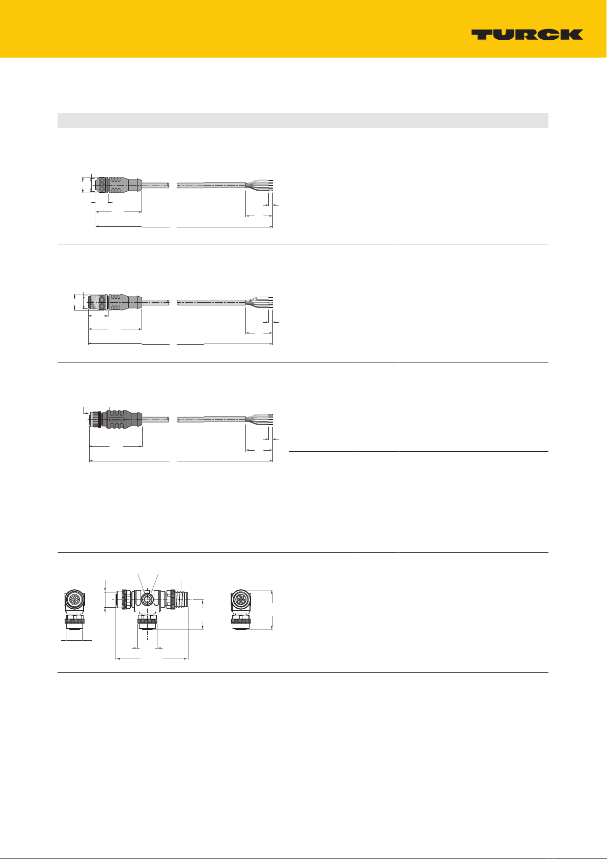
4.4 Technical accessories ......................................................................................................8
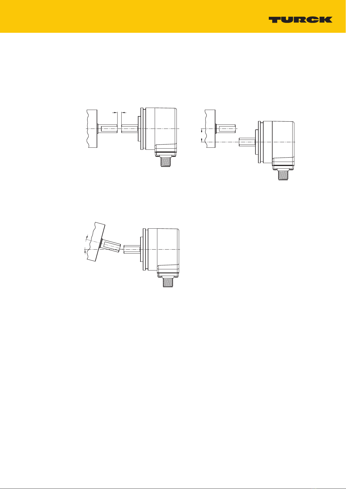
5 Installing ...............................................................................................................................................9
5.1 Mounting the solid shaft encoder using a coupling .............................................. 10
5.2 Mounting the hollow shaft encoder using a coupling .......................................... 11
6 Connection ........................................................................................................................................ 12
6.1 Wiring diagram.............................................................................................................. 12
7 Commissioning................................................................................................................................. 13
8 Operation........................................................................................................................................... 14
8.1 LED display..................................................................................................................... 14
9 Setting................................................................................................................................................ 15
9.1 Communication profiles.............................................................................................. 15
9.1.1 Object 0x1000: Device type....................................................................................................... 15
9.1.2 Object 0x100A: Manufacturer software version................................................................. 15
9.1.3 Object 0x1010: Store parameters............................................................................................ 16
9.1.4 Object 0x1011 Restore default parameters (load default values) ............................... 16
9.1.5 Object 0x1017: Producer heartbeat time (heartbeat cycle)........................................... 17
9.1.6 Object 0x1018: Identity object (device identification) .................................................... 18
9.1.7 Object 0x1029: Error behavior.................................................................................................. 18
9.1.8 Object 0x1800: PDO1 parameters (asynchronous)........................................................... 19
9.1.9 Object 0x1801: PDO2 parameters (synchronous, cyclical)............................................. 20
9.1.10 Transmission types ....................................................................................................................... 21
9.2 Creating variable PDO mapping................................................................................ 22
9.2.1 Changing mapping parameters............................................................................................... 22
9.2.2 Standard settings for the mapping of transmit PDOs...................................................... 23
9.2.3 Object 0x1A00: PDO1 mapped object................................................................................... 23

Contents
Hans Turck GmbH & Co. KG | T +49 208 4952-0 | [email protected] | www.turck.com V02.00 | 2022/10 | 3
9.2.4 Object 0x1A01: PDO2 mapped object................................................................................... 24
9.2.5 Example: Creating PDO mapping for PDO3 (speed) ........................................................ 25
9.2.6 Default setting for the mapping of transmit PDOs........................................................... 26
9.2.7 PDO mapping in accordance with CiA (from CANopen version 4)............................. 26
9.3 Setting parameters specific to the manufacturer................................................... 27
9.3.1 Object 0x2100: Baud rate (setting the transmission rate) .............................................. 27
9.3.2 Object 0x2101: Node number (changing the node address)........................................ 27
9.3.3 Object 0x2102: CANBus termination (switching the terminating resistor on and
off)....................................................................................................................................................... 27
9.3.4 Object 0x2105: Save all bus parameters ............................................................................... 28
9.4 Setting default device parameters............................................................................ 29
9.4.1 Object 0x6000: Operating parameters.................................................................................. 29
9.4.2 Object 0x6001: MUR – Measuring Units per Revolution................................................. 29
9.4.3 Object 0x6002: TMR – Total Measuring Range................................................................... 30
9.4.4 Object 0x6003: Preset value (zero point adjustment)...................................................... 31
9.4.5 Object 0x6004: Current position value.................................................................................. 31
9.4.6 Object 0x600C: Position raw value (unscaled measured value)................................... 31
9.4.7 Object 0x6200: Cycle timer (cycle time of the measured value output)................... 32
9.4.8 Object 0x6400: Work area state register (current status of the limit values)........... 32
9.4.9 Object 0x6401 and 0x6402: Working area limits (adjusting limit values)................. 32
9.4.10 Object 0x6500: Operating status (read only) ...................................................................... 33
9.4.11 Object 0x6501: Single-turn resolution (read only)............................................................ 34
9.4.12 Object 0x6502: Number of distinguishable revolutions (read only)........................... 34
9.4.13 Object 0x6503: Alarms (read only).......................................................................................... 34
9.4.14 Object 0x6504: Supported alarms (read only).................................................................... 34
9.4.15 Object 0x6505: Warnings (read only)..................................................................................... 34
9.4.16 Object 0x6506: Supported warnings (read only)............................................................... 34
9.4.17 Object 0x6507: Profile and software version (read only)................................................ 35
9.4.18 Object 0x6509: Offset value (read only)................................................................................ 35
9.4.19 Object 0x650A: Module identification (manufacturer comparison) (read only).... 35
9.4.20 Object 0x650B: Series number (read only)........................................................................... 35
9.5 LSS services DS 305 V2.0 ............................................................................................. 36
9.6 Network management................................................................................................. 38
10 Troubleshooting............................................................................................................................... 39
11 Maintenance ..................................................................................................................................... 40
12 Repair ................................................................................................................................................. 41
12.1 Returning devices ......................................................................................................... 41
13 Disposal.............................................................................................................................................. 42
14 Turck subsidiaries — contact information.................................................................................. 43

About these instructions
Feedback about these instructions
Hans Turck GmbH & Co. KG | T +49 208 4952-0 | [email protected] | www.turck.com V02.00 | 2022/10 | 4
1 About these instructions
These instructions for use describe the structure, functions and the use of the product and will
help you to operate the product as intended. Read these instructions carefully before using the
product. This is to avoid possible damage to persons, property or the device. Retain the instruc-
tions for future use during the service life of the product. If the product is passed on, pass on
these instructions as well.
1.1 Target groups
These instructions are aimed at qualified personal and must be carefully read by anyone
mounting, commissioning, operating, maintaining, dismantling or disposing of the device.
1.2 Explanation of symbols used
The following symbols are used in these instructions:
DANGER
DANGER indicates a dangerous situation with high risk of death or severe injury if
not avoided.
WARNING
WARNING indicates a dangerous situation with medium risk of death or severe in-
jury if not avoided.
CAUTION
CAUTION indicates a dangerous situation of medium risk which may result in minor
or moderate injury if not avoided.
NOTICE
NOTICE indicates a situation which may lead to property damage if not avoided.
NOTE
NOTE indicates tips, recommendations and useful information on specific actions
and facts. The notes simplify your work and help you to avoid additional work.
uCALL TO ACTION
This symbol denotes actions that the user must carry out.
aRESULTS OF ACTION
This symbol denotes relevant results of actions.
1.3 Other documents
Besides this document, the following material can be found on the Internet at www.turck.com:
nData sheet
nQuick Start Guide
1.4 Feedback about these instructions
We make every effort to ensure that these instructions are as informative and as clear as pos-
sible. If you have any suggestions for improving the design or if some information is missing in
the document, please send your suggestions to [email protected].

Information about the product
Turck service
Hans Turck GmbH & Co. KG | T +49 208 4952-0 | [email protected] | www.turck.com V02.00 | 2022/10 | 5
2 Information About the Product
2.1 Product identification
These instructions apply to the following encoders with CANopen interface:
nRES-25
nRES-33
nRES-52
nRES-53
nRES-184
nRES-185
nRES-188
nRES-189
nREM-101
nREM-102
nREM-105
nREM-106
nREM-E-121
2.2 Scope of delivery
The scope of delivery includes:
nEncoder – sensor
nQuick Start Guide
2.3 Turck service
Turck supports you with your projects, from initial analysis to the commissioning of your applic-
ation. The Turck product database under www.turck.com contains software tools for program-
ming, configuration or commissioning, data sheets and CAD files in numerous export formats.
The contact details of Turck subsidiaries worldwide can be found on p. [}43].

For your safety
General safety notes
Hans Turck GmbH & Co. KG | T +49 208 4952-0 | [email protected] | www.turck.com V02.00 | 2022/10 | 6
3 For Your Safety
The product is designed according to state-of-the-art technology. However, residual risks still
exist. Observe the following warnings and safety notices to prevent damage to persons and
property. Turck accepts no liability for damage caused by failure to observe these warning and
safety notices.
3.1 Intended use
The encoders with a CANopen interface are used to measure angular movements. To do this,
the devices record mechanical rotary movements and convert them into digital output signals.
The devices may only be used as described in these instructions. Any other use is not in accord-
ance with the intended use. Turck accepts no liability for any resulting damage.
3.2 Obvious misuse
nThe devices are not safety components and must not be used for personal or property pro-
tection.
nAny use that exceeds the maximum permissible mechanical speed (see technical data) is
deemed to be not in accordance with the intended purpose.
3.3 General safety notes
nThe device meets the EMC requirements for industrial areas. When used in residential areas,
take measures to avoid radio interference.
nThe device may only be assembled, installed, operated, parameterized and maintained by
professionally-trained personnel.
nThe device may only be used in accordance with applicable national and international regu-
lations, standards and laws.
nIf safe operation is no longer guaranteed: Take the device out of operation and ensure that it
cannot be switched on again accidentally.

Product description
Functions and operating modes
Hans Turck GmbH & Co. KG | T +49 208 4952-0 | [email protected] | www.turck.com V02.00 | 2022/10 | 7
4 Product Description
The REM… and RES… encoders with a CANopen interface are available as solid shaft or hollow
shaft versions. Devices are available in three sizes ranging from 36 to 58 mm.
The CANopen encoders supply the current angle position in digital form via process data ob-
jects (PDO).
4.1 Device overview
Fig.1: Example — encoder with hollow shaft Fig.2: Example — encoder with solid shaft
4.1.1 Display elements
The device has two LED displays.
4.2 Operating principle
Encoders detect rotational movements, such as the angle velocity of a shaft. Encoders convert
the rotational movements into electrical signals. The devices pass on the electrical signals to a
higher-level controller for evaluation. Encoders are designed as absolute and incremental en-
coders with hollow or solid shafts.
Absolute encoders also supply the angle value after a startup if the value has changed when
deactivated. Incremental encoders only detect position changes when active by counting peri-
odic patterns. This normally involves the optical scanning of a rotating disk.
4.3 Functions and operating modes
4.3.1 Output function
The device has a CANopen interface that complies with the following standards:
nCAL-based Communication Profile for Industrial System
nCiA Draft Standard 301 Communication Profile
nCiA Draft Standard 302-3 Framework for CANopen Managers (Bootloader)
nCiA Draft Standard 305 Layer Setting Services
nCiA Draft Standard 406 Device Profile for Encoders
Various device functions can be set and parameterized by using the control software (see "Set-
ting" section). All measured values and parameters can be accessed via the object directory.
4.3.2 Terminating resistor
A bus terminating resistor can be switched on and off via the CANopen interface.

Product description
Technical accessories
Hans Turck GmbH & Co. KG | T +49 208 4952-0 | [email protected] | www.turck.com V02.00 | 2022/10 | 8
4.4 Technical accessories
Dimension drawing Type ID Description
48,5
11,5
ø 14,2
M12 x 1
L
50
7
RKC5701-5M 6931034 Bus cable for CAN (DeviceNet,
CANopen), M12 female connector,
straight, A-coded, cable length
5m, jacket material: PUR, anthra-
cite, open end; other cable lengths
and types available, see
www.turck.com
M12 x 1
55,2
18,2
ø 14,2
L
50
7
RSC5701-5M 6931036 Bus cable for CAN (DeviceNet,
CANopen), M12 male connector,
straight, A-coded, cable length
5m, jacket material: PUR, anthra-
cite, open end; other cable lengths
and types available, see
www.turck.com
48.5
ø 16.2
M12 x 1
L
50
7
RKC 572-2M U5311-02 Bus cable for CAN (DeviceNet,
CANopen), M12 female connector,
straight, A-coded, cable length
2m, jacket material: PVC, gray,
open end; other cable lengths and
types available, see
www.turck.com
RKC 572-xM/
S3117
U-54470 Bus cable for CAN (DeviceNet,
CANopen), M12 female connector,
without drain connection on pin 1
to BUS, straight, A-coded, cable
length 2m, jacket material: PVC,
gray, open end; other cable
lengths and types available, see
www.turck.com
Ø 15
[0.59]
56 [2.21]
23.5
[0.93]
Ø 4.5
[0.18]
Ø 7.5
[0.29]
31
[1.22]
M12 × 1
M12 × 1 M12 × 1
FSM-2FKM57 6622101 T-splitter without cable for CAN
(DeviceNet CANopen), M12 ad-
apter , 5-pin

Mounting
Hans Turck GmbH & Co. KG | T +49 208 4952-0 | [email protected] | www.turck.com V02.00 | 2022/10 | 9
5 Installing
NOTICE
Incorrect mounting
Risk of damage to the sensor
Do not modify or disassemble the encoder.
Do not make adjustments to the shaft after mounting.
Do not use a hammer to align the device.
Avoid impact loads.
Load the encoder shaft only within the permissible values (see technical data).
Do not rigidly connect the rotary encoder to shafts and flanges at the same time.
Use the coupling between the drive shaft and the encoder shaft or the hollow
shaft encoder flange.
Fig.3: Mounting view — do not open Fig.4: Mounting view — do not make
adjustments after mounting
Fig.5: Mounting view — do not
use a hammer to align the device
Fig.6: Mounting view — do not rigidly connect
the device to shafts and flanges at the same
time

Mounting
Mounting the solid shaft encoder using a coupling
Hans Turck GmbH & Co. KG | T +49 208 4952-0 | [email protected] | www.turck.com V02.00 | 2022/10 | 10
5.1 Mounting the solid shaft encoder using a coupling
Check shaft for displacement.
Refer to the technical data for the coupling for the maximum axial displacement, radial
displacement, and angular displacement values.
D
M
Fig.7: Axial displacement Fig.8: Radial displacement
α
Fig.9: Angular displacement
During mounting, protect the coupling against excessive bending and damage.
Align the coupling on the shaft.
Secure the coupling on the device using tensioning screws or clamping screws. For the
maximum tightening torque, refer to the data sheet of the screws used.

Mounting
Mounting the hollow shaft encoder using a coupling
Hans Turck GmbH & Co. KG | T +49 208 4952-0 | [email protected] | www.turck.com V02.00 | 2022/10 | 11
5.2 Mounting the hollow shaft encoder using a coupling
Mount the encoder with the coupling on the shaft.
Fig.10: Mounting on the shaft with the coupling
Screw the coupling to the drive flange.
Fig.11: Screwing the coupling to the drive flange
Carefully tighten the clamping hub.
Fig.12: Tightening the clamping hub

Connection
Wiring diagram
Hans Turck GmbH & Co. KG | T +49 208 4952-0 | [email protected] | www.turck.com V02.00 | 2022/10 | 12
6 Connection
The encoder is equipped with one 5-pin M12×1 connector for CANopen input and output. The
pin assignment can be found on the sensor label or the data sheet.
NOTE
Observe the maximum cable lengths for spurs and for the overall length of the CAN
bus
Turck recommends the following cable lengths:
nFor asymmetrical transmission (no inverted signals): max. 10m
nFor symmetrical transmission (e.g. RS422 standard): max. 50m with twisted pairs
Connect all required cable cores as per the wiring diagram. Insulate the cable ends that
are not required to avoid short circuits.
Follow the operating instructions for the connecting cable used.
Disconnect the encoder from the connecting cable only when the encoder is
de-energized.
Connect the shielding (if present) to the encoder housing.
The encoder and processor must always be switched on and off simultaneously.
Observe the operating voltage and maximum permissible output current (see technical
data).
EMC-compliant installation
Use shielded connection cables as control cables.
For symmetrical transmission (e.g. via RS422): Use twisted pair cables.
Connect protective earth to the rotary encoder and the evaluation unit (low impedance).
Route the connection cables separately from cables with high noise levels.
Do not connect devices with high noise levels to the encoder's power supply
(e.g. frequency converters, solenoid valves, or contactors), or ensure that suitable voltage
filtering is in place.
6.1 Wiring diagram
2
5
1
4
3
+
CAN_H
CAN_L
CAN_GND
–
Fig.13: Wiring diagram
The rotary encoders are equipped with a bus trunk cable in different lengths or an M12 con-
nector, and can be terminated in the device. The rotary encoders are intended as end devices
and are not equipped with an integrated Tcoupler and looped-through bus. An optional T-
coupler is available [}8], see www.turck.com.

Commissioning
Hans Turck GmbH & Co. KG | T +49 208 4952-0 | [email protected] | www.turck.com V02.00 | 2022/10 | 13
7 Commissioning
If the red LED flashes for one second after commissioning, check the following CAN con-
nection parameters:
nCAN_H
nCAN_L
nActive CAN node must be present.
nTermination
nTransmission rate (default 250 kbps)
Set the bus parameters via LSS services or bus parameters:
nTransmission rate: Object 0x2100 transmission rate 250 kbps
nNode address: Object 0x2101 node address 0x3F
nTermination: Object 0x2102 termination 0x1
nSave: Object 0x2105 Save All Bus Parameters
If the bus parameters are set correctly, the LED flashes green (pre-operational mode) and
bootup message 00 is sent.
Set asynchronous transmit parameter TPDO1:
Event timer for asynchronous operation: Object 0x1800, subindex 0x05 (e.g. 10 ms) (see
[}19]) or Object 0x6200 (see [}32])
Save device parameters:
Set Object 0x1010 to the value 0x01.
Automatic device restart:
Execute Reset Node command via 0x81 0x00.
aIf the parameters were correctly set, the LED flashes green (pre-operational mode).
Send NMT Start Operational command (0x01 0x00).
aIf the parameters were correctly set, the LED flashes green (operational mode) and the
position is output on the first TPDO (e.g. 0x1BF) in the 10 ms cycle.

Operation
LED display
Hans Turck GmbH & Co. KG | T +49 208 4952-0 | [email protected] | www.turck.com V02.00 | 2022/10 | 14
8 Operation
8.1 LED display
LED Meaning
Green Operational mode
Green flashing Pre-operational mode
Green flashing (1 ×) Stopped mode
Red CAN controller in BUS OFF status
Red flashing Faulty configuration
Green off No connection to the master
Possible causes:
nData cable break
nIncorrect transmission rate
nReversed data cable
If the red LED is lit, check the power supply.
Error indication
LED Meaning
Green/red alternate flashing Faulty data connection to internal sensor
Contact Turck.
Green/red rapid alternate flashing (20 Hz) LSS Layer Service active
The device is waiting for a configuration.
Green/red simultaneous flashing Internal watchdog error
Contact Turck.
Bootloader status
LED Meaning
Green/red simultaneous flashing The device is ready for the firmware download.
Contact Turck.
Green flashing, red flashing (1 ×) Erase firmware
Contact Turck.
Green and red Firmware is being flashed.

Setting
Communication profiles
Hans Turck GmbH & Co. KG | T +49 208 4952-0 | [email protected] | www.turck.com V02.00 | 2022/10 | 15
9 Setting
The device can be set via the CANopen interface.
NOTE
All undescribed objects are used for additional information which can be obtained
from device profile DS406 3.1.
The setting options of the optional device parameters are listed in the following table:
Device parameters Object Example
Scaling possibly required 0x6000 4 = Scaling switched on
5 = Scaling on, CCW direction
Rotation direction 0x6000
Measuring range 0x6001, 0x6002 MUR = 360
TMR = 3600
The device has a resolution of
360 steps and will restart at
zero after 10 revolutions.
Zero point or preset value 0x6003 0
Operating range 0x6401, 0x6402
Times required for speed cal-
culation
0x6031
Save 0x1010, 0x01
9.1 Communication profiles
9.1.1 Object 0x1000: Device type
The device type is specified via the object.
0x1000 VAR Device type Unsigned32 RO M
Device profile number Positioning element type
Byte 0 (LSB) Byte 1 Byte 2 Byte 3 (MSB)
0x96 0x01 0x0B (Multiturn) 0x00
*196h = 406 decimal (positioning element profile)
Example: 0x000B0196 = profile DS406: Multiturn
9.1.2 Object 0x100A: Manufacturer software version
The object contains the software version number.
0x100A VAR Manufacturer
software version
Vis-String RO O
Data content:
e.g. “SW-1.0.0.1” in ASCII code

Setting
Communication profiles
Hans Turck GmbH & Co. KG | T +49 208 4952-0 | [email protected] | www.turck.com V02.00 | 2022/10 | 16
9.1.3 Object 0x1010: Store parameters
The save command is used to write the parameters to the non-volatile memory (EEPROM).
0x1010 ARRAY Store parameters Unsigned32 RW O
To prevent an object from being accidentally saved, the command is only executed when the
save string is entered as the code word in subindex 0x01 of the object 0x1010
NOTE
This command irreversibly overwrites the values stored in the EEPROM (Power ON
values).
Read access to the CANopen device indicates whether the values can be saved (data: 0x01 =
save possible).
Data content for write access (save = 0x65766173):
Bit Value Meaning
0 0x73 ASCII code for s
1 0x61 ASCII code for a
2 0x76 ASCII code for v
3 0x65 ASCII code for e
9.1.4 Object 0x1011 Restore default parameters (load default values)
This command deletes the parameters in the working memory and replaces them with stand-
ard values (the manufacturer values are the same as upon delivery of the encoder). Read access
to the CANopen
device provides information about its ability to restore these values (Data: 0x01 = restore pos-
sible).
0x1011 ARRAY Restore default
parameters
Unsigned32 RW O
Multiple parameter groups are distinguished:
nSub-index 0x00: Contains the highest sub-index supported.
nSub-index 0x01: "Restore all parameters" refers to all parameters that can be restored.
nSub-index 0x02: "Restore communication parameters" refers to parameters relevant to com-
munication (index from 0x1000 to 0x1FFF).
nSub-index 0x03: "Restore application parameters" refers to parameters relevant to the applic-
ation (index from 0x6000 to 0x9FFF).

Setting
Communication profiles
Hans Turck GmbH & Co. KG | T +49 208 4952-0 | [email protected] | www.turck.com V02.00 | 2022/10 | 17
Example: Restore all parameters
All parameters in the device RAM are reset to their standard values when the command
0x64616F6C (load) is written under sub index 0x01.
Read access to the sub-index indicates whether the default values can be loaded.
Data content: for the write access (load = 0x64616F6C):
Bit Value Meaning
0 0x6C ASCII code for I
1 0x6F ASCII code for o
2 0x61 ASCII code for a
3 0x64 ASCII code for d
Data content for read access:
Bit Value Meaning
0 1 Device supports the loading of standard values.
31 Reserved
Execute an NMT reset to apply the standard values.
If the standard values must also be applied to the EEPROM, save the parameters (see Ob-
ject 0x1010).
9.1.5 Object 0x1017: Producer heartbeat time (heartbeat cycle)
The producer heartbeat time specifies the cycle of the heartbeat.
Activate the function: specify time in the range of 1…32767 ms.
Deactivate function: enter time 0.
0x1017 VAR Producer heart-
beat time
Unsigned16 RW O
nValue range: 0…32767bin (corresponds to 0…32767ms)
nDefault value: 0dec
NOTE
A “heartbeat producer” transmits the message cyclically with the set time.
The content of the data byte corresponds to the status of the CAN node:
Status of the CAN node Content of the data byte
Pre-operational 0x7F
Operational 0x05
Stopped 0x04

Setting
Communication profiles
Hans Turck GmbH & Co. KG | T +49 208 4952-0 | [email protected] | www.turck.com V02.00 | 2022/10 | 18
9.1.6 Object 0x1018: Identity object (device identification)
The device identification can be read via the object.
0x1018 RECORD Device
identification
Identity (0x23) RW O
Subindex Meaning
0x00 Number of entries (4)
0x01 Turck vendor ID
0x02 Product code
0x03 Software revision number
Example: Version 1.0.0.1: 10dec01dec = 0x0A 0x01 = 0x0A01
0x04 Serial number of the device
9.1.7 Object 0x1029: Error behavior
The behavior of the device in the event of error can be set via the object.
0x1029 ARRAY Error behavior Unsigned8 RW O
Error class
Sub index Meaning
0x01 Communication error (Default 1):
n"Bus OFF" status
nHeartbeat monitoring failed
0x02 Specific to the manufacturer (Default 1):
nError with the NV-RAM/EEPROM
nError with the system monitoring
The sub-indexes can estimate the following values:
n0: Sensor switches to pre-operational mode.
n1: The sensor does not switch to a different status.
n2: Sensor switches to stopped mode.

Setting
Communication profiles
Hans Turck GmbH & Co. KG | T +49 208 4952-0 | [email protected] | www.turck.com V02.00 | 2022/10 | 19
9.1.8 Object 0x1800: PDO1 parameters (asynchronous)
The object contains the parameters for process data object PDO1. This service is used in the de-
fault setting to output the process data of the encoder asynchronously, triggered by the in-
ternal cycle timer (required: event timer set via subindex 0x05).
0x1800 RECORD PDO1 parameters PDO COMMPAR
(0x20)
RW M/O
Data content:
Subindex Meaning
0x00 Number of supported subindexes
Read only
Value range 2…5
0x01 COB ID and enable
Bit 0…10: 11-bit identifier; standard ID = 0x180 + node number
Bit 11…29: 0 (reserved for devices with 29-bit identifier)
Bit 30: 0 = RTR enabled (cannot be changed)
Bit 31: 0 (PDO enabled), 1 (PDO disabled)
Default value = 0
0x02 Transmission type = 254dec (see transmission types)
(Transmission type = asynchronous)
(overview see Object 0x1800)
0x03 Inhibit time, minimum wait time before the selected PDO can be
resent
Default value = 0x00 (no inhibit time)
Value range: 10…65530bin (corresponds to 1 ms…6553 ms)
Only exact millisecond values permitted. Intermediate values are
rounded up.
0x04 Reserved
0x05 Event timer (setting in object 0x6200)
Value range: 10…65535 (corresponds to 1 ms…65535 ms)
0: no data output
Default value: 0dec
NOTE
The number of possible messages is limited by the bus speed. The minimum times
for the event timer apply when operating with a PDO.
Transfer rate Messages/ms Event timer (min)
1000 kbps 7.8 1 ms
500 kbps 3.9 1 ms
250 kbps 1.9 1 ms
125 kbps 0.97 2 ms
50 kbps 0.39 3 ms
20 kbps 0.15 7 ms
10 kbps 0.07 15 ms

Setting
Communication profiles
Hans Turck GmbH & Co. KG | T +49 208 4952-0 | [email protected] | www.turck.com V02.00 | 2022/10 | 20
9.1.9 Object 0x1801: PDO2 parameters (synchronous, cyclical)
The object contains the parameters for process data object PDO2. This service is used in the de-
fault setting to output the process data of the encoder synchronously, triggered by the internal
cycle timer (requirement: event timer set via subindex 0x05).
0x1801 RECORD PDO2 parameters PDO COMMPAR
(0x20)
RW M/O
Data content:
Subindex Meaning
0x00 Number of supported subindexes
Read only
Value range 2…5
0x01 COB ID and enable
Bit 0…10: 11-bit identifier; standard ID = 0x180 + node number
Bit 11…29: 0 (reserved for devices with 29-bit identifier)
Bit 30: 0 = RTR enabled (cannot be changed)
Bit 31: 0 (PDO enabled), 1 (PDO disabled)
Default value = 0
0x02 Transmission type = 1 (see transmission types)
(Transmission type = synchronous, cyclic)
(overview see Object 0x1800)
0x03 Inhibit time: minimum wait time before the selected PDO can be
resent
Default value = 0x00 (no inhibit time)
Value range: 10…65530bin (corresponds to 1 ms…6553 ms)
Only exact millisecond values permitted. Intermediate values are
rounded up.
0x04 Reserved
0x05 Event timer (setting in object 0x6200)
Value range: 10…65535 (corresponds to 1 ms…65535 ms)
0: no data output
Default value: 100dec
NOTE
The number of possible messages is limited by the bus speed. The minimum times
for the event timer apply when operating with a PDO.
Transfer rate Messages/ms Event timer (min)
1000 kbps 7.8 1 ms
500 kbps 3.9 1 ms
250 kbps 1.9 1 ms
125 kbps 0.97 2 ms
50 kbps 0.39 3 ms
20 kbps 0.15 7 ms
10 kbps 0.07 15 ms
Other manuals for REM Series
2
This manual suits for next models
14
Table of contents
Other turck Media Converter manuals

turck
turck RI360P0 IOLX2 3GD Series User manual

turck
turck RES Series User manual

turck
turck REM Series User manual

turck
turck CANopen DW60 User manual

turck
turck RI360P0-EQR24M0-HESG25X3-H1181 User manual

turck
turck DW108 Service manual

turck
turck RI QR20 Series User manual

turck
turck FOC1 Series User manual

turck
turck QR24 User manual

turck
turck Ri-QR24 User manual