TV One MOD-16416-DVI User manual

16x16 ModularMX Matrix
MOD-16416-DVI • MOD-16416-DVIELR • MOD-16416-DVI1FO
MOD-16416-DPDVI • MOD-16416-DPELR • MOD-16416-DP1FO
MOD-16416-1FO • MOD-16416-ELR
tvONE 16x16 ModularMX Matrix
Congratulations on your purchase of the 16x16 ModularMX Matrix. Your complete satisfaction is very important to us.
The tvONE 16x16 ModularMX Matrix provides an all-in-one professional solution to route up to 16 DVI or DisplayPort sources to any 16 DVI outputs supporting
resolutions up to 1920 x 1200. The modular design of this 16x16 matrix provides the ultimate in flexibility by allowing the combination of different input and output cards
and the extension of inputs and outputs over CAT5-ELR or fiber. The front-panel LCD displays the current routing status and each source is accessible to any display
by using the front-panel push buttons, the RS-232 interface, or through IP Control (with built-in web server, Telnet, and UDP). Hot-swappable dual redundant power
supplies allow these matrixes to be used for applications in demanding 24/7 applications where enhanced reliability, ease of servicing and zero down-time are required.
Quick Start Guide

www.tvone.com

Start Here
Before reading this Quick-Start Guide, familiarize yourself with the rear panel of
the 16x16 ModularMX Matrix.
The 16x16 ModularMX Matrix can accommodate two input cards and two output
cards. Each card provides eight connectors, providing a total of 16 inputs and 16
outputs. The 16x16 ModularMX Matrix is available pre-configured with input and
output cards best suited for the needs of your application. We will cover each
configuration in the next section. First, we will identify the location of each input
and output card on the matrix.
Matrix Layout (all configuration options)
The bottom two expansion bays of the matrix accept only input cards.
The top two expansion bays of the matrix accept only output cards.
Each input and output bay is labeled by the letter “A” and “B”.
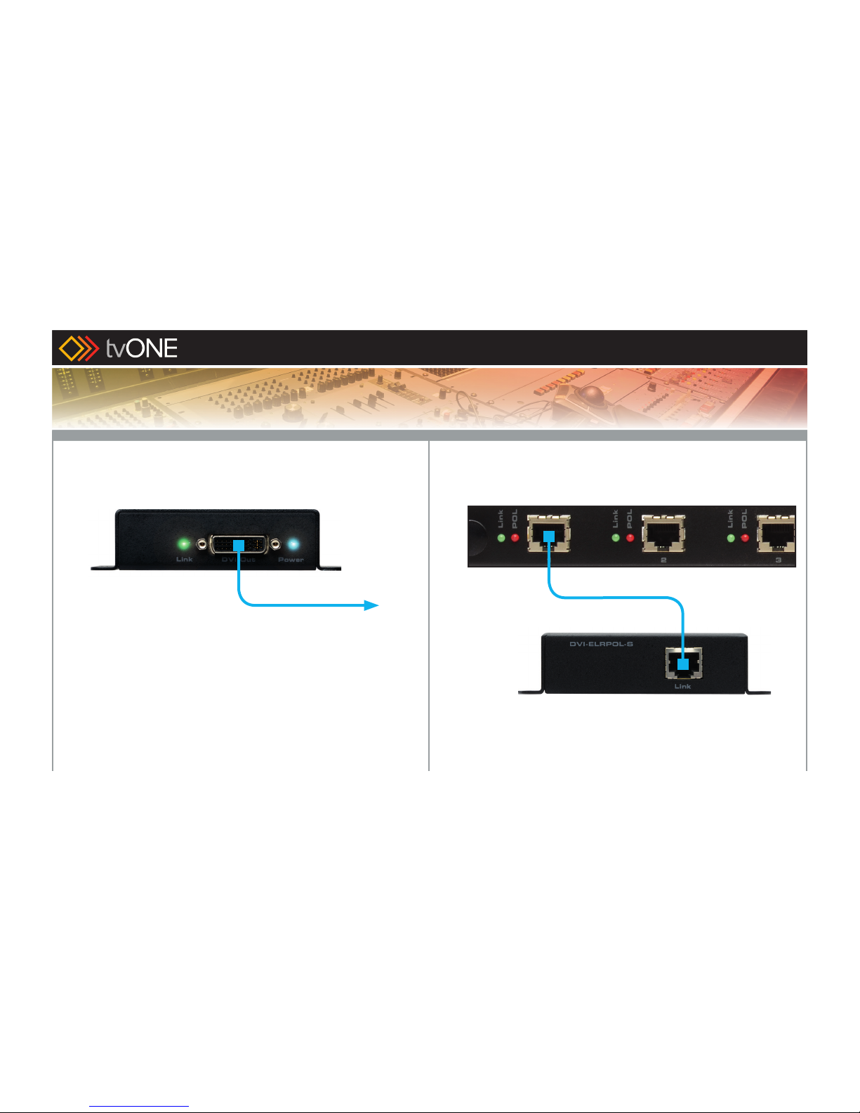
The input and output on each card is identified under each port.
Blue LEDs on each card indicate that the card is properly powered.
Consult the User Manual for additional information on the rear-panel layout.
1
1
Introduction
The 16x16 ModularMX Matrix
Quick Start Guide
Make sure you have everything that came with your product:
Refer to page 3 for the included items shipped with your product.
tvONE USA
2791 Circleport Drive, Erlanger, KY 41018
Telephone: 859-980-0420
Fax: 859-282-8225
Email: [email protected]
Visit us on the Web: www. tvone.com
Technical Support Hours: 8:00 AM to 5:00 PM Monday - Friday, EDT
tvONE EMEA
Unit V, Continental Approach, Westwood Ind Est, Margate, Kent CT9 4JG, UK
Telephone: +44 (0)1843 873322
Fax: +44 (0)1843 873301
Email: [email protected]
Visit us on the Web: www. tvone.com
Technical Support Hours: 8:00 AM to 5:30 PM Monday - Friday, GMT
For 24 / 7 support, see the back of the product for the support number
Refer to the last page of this Quick-Start Guide for contact information.
NOTE: For important operational details and warranty information,
refer to the User Manual, which can be downloaded from the Support
section of the tvONE Web site

Rear-Panel Layout
2
Power indicator Input slotsOutput slots
Quick Start Guide

3
The following list outlines the available pre-configured options. Since different
configurations may require different connections and set-up, it is important to
identify the type of 16x16 ModularMX Matrix you have purchased:
• MOD-16416-DVI
Two DVI input cards, providing a total of 16 DVI inputs.
Two DVI output cards, providing a total of 16 DVI outputs.
Package Includes:
(1) 16x16 ModularMX Matrix Frame
(1) DB-9 cable
(2) AC power cords
(2) ModularMX Matrix 8 DVI Input Cards
(2) ModularMX Matrix 8 DVI Output Cards
(1) Quick-Start Guide
• MOD-16416-DVIELR
Two DVI input cards, providing a total of 16 DVI inputs.
Two ELR-POL output cards, providing a total of 16 ELR-POL ports. Each
of these outputs are connected to a Receiver unit, using a CAT-5e cable,
allowing you to extend the DVI signal up to 330 feet (100 meters). 16 DVI
ELR-POL Receiver units are included with this package option. These
Receiver units are powered via the CAT-5e cable and do not need power
supplies.
Package Includes:
(1) 16x16 ModularMX Matrix Frame
(1) DB-9 Cable
(2) AC Power Cords
(2) ModularMX Matrix 8 DVI Input Cards
(2) ModularMX Matrix 8 DVI Sender over CAT-5 Cards
(16) DVI ELR Receivers with POL
(1) Quick-Start Guide
Quick Start Guide
Pre-configured Options 2

4
• MOD-16416-DPDVI
Two DisplayPort input cards, providing a total of 16 DisplayPort inputs.
Two DVI output cards, providing a total of 16 DVI outputs.
Package Includes:
(1) 16x16 ModularMX Matrix Frame
(1) DB-9 Cable
(2) AC Power Cords
(2) ModularMX Matrix 8 DisplayPort Input Cards
(2) ModularMX Matrix 8 DVI Output Cards
(1) Quick-Start Guide
• MOD-16416-ELR
Two ELR-POL input cards, providing a total of 16 ELR-POL ports.
Each of these inputs are connected to a Sender unit, using a CAT-5e cable,
allowing you to extend the DVI signal from a source up to 330 feet (100
meters). 16 DVI ELR-POL Sender units and 16 DVI ELR-POL Receiver units
are included with this package option.
Two ELR-POL output cards, providing a total of 16 ELR-POL ports.
Each of these outputs are connected to a Receiver unit, using a CAT-5e
cable, allowing you to extend the DVI signal up to 330 feet (100 meters).
The Sender and Receiver units are powered via the CAT-5e cable and do
not need power supplies.
Package Includes:
(1) 16x16 ModularMX Matrix Frame
(1) DB-9 Cable
(2) AC Power Cords
(2) ModularMX Matrix 8 ELR-POL Input Cards
(2) ModularMX Matrix 8 ELR-POL Output Cards
(16) DVI ELR-POL Senders
(16) DVI ELR-POL Receivers
(1) Quick-Start Guide
Quick Start Guide
Pre-configured Options (continued)

Pre-configured Options (continued)
5
• MOD-16416-DVI1FO
Two DVI input cards, providing a total of 16 DVI inputs.
Two Fiber Optic output cards, providing a total of 16 SC-type fiber optic
connectors. Each of these fiber optic ports are connected to a Receiver unit,
allowing you to extend the DVI signal up to 6600 feet (2000 meters) using
50μ OM3e/OM4 multimode fiber optic cable. OM3 and OM1 fiber are also
supported. See page 12 for distance limitations using other fiber optic cable
types. 16 fiber optic Receiver units and power supplies are included with this
package option.
Package Includes:
(1) 16x16 ModularMX Matrix Frame
(1) DB-9 Cable
(2) AC Power Cords
(2) ModularMX Matrix 8 DVI Input Cards
(2) ModularMX Matrix 8 Fiber Optic Output Cards
(16) DVI Receivers over 1FO
(16) 5V Power Supplies for the above
(1) Quick-Start Guide
• MOD-16416-DPELR
Two DisplayPort input cards, providing a total of 16 DisplayPort inputs.
Two ELR-POL output cards, providing a total of 16 ELR-POL ports. Each
of these outputs are connected to a Receiver unit, using a CAT-5e cable,
allowing you to extend the DVI signal up to 330 feet (100 meters). 16 DVI
ELR-POL Receiver units are included with this package option. These
Receiver units are powered via the CAT-5e cable and do not need power
supplies.
Package Includes:
(1) 16x16 ModularMX Matrix Frame
(1) DB-9 Cable
(2) AC Power Cords
(2) ModularMX Matrix 8 DisplayPort Input Cards
(2) ModularMX Matrix 8 ELR-POL Output Cards
(16) DVI ELR-POL Receivers
(1) Quick-Start Guide
Quick Start Guide

Pre-configured Options (continued)
6
• MOD-16416-DP1FO
Two DisplayPort input cards, providing a total of 16 DisplayPort inputs.
Two Fiber Optic output cards, providing a total of 16 SC-type fiber optic
connectors. Each of these fiber optic ports are connected to a Receiver unit,
allowing you to extend the DisplayPort signal up to 6600 feet (2000 meters)
using 50μ OM3e/OM4 multimode fiber optic cable. OM3 and OM1 fiber are
also supported. See page 12 for distance limitations using other fiber optic
cable types. 16 fiber optic Receiver units and power supplies are included
with this package option.
Package Includes:
(1) 16x16 ModularMX Matrix Frame
(1) DB-9 Cable
(2) AC Power Cords
(2) ModularMX Matrix 8 DisplayPort Input Cards
(2) ModularMX Matrix 8 Fiber Optic Output Cards
(16) DVI Receivers over 1FO
(16) 5V Power Supplies for the above
(1) Quick-Start Guide
• MOD-16416-1FO
Two Fiber Optic input cards, providing a total of 16 SC-type fiber optic
connectors. Each of these fiber optic ports are connected to a Sender unit,
allowing you to extend the DVI signal from a source up to 6600 feet (2000
meters) using 50μ OM3e/OM4 multimode fiber optic cable. 16 fiber optic
Sender units and 16 Receiver units are included with this package option.
Two Fiber Optic output cards, providing a total of 16 SC-type fiber optic
connectors. Each of these fiber optic ports are connected to a Receiver unit,
allowing you to extend the DVI signal up to 6600 feet (2000 meters) using
50μ OM3e/OM4 multimode fiber optic cable.
OM3 and OM1 fiber are also supported. See page 12 for distance limitations
using other fiber optic cable types.
Package Includes:
(1) 16x16 ModularMX Matrix Frame
(1) DB-9 Cable
(2) AC Power Cords
(2) ModularMX Matrix 8 Fiber Optic Input Cards
(2) ModularMX Matrix 8 Fiber Optic Output Cards
(16) DVI Senders over 1FO
(16) DVI Receivers over 1FO
(32) 5V Power Supplies for the above
(1) Quick-Start Guide
Quick Start Guide

7
Connections
MOD-16416-DVI
1. Connect up to 16 DVI sources to the DVI inputs.
2. Connect up to 16 DVI displays to the DVI outputs using DVI cables.
3. Connect both AC power cords from the matrix to available electrical outlets.
Connecting both AC power cords will provide power redundancy should
one of the power supplies fail. It is recommended to connect each AC power
cord to separate circuits.
1. Connect up to 16 DVI sources the DVI inputs.
2. Connect a CAT-5e cable (or better), up to 330 feet (100 meters) from each
ELR-POL port on the Output card to each of the included ELR-POL Receiver
units, as shown below.
Once the matrix is powered, the Link indicators will glow bright green to
indicate a solid link between the output card and the Receiver unit.
The POL indicators will glow bright amber to indicate that the Receiver unit
is being powered.
MOD-16416-DVIELR
Quick Start Guide
3

1. Connect a CAT-5e cable (or better), up to 330 feet (100 meters) from each
ELR-POL input to each of the included DVI ELR-POL Sender units, as shown
below.
8
3. Connect a DVI cable from the DVI Out port on the ELR-POL Receiver unit to
a DVI display.
4. Connect both AC power cords from the matrix to available electrical outlets.
Connecting both AC power cords will provide redundancy should one of
the power supplies fail. It is recommended to connect each power cord to
electrical outlets on two separate circuits.
Power to the Receiver unit is delivered from the power supply in the matrix
over the CAT-5e cable using Power Over Line (POL) technology.
The Link indicator will glow bright green to indicate a solid connection
between the matrix and the Receiver unit. The Power indicator will glow
bright blue to indicate that the Receiver unit is being powered.
If either of these LED indicators are off, inspect the CAT-5 cable.
MOD-16416-DVIELR (continued)
to DVI display
DVI-ELRPOL-R
MOD-16416-ELR
CAT-5e (or better) cable up to
330 feet (100 meters)
Quick Start Guide

2. Connect a DVI source to the DVI input of each DVI ELR-POL Sender unit.
3. Connect a CAT-5e cable (or better), up to 330 feet (100 meters) from each
ELR-POL output to each of the included DVI ELR-POL Receiver units.
4. Connect a DVI display to each Receiver unit.
5. Connect both AC power cords from the matrix to available electrical outlets.
Connecting both AC power cords will provide redundancy should one of
the power supplies fail. It is recommended to connect each power cord to
electrical outlets on two separate circuits.
Power to the Sender and Receiver units are delivered from the power
supply in the matrix over the CAT-5e cable using Power Over Line (POL)
technology. The Link indicator will glow bright green to indicate a solid
connection between the matrix and the Receiver unit. The Power indicator
will glow bright blue to indicate that the Receiver unit is being powered. If
either of these LED indicators are off, inspect the CAT-5 cable.
DVI cable (to display)
DVI-ELRPOL-R
MOD-16416-ELR (continued)
9
Quick Start Guide

MOD-16416-DPDVI
NOTE: This package is similar to the DVI package, except for the fact that all
inputs will be DisplayPort instead of DVI. Refer to the connection instructions for
the DVI version of each package if needed.
1. Connect the up to 16 DisplayPort sources to the DisplayPort inputs on the
matrix.
2. Connection up to 16 displays to the DVI outputs on the matrix using DVI
cables.
3. Power up the matrix.
MOD-16416-DPELR
NOTE: This package is similar to the DVIELR package, except for the fact that all
inputs will be DisplayPort instead of DVI. Refer to the connection instructions for
the DVIELR version of each package if needed.
1. Connect up to 16 DisplayPort sources to the DisplayPort inputs.
2. Connect a CAT-5e cable (or better), up to 330 feet (100 meters) from each
ELR-POL port on the Output card to each of the included ELR-POL Receiver
units.
3. Connect a DVI cable from the DVI Out port on the ELR-POL Receiver unit to
a DVI display.
4. Connect both AC power cords from the matrix to available electrical outlets.
Connecting both AC power cords will provide redundancy should one of
the power supplies fail. It is recommended to connect each power cord to
electrical outlets on two separate circuits.
Power to the Receiver unit is delivered from the power supply in the matrix
over the CAT-5e cable using Power Over Line (POL) technology.
The Link indicator will glow bright green to indicate a solid connection
between the matrix and the Receiver unit. The Power indicator will glow
bright blue to indicate that the Receiver unit is being powered.
If either of these LED indicators are off, inspect the CAT-5 cable.
10
Quick Start Guide

50μ OM3e/OM4, OM3, and 62.5μ OM1 multimode fiber optic cable can be
used. However, the maximum extension distance is dependent upon the
type of fiber optic cable used:
• 6600 feet (2000 meters) using 50μ OM3e/OM4 multimode fiber optic cable.
• 2000 feet (600 meters) using 50μ OM3 multimode fiber optic cable.
• 660 feet (200 meters) using 62.5μ OM1 multimode fiber optic cable.
3. Connect a DVI cable from the DVI Out port on the Receiver unit to a display.
4. Connect the power supply to the 1FO Receiver unit and to an available
electrical outlet.
to DVI display
DVI-1FO-R
MOD-16416-DVI1FO
1. Connect the up to 16 DVI sources to the DVI inputs on the matrix.
2. Connect a single strand of SC-terminated multimode fiber optic cable from
each SC connector on the Output Card to each Receiver unit.
Multimode Fiber Optic cable Up to 6600
feet (2000 meters)
11
Quick Start Guide

MOD-16416-1FO
5. Connect both AC power cords from the matrix to available electrical outlets.
Connecting both AC power cords will provide power redundancy should
one of the power supplies fail. It is recommended to connect each AC power
cord to separate circuits.
The Link indicator will glow bright green to indicate a connection between
the matrix and the Receiver unit. If this LED is off, inspect the fiber optic
cable for defects.
The Power indicator will glow bright blue to indicate that the Receiver unit is
powered.
MOD-16416-DVI1FO (continued)
1. Using single strand SC-terminated multimode fiber optic cables, connect up
to 16 DVI Fiber Optic Sender Units to the SC connectors on the input card,
up to 6600 feet (2000 meters) away.
Make sure to remove the protective covers before connecting the fiber optic
cable.
Multimode Fiber Optic cable Up to 6600
feet (2000 meters)
Quick Start Guide
12

13
MOD-16416-1FO (continued)
50μ OM3e/OM4, OM3, and 62.5μ OM1 multimode fiber optic cable can be
used. However, the maximum extension distance is dependent upon the
type of fiber optic cable used:
• 6600 feet (2000 meters) using 50μ OM3e/OM4 multimode fiber optic cable.
• 2000 feet (600 meters) using 50μ OM3 multimode fiber optic cable.
• 660 feet (200 meters) using 62.5μ OM1 multimode fiber optic cable.
2. Connect a DVI source to the DVI input of each DVI Fiber Optic Sender unit.
3. Using single strand SC-terminated multimode fiber optic cables, connect up
to 16 DVI Fiber Optic Receiver Units to the SC connectors of the ModularMX
Matrix Fiber Output Card.
4. Connect a DVI display to each Receiver unit.
5. Connect the locking power supply to the Sender and Receiver units and to
available electrical outlets. The Power LED indicators will glow bright blue
when both units are powered-on.
Connect both AC power cords from the matrix to available electrical outlets.
This will provide power redundancy should one of the power supplies fail. It
is recommended to connect each AC power cord to separate circuits.
The Link LED’s on the modular
When the Sender and Receiver units are powered-on, the Link LED
indicators will glow bright green to indicate a connection between the matrix
and the Sender and Receiver units. If this LED is off, inspect the fiber optic
cable for defects.
to DVI display
DVI-1FO-R
Quick Start Guide

14
MOD-16416-DP1FO
NOTE: This package is similar to the DVI1FO package, except for the fact that all
inputs will be DisplayPort instead of DVI. Refer to the connection instructions for
the DVI1FO version if needed.
1. Connect the up to 16 DisplayPort sources to the DisplayPort inputs on the
matrix.
2. Connect a single strand of SC-terminated multimode fiber optic cable from
each SC connector on the Output Card to each Receiver unit.
3. Connect a DVI cable from the DVI Out port on the Receiver unit to a display.
4. Connect the power supply to the 1FO Receiver unit and to an available
electrical outlet.
5. Connect both AC power cords from the matrix to available electrical outlets.
Connecting both AC power cords will provide power redundancy should
one of the power supplies fail. It is recommended to connect each AC power
cord to separate circuits.
The Link indicator will glow bright green to indicate a connection between
the matrix and the Receiver unit. If this LED is off, inspect the fiber optic
cable for defects.
Quick Start Guide

Although each 16x16 ModularMX Matrix is available pre-configured, both input and
output cards can be added or replaced to fit the needs of your application.
Each card can easily be removed and installed without using any special tools.
1. Power OFF the matrix and disconnect all cables from the card you are
planning to remove.
2. Turn the matrix around so the back of the unit is facing you.
3. Loosen the fastening screws on both sides of the card (or cover plate) to be
removed. Each card / cover plate has two fastening screws.
4. Grab the knobs on both sides of the card, between the thumb and index
finger, and gently pull to remove the card from the matrix (cover plates do
not have pull-knobs).
WARNING: Cards are sensitive to Electrostatic Discharge (ESD)
which can damage the card. Avoid touching the card contacts
or the components on the card. Always hold cards by the edges
or by the knobs on the front of the card. Never slide a card over
any surface. When installing/replacing cards, do not try to install
an input card in an output slot (or vice versa) and do not force
the cards into place. This will damage the matrix and void the
warranty.
STOP: Before installing or removing cards and to prevent the
risk of possible electrical shock, unplug both of the AC power
cords from the power supply(s) on the back of the matrix.
Removing and Installing Cards
Removing Cards
15
Quick Start Guide
4

16
Installing Cards
1. Locate the metal track on either side of the expansion slot.
2. Carefully position the card between the upper and lower rail on each track
and slowly push the card forward.
3. Secure the card by hand-tightening the fastening screws. Do not overtighten
the screws. To prevent damage to the screws, do not use
pliers or other high-torque devices.
Quick Start Guide

www.tvone.com

16x16 ModularMX is a trademark of tvONE
tvONE reserves the right to make changes in the hardware, packaging, and any accompanying documentation without prior written notice.
© 2014 tvONE. All rights reserved.
All trademarks are the property of their respective owners.
Features and specifications are subject to change without notice.
Pb
This product uses UL listed or CE compliant power supplies.
tvONE USA
2791 Circleport Drive, Erlanger, KY 41018 USA
800-721-4044 fax: 859-282-8225
tvONE EMEA
Continental Approach, Westwood Ind. Est., Margate, Kent CT9 4JG UK
+44 (0)1843 873311 fax: +44 (0)1843 873312
www. tvone.com
This manual suits for next models
7
Table of contents
Other TV One Matrix Switcher manuals

TV One
TV One MX-65 Series User manual

TV One
TV One MX-6388 User manual

TV One
TV One MX-8488 User manual

TV One
TV One IM-400 Series User manual

TV One
TV One MOD-32432-DVI1FO User manual

TV One
TV One MX-5288 User manual

TV One
TV One MX-8488 User manual

TV One
TV One MX-5288 User manual

TV One
TV One MX-2522 User manual

TV One
TV One MX-6388 User manual