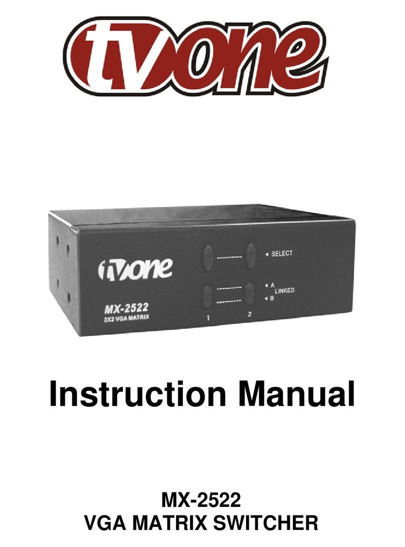
TV One MOD-32432-DVI1FO User manual

32 32
x
SOURCES DISPLAYS
ModularMX
V 1.0
User Manual
MOD-32432-DVI • MOD-32432-DVIELR
MOD-32432-DVI1FO • MOD-32432-DPDVI
MOD-32432-DPELR • MOD-32432-DP1FO
1080P


ASKING FOR ASSISTANCE
USA
tvONE
2791 Circleport Drive
Erlanger, KY 41018
Telephone: 859-980-0420
Fax: 859-282-8225
Email: [email protected]
Visit us on the Web: www. tvone.com
Technical Support Hours: 8:00 AM to 6:00 PM Monday - Friday, Eastern Time
EMEA
tvONE
Unit V, Continental Approach, Westwood Industrial Estate
Margate, Kent CT9 4JG, UK
Telephone: +44 (0)1843 873322
Fax: +44 (0)1843 873301
Email: [email protected]
Visit us on the Web: www. tvone.com
Technical Support Hours: 8:00 AM to 5:30 PM Monday - Friday, GMT
For 24 / 7 support, see the back of the product for the support number
Notice
tvONE reserves the right to make changes in the hardware, packaging and any
accompanying documentation without prior written notice.
32x32 ModularMX is a trademark of tvONE,
All trademarks are the property of their respective companies.
© 2014 tvONE, All Rights Reserved
All trademarks are the property of their respective companies

CONTENTS
INTRODUCTION....................................................................................................................1
Features..........................................................................................................................2
Package Includes............................................................................................................2
Pre-ConguredOptions..................................................................................................3
Front Panel Layout.........................................................................................................8
Front Panel Descriptions.................................................................................................9
Back Panel Layout........................................................................................................10
Back Panel Descriptions...............................................................................................11
CONNECTING THE 32x32 ModularMX.............................................................................12
Connections..................................................................................................................12
Wiring Diagram.............................................................................................................12
DisplayPort package options........................................................................................17
OPERATING THE 32x32 ModularMX................................................................................18
Booting Up / Standby Screen........................................................................................18
Displaying the current Routing State............................................................................19
Routing Sources...........................................................................................................20
Locking the Matrix.........................................................................................................22
Using the Cancel button................................................................................................23
Cycling between Information Screens..........................................................................24
Saving the current Routing State..................................................................................25
Recalling a stored Routing State..................................................................................27
Masking Outputs...........................................................................................................29
EDID Management.......................................................................................................31
Saving the Downstream EDID to Local memory....................................................31
Saving the Default EDID to Local memory.............................................................33
RS-232 / IP CONTROL........................................................................................................35
RS-232 Interface...........................................................................................................35
RS-232 Settings............................................................................................................35
ConguringtheIPAddress...........................................................................................36
RS-232 / Telnet Commands..........................................................................................37
EDID Management...............................................................................................37
IPConguration....................................................................................................47
Routing and Masking............................................................................................55
System..................................................................................................................65
Using the Built-in Web server........................................................................................73
Routing..................................................................................................................73
Routing.........................................................................................................73
Preset Names...............................................................................................77
I/O Names....................................................................................................78
+5V...............................................................................................................79
Output Masks...............................................................................................81

CONTENTS
Status....................................................................................................................83
In / Out..........................................................................................................83
System.........................................................................................................84
Manage EDID.......................................................................................................85
Assign...........................................................................................................85
Bank Names.................................................................................................87
Upload / Download.......................................................................................88
Conguration.........................................................................................................89
APPENDIX............................................................................................................................93
Card Removal and Installation......................................................................................93
Firmware Update Procedure.........................................................................................96
RACK MOUNT SAFETY INFORMATION..........................................................................100
SPECIFICATIONS..............................................................................................................101
WARRANTY........................................................................................................................102
LICENSING.........................................................................................................................103

IMPORTANT OPERATING NOTES
READ THESE NOTES BEFORE INSTALLING OR OPERATING
THE 32X32 MODULARMX
• There is no internal scaling in the 32x32 ModularMX. All of the attached monitors
must be able to display the output resolutions of the source devices. For maximum
compatibility it is recommended that only one compatible/common resolution be used
by all of the source devices.
• Routing features can be accessed using the serial control interface or via Telnet.
See page 37 - 74 for more information.
• The 32x32 ModularMX has several The tvONE 32x32 ModularMX provides several
differentpre-conguredpackagestosuittheneedsofyourapplication.
ThisUserManualcoversallavailablecongurations.Seepage3forinformation
on identifying the type of 32x32 ModularMX that was purchased.

1
Congratulations on your purchase of the 32x32 ModularMX. Your complete satisfaction is
very important to us.
tvONE
In the realm of video distribution, certain features are invaluable in a commercial or
broadcastenvironment.Accommodationssuchasabuild-inpowersupplyandatblack
rack-mount enclosures set tvONE apart from our traditional products. Complex distribution
units allow for professional DVI, 3G-SDI, and HDMI signals to be routed and converted
easily and seamlessly, while being backed up by a renowned and dependable technical
supportteam.tvONEinvitesyoutoexplorethetvONEproductlineandhopesthatyound
thesolutionthattsyourneeds.
The tvONE 32x32 ModularMX
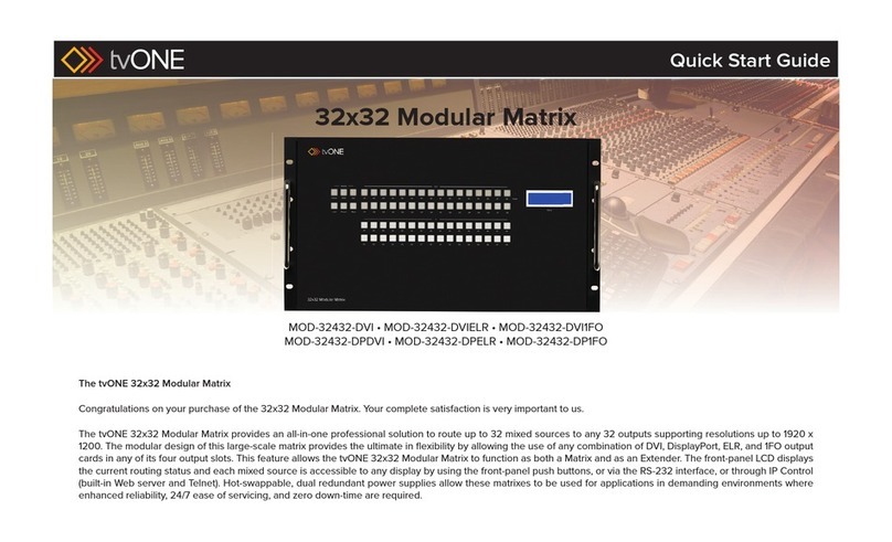
The tvONE 32x32 ModularMX provides an all-in-one professional-grade solution to route
up to 32 DVI sources to up to 32 DVI displays with resolutions up to 1920 x 1200. The
modulardesignofthismatrixprovidestheultimateinexibilitybyallowingtheuseofany
combination of DVI, ELR, or 1FO output modules in any of its four output slots. This feature
allows the tvONE 32x32 ModularMX to function as both a Matrix and as an Extender. The
front-panel LCD displays the current routing status and each DVI source is accessible to
any display by using the front-panel push buttons, via the RS-232 interface, or through IP
Control (built-in Web server and Telnet). Hot-swappable dual redundant power supplies
allow these matrixes to be used for applications in demanding applications where enhanced
reliability, ease of servicing and zero down-time are required.
How It Works
Connect up to 32 DVI source devices using DVI cables to the inputs on the tvONE
ModularMX. Connect up to 32 displays via DVI, CAT-5, or Fiber Optic cables depending
on which output modules are utilized. Connect an Ethernet cable from the network to the
RJ-45 connector to use the built-in Web server or Telnet capability to control routing, EDID,
and other functions. Connect an RS-232 cable from a RS-232 control device to control
the matrix via RS-232. Connect the IEC connectors of the included AC power cords to the
matrix and plug the power cords into available electrical outlets. The DVI sources will be
routed as selected.
INTRODUCTION

2
INTRODUCTION
Features
• Supports resolutions up to 1920 x 1200
• Modular inputs and outputs organized into banks of 8 input or output devices
• Advanced EDID management for rapid integration of sources and displays
• RS-232 Serial interface for remote control via a computer or automation control
system
• Front-panel LCD display
• Front-panel push buttons for local switching
• Built-in Web server, Telnet, and UDP control via IP
• Routing states can be stored and recalled at the touch of a button
• Dual redundant hot-swappable power supplies
• Removableandreplaceablefanandlter
• Output masking command
• Standby mode
• Power ON / OFF switch
• Rack-mountable
Package Includes
Seetheinformationbeginningonthenextpagefordetailsontheavailablepre-congured
options.
Ifanyoftheitemsfromthepre-conguredpackagesaremissing,calltvONETechnical
Support between the hours of 8:00 AM and 5:00 PM, Monday through Friday, EDT in the
USA or 8:00 AM to 5:30 PM Monday - Friday, GMT in Europe.

3
INTRODUCTION
Pre-Congured Options
Before reading this User Manual, familiarize yourself with the rear panel of the 32x32
ModularMX.
The 32x32 ModularMX can accommodate up to four input cards and four output
cards. Each card provides eight connectors, providing a total of 32 inputs and outputs.
The32x32ModularMXissoldpre-conguredwithacombinationofinputandoutputcards
bestsuitedfortheneedsofyourapplication.Wewillcovereachcongurationin
the next section. First, we will identify the location of each input and output card on the
matrix.
Matrix Layout
The bottom-four expansion bays of the matrix only accept input cards. The top-four
expansion bays only accept outputcards.Eachexpansionbayonthematrixisidentied
with a letter: A, B, C, and D, from top to bottom (see next page).
The inputs and outputs are numbered on each card, from left-to-right.
Blue LEDs on each card indicate that the card is properly powered.
Refer to page 10 for detailed information on the rear-panel layout.
NOTE: When a card is not installed, it is recommended that a cover
plate be installed over the expansion bay to prevent dust and other
foreign particles from entering the matrix.
Output bays
Cover plate Power indicator

4
INTRODUCTION
Thefollowinglistoutlinestheavailablepre-conguredoptions.BecausethisUserManual
coversinformationonallavailablecongurations,itisimportanttoidentifythetypeof
32x32 ModularMX that you have purchased:
• MOD-32432-DVI
Four input cards. Each card contains eight DVI inputs, providing a total of 32 DVI
inputs.
Four output cards. Each card contains eight DVI outputs, providing a total of 32 DVI
outputs.
Package Includes:
(1) 32x32 ModularMX Frame
(1) DB-9 cable
(2) AC power cords
(4) ModularMX 8 DVI Input Cards
(4) ModularMX 8 DVI Output Cards
(1) Quick-Start guide
Input bays
87
A
B
C
D

5
INTRODUCTION
• MOD-32432-DVIELR
Four input cards. Each card contains eight DVI inputs, providing a total of 32 DVI
inputs.
Four output cards. Each card contains eight ELR-POL outputs. Each of these ELR-
POL outputs are connected to a Receiver unit, using a CAT-5e cable, allowing you to
extend the DVI signal up to 330 feet (100 meters). 32 ELR-POL Receiver units are
included with this package option.
Package Includes:
(1) 32x32 ModularMX Frame
(1) DB-9 Cable
(2) AC Power Cords
(4) ModularMX 8 DVI Input Cards
(4) ModularMX 8 DVI Sender over CAT-5 Cards
(32) DVI ELR Receivers with POL
(1) Quick-Start guide
• MOD-32432-DPDVI
Four input cards. Each card contains eight DisplayPort inputs, providing a total of 32
DisplayPort inputs.
Four output cards. Each card contains eight DVI outputs, providing a total of 32 DVI
outputs.
Package Includes:
(1) 32x32 ModularMX Frame
(1) DB-9 Cable
(2) AC Power Cords
(4) ModularMX 8 DisplayPort Cards
(4) ModularMX 8 DVI Output Cards
(1) Quick-Start guide

6
• MOD-32432-DPELR
Four input cards. Each card contains eight DisplayPort inputs, providing a total of 32
DisplayPort inputs.
Four output cards. Each card contains eight ELR-POL outputs. Each of these ELR-
POL outputs are connected to a Receiver unit, using a CAT-5e cable, allowing you
to extend the DisplayPort signal up to 330 feet (100 meters). 32 ELR-POL Receiver
units are included with this package option.
Package Includes:
(1) 32x32 ModularMX Frame
(1) DB-9 Cable
(2) AC Power Cords
(4) ModularMX 8 DisplayPort Cards
(4) ModularMX 8 DVI Sender over CAT-5 Cards
(32) DVI ELR Receivers with POL
(1) Quick-Start guide
• MOD-32432-DVI1FO
Four input cards. Each card contains eight DVI inputs, providing a total of 32 DVI
inputs.
Fouroutputcards.EachcardcontainseightSC-typeberopticconnectors.Eachof
theseberopticconnectorsareconnectedtoaReceiverunit,allowingyoutoextend
theDVIsignalupto6600feet(2kilometers)using50μOM3emultimodeberoptic
cable.OM3andOM1berarealsosupported.32beropticReceiverunitsare
included with this package option.
Package Includes:
(1) 32x32 ModularMX Frame
(1) DB-9 Cable
(2) AC Power Cords
(4) ModularMX 8 DVI Input Cards
(4) ModularMX 8 DVI Sender over 1FO Cards
(32) DVI Modular Receivers over 1FO
(32) Power supplies for DVI Modular Receivers over 1FO
(1) Quick-Start guide
INTRODUCTION

7
INTRODUCTION
• MOD-32432-DP1FO
Four input cards. Each card contains eight DisplayPort inputs, providing a total of 32
DisplayPort inputs.
Fouroutputcards.EachcardcontainseightSC-typeberopticconnectors.Eachof
theseberopticconnectorsareconnectedtoaReceiverunit,allowingyoutoextend
theDisplayPortsignalupto6600feet(2kilometers)using50μOM3emultimodeber
opticcable.OM3andOM1berarealsosupported.32beropticReceiverunitsare
included with this package option.
Package Includes:
(1) 32x32 ModularMX Frame
(1) DB-9 Cable
(2) AC Power Cords
(4) ModularMX 8 DisplayPort Input Cards
(4) ModularMX 8 DisplayPort Sender over 1FO Cards
(32) DVI Modular Receivers over 1FO
(32) Power supplies for DVI Modular Receivers over 1FO
(1) Quick-Start guide

8
tvONE
32x32 ModularMX
INTRODUCTION
2
5
3 41
Front Panel Layout

9
INTRODUCTION
Front Panel Descriptions
1 Mode Buttons
These buttons are used to control other features on the product. See pages 22 - 36 for
more information.
2 Output Buttons (1 - 32)
Used for routing an Input to an Output. Each of these buttons represents an Output.
See page 22 for more information on routing DVI sources.
3 Power Indicator
This LED indicator will glow red when the power is turned on.
4 LCD Display
Displays the current routing status of the Matrix and is also used to manage source
routing.
5 Input Buttons (1 - 32)
Used for routing an Input to an Output. Each of these buttons represents an Input.
See page 22 for more information on routing DVI sources.

10
Back Panel Layout
INTRODUCTION
1
4
3
5 10
678
2
9

11
INTRODUCTION
Back Panel Descriptions
1 Out (1 - 32)
Connect the output devices to these ports. Output banks are shown using the
tvONE ELR-POL Extender (DVI-8ELR-S), the tvONE Fiber Optic Extender (DVI-1FO-S),
and the tvONE DVI Output Board (MOD-8DVI-O).
2 Power (Input / Output boards)
Each Input and Output card has its own power indicator. This LED indicator will glow
bright blue when the card is properly installed and the power to the 32x32 ModularMX is
applied.
3 Cover Plate
In the event that an Output (or Input) board is not required, the cover plate can be installed
to prevent foreign particles or objects from entering the system.
4 In (1 - 32)
Connect the source devices to each of these ports. At the time of this writing, only DVI
input modules are available.
5 RS-232 Serial Port
Connects to the RS-232 control device. The 32x32 ModularMX may be switched remotely
using this port. See page 37 - 74 for more information.
6 IP / UDP / Telnet Control
Connect the 32x32 ModularMX to a network in order to use IP / UDP / Telnet control.
7 IR
Connect an IR extender to this IR port.
8 Power
This LED indicator glows bright blue when the matrix is powered on.
9 Power Supply (1 - 2)
Connect the included AC power cords from these receptacle to an available electrical
outlet. The redundant (secondary) power cable should be connected to an electrical outlet
on a different circuit. Each power supply is 110/220V AC.
10 Grounding Terminal
Provides a discharge path to ground in case a short circuit occurs between the “hot”
lead of the power supply and the enclosure of the Matrix. The grounding wire should be
attached from the grounding terminal to an approved ground path.
NOTE: Depending upon the package option of the 32x32 Modu-
larMX that was purchased, the back-panel may differ.

12
Connections
Because there are several variations of the 32x32 ModularMX, we will cover each package
option. Locate the connection instructions for the package which was purchased. The
wiring diagram at the bottom of the page provides a general reference for connecting the
32x32 ModularMX. See the following pages for detailed connection instructions on each
package option.
• MOD-32432-DVI..................................................................................13
• MOD-32432-DVIELR...........................................................................13
• MOD-32432-DVI1FO...........................................................................14
• MOD-32432-DPDVI.............................................................................17
• MOD-32432-DPELR............................................................................17
• MOD-32432-DP1FO............................................................................17
Wiring Diagram
MOD-32432
DVI CABLE
Total DVI Output Combinations*
32x32 Modular Matrix
DVI or DisplayPort Sources*
Up to
32x
Up to
32x
DVI-ELRPOL-R
Receivers
DVI-1FO-R
Receivers
DVI-ELRPOL-S
Senders
DVI-1FO-S
Senders
CAT-5 CABLE
FIBER OPTIC (SC-SC) CABLE
DISPLAYPORT CABLE
* Connection type determined by input or output card type
CONNECTING THE 32X32 MODULARMX
WARNING: This product should always be connected to a
grounded electrical socket.

13
1. Connect up to 32 DVI sources to the DVI inputs on the rear panel of the 32x32
ModularMX using DVI cables.
2. Connect up to 32 DVI displays to the DVI outputs on the rear panel of the 32x32
ModularMX.
3. Connect both AC power cords from the 32x32 ModularMX to available electrical
outlets. Connecting both AC power cords will provide redundancy should one of
the power supplies fail. It is recommended to connect each power cord to electrical
outlets on two separate circuits.
1. Connect up to 32 DVI sources to the DVI inputs on the rear panel of the 32x32
ModularMX using DVI cables.
2. Connect a CAT-5e cable (or better), up to 330 feet (100 meters) from each ELR-POL
jack on the Sender card to each of the included ELR-POL Receiver units, as shown
below.
Once the matrix is powered, the Link indicators will glow bright green to indicate a
solid link between the output card and the Receiver unit.
The POL indicators will glow bright amber to indicate that the Receiver unit is being
powered.
(continued on next page)
CONNECTING THE 32X32 MODULARMX
MOD-32432-DVI
MOD-32432-DVIELR
CAT-5e cable
Up to 330 feet (100 meters)
DVI-ELRPOL-R
DVI-8ELR-S

14
CONNECTING THE 32X32 MODULARMX
3. Connect a DVI cable from the DVI Out port on each ELR-POL Receiver unit to a DVI
display.
4. Connect both AC power cords from the 32x32 ModularMX to available electrical
outlets. Connecting both AC power cords will provide redundancy should one of
the power supplies fail. It is recommended to connect each power cord to electrical
outlets on two separate circuits.
Power to the Receiver unit is delivered from the power supply in the matrix over the
CAT-5e cable using tvONE Power Over Line (POL) technology. The Link indicator will
glow bright green to indicate a solid connection between the matrix and the Receiver
unit. The Power indicator will glow bright blue to indicate that the Receiver unit is
being powered.
If either of these LED indicators are OFF, inspect the CAT-5 cable for loose
connections or possible defects.
1. Connect up to 32 DVI sources to the DVI inputs on the rear panel of the 32x32
ModularMX using DVI cables.
2. ConnectasinglestrandofSC-terminated50μOM3emultimodeberopticcablefrom
each SC connector on the Sender card to each Receiver unit, as shown below:
MOD-32432-DVI1FO
DVI cable
DVI display
DVI-ELRPOL-R
Multimode Fiber Optic cable
Up to 6600 feet (2 kilometers)
DVI-1FO-R
MOD-8FO-S
This manual suits for next models
5
Table of contents
Other TV One Matrix Switcher manuals

TV One
TV One MX-5288 User manual

TV One
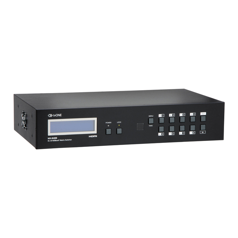
TV One MX-8488 User manual

TV One
TV One MX-5288 User manual

TV One
TV One MX-8488 User manual

TV One
TV One MOD-32432-DVI User manual

TV One
TV One 1T-MX-3344 User manual

TV One
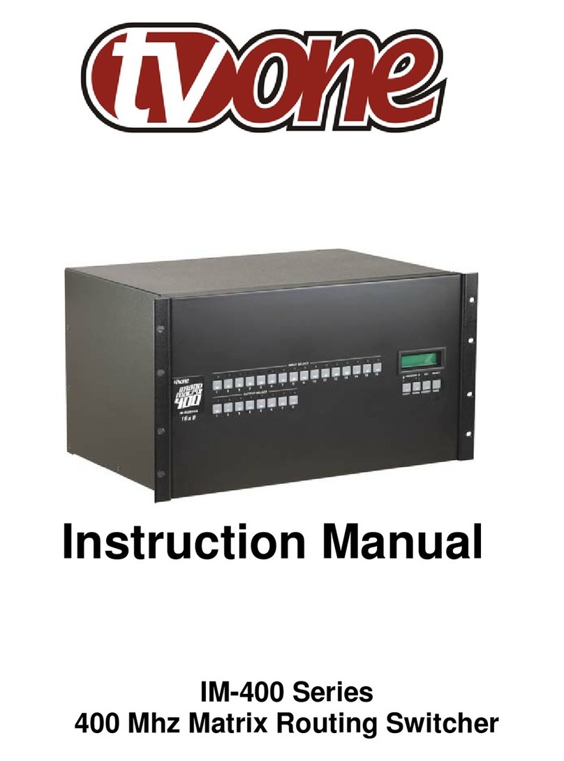
TV One IM-400 Series User manual

TV One
TV One 1T-MX-6344 User manual

TV One
TV One MOD-16416-DVI User manual

TV One
TV One MX-6388 User manual