twin busch TW F-50 T Instructions for use


Technical changes for purposes of a technical advancement as well as deviation in colour, errors and printing mistakes are reserved. 2

Technical changes for purposes of a technical advancement as well as deviation in colour, errors and printing mistakes are reserved. 3
Index
1. Summary of the balancing machine.................................................................... 4
A. Brief introduction of appearance ................................................................. 4
B. Performance and characteristics................................................................. 5
C. Technical data table ...................................................................................... 6
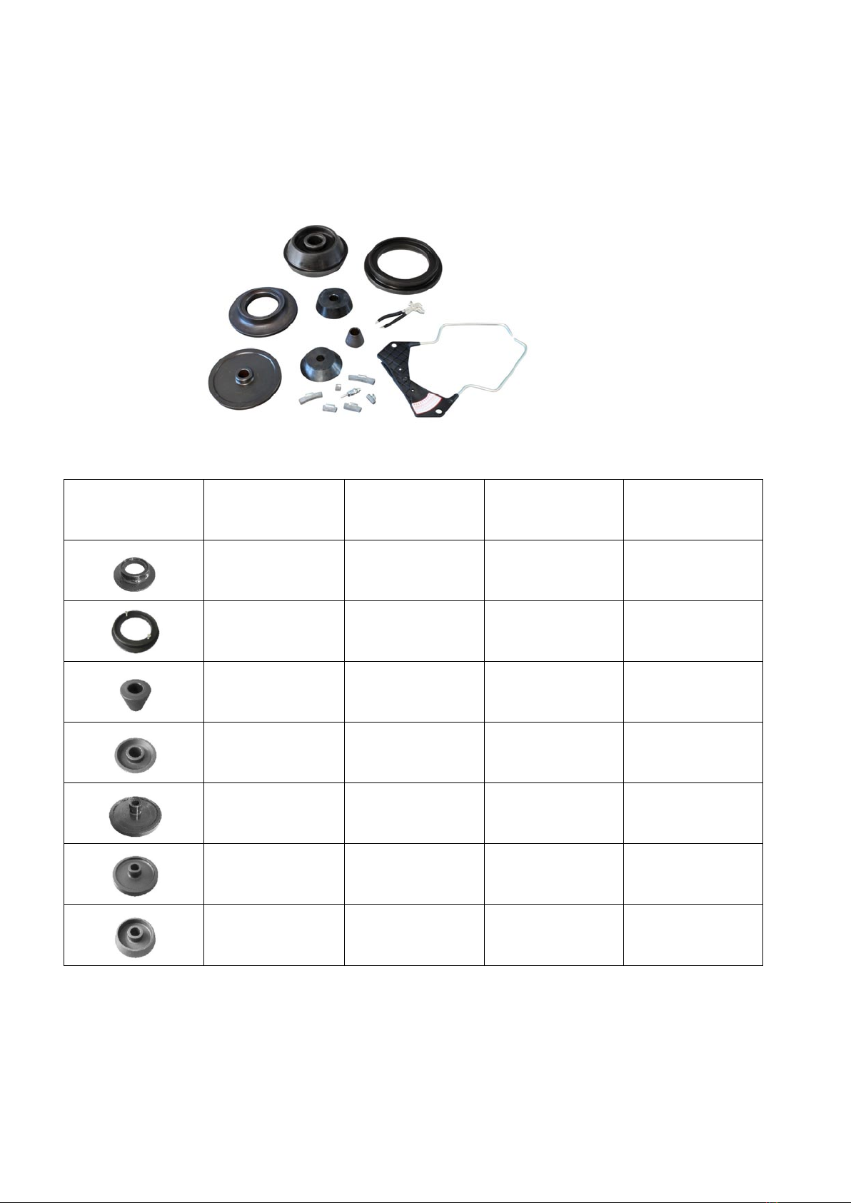
2. Accessories accompanying machines. .........................................................6 - 7
3. Use of balancing machine.................................................................................... 8
A. Attention before using .................................................................................. 8
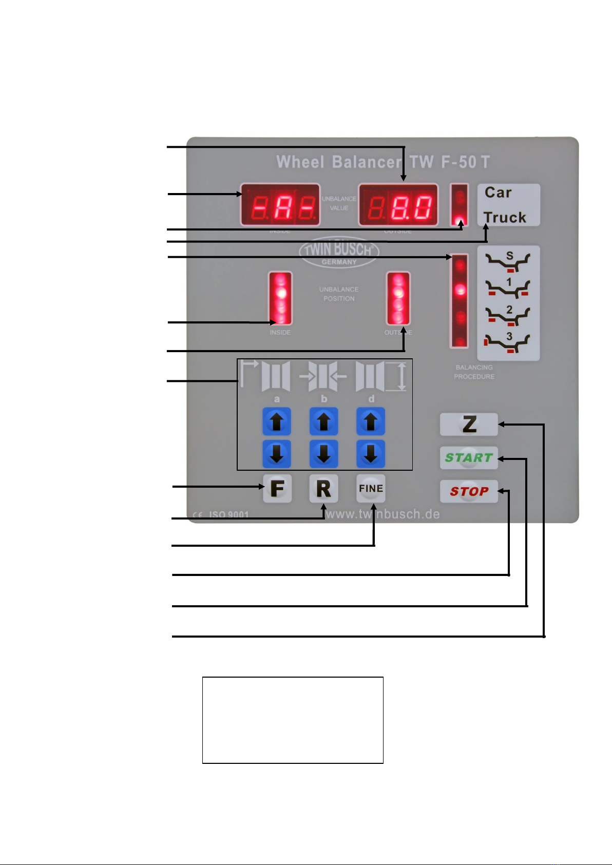
B. Introduction of panel..................................................................................... 9
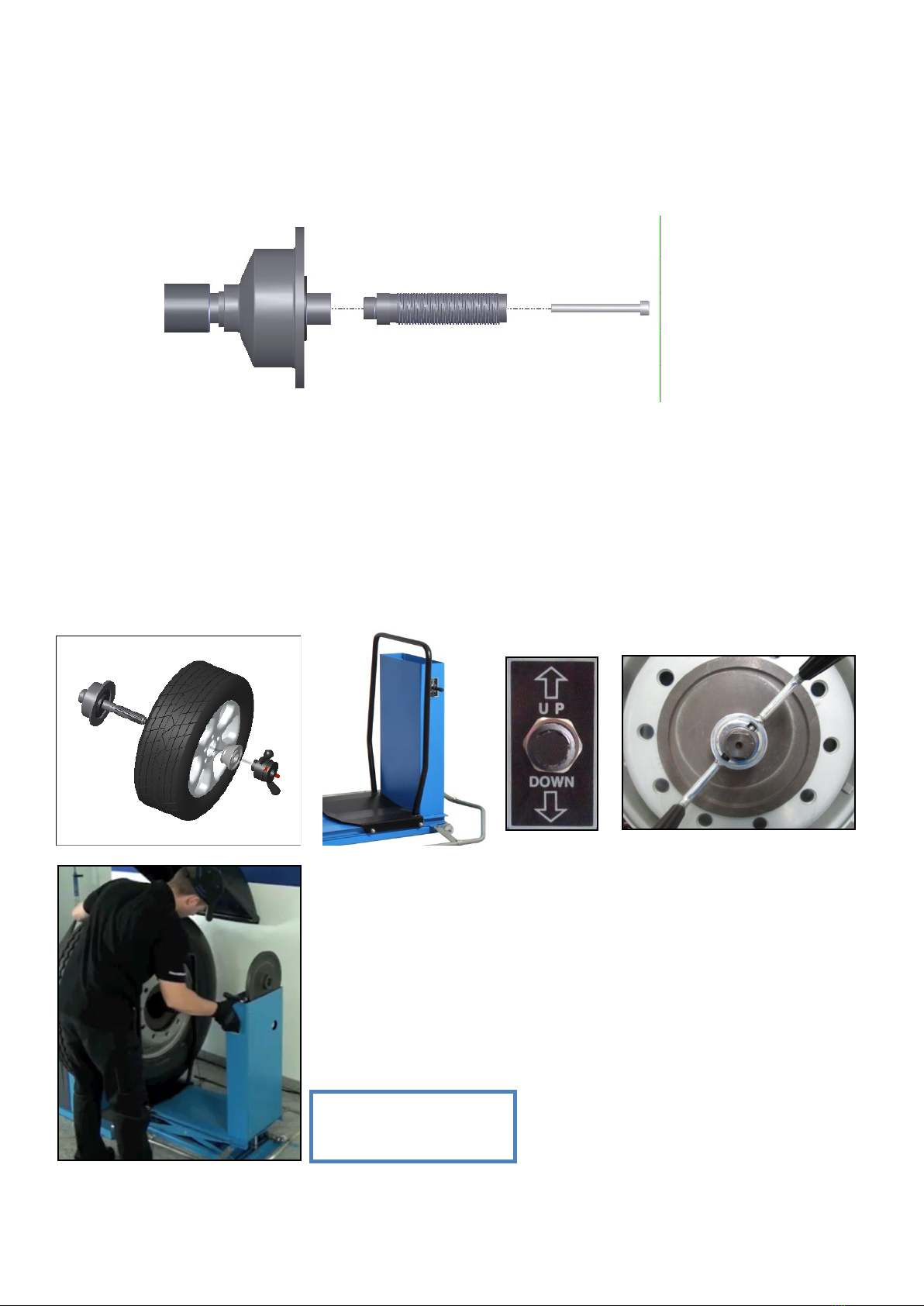
C. Mount the thread axle to the drive shaft / Fix wheel................................. 10
D. Putting through the power and number input............................................1 1
E. Size imput / Balancing examples ............................................................... 12
F. Precautions / Balancing experiences / Self correction.......................13- 15
4. Diagnosis of automatic trouble.......................................................................... 16
5. Options for mode of balancing .......................................................................... 17
6. Circiut diagram (220 V)....................................................................................... 18
7. Circiut diagram (400 V)....................................................................................... 19
8. Exploded drawings .................................................................................... 20 - 22
9. Spare part list ............................................................................................ 23 - 25
10. Space for notes ................................................................................................ 26
11. EG-declaration ................................................................................................. 27
12. Video link (QR code) ....................................................................................... 28

Technical changes for purposes of a technical advancement as well as deviation in colour, errors and printing mistakes are reserved. 4
1. Summary of the balancing machine
A. Brief introduction of appearance
1. Gauge
2. ON/OFF switch
3. Centering cones
4. Storage compartments
5. Display
6. Wheel cover
7. Quick release nut
8. Main shaft
9. Joystick (for pneumatic lift)
10. Wheel slide
11. Foot protection
12. Foot brake

Technical changes for purposes of a technical advancement as well as deviation in colour, errors and printing mistakes are reserved. 5
B. Performance and characteristics
● This machine adopts imported large-scale integrated circuit to make up the microcomputer system with high
intelligence and high stability. This machine is equipped with the counterweight optimization procedure.
● Main shaft of balancing adopts imported bearing for transmission, it is processed accurately.
It is wear-resisting and low noise.
● The most advanced motor driving system in 21st century in the world with extremely high stability.
● Test function of full-automatic dynamic balance and static balance.
● Functions to balance three kinds of aluminium alloy wheel rim.
● Balance precision is up to ±1g, balance takes at least 8 seconds each time.
● Functions of self correction and full automatic diagnosis.
● With pneumatical lifting device and international standard jig.
● With pedal positioning brake, stable positioning and convenient counterweight.

Technical changes for purposes of a technical advancement as well as deviation in colour, errors and printing mistakes are reserved. 6
C. Technical data table
Scope of application
Garage, transportation
company ,Department motorcade,
The professional service station of tyre
Width of steel rim
1,5”~20”
Diameter of steel rim
13”~24”
Maximum weight of wheel
150kg
Measurement time
8 seconds each time
Power supply
400 V
Noise level
<70dB
Net Weight
293 kg
2.Accessories accompanying machines.
A set of balancing machine and name of all accessories
1. one lead screw connecting with
main shaft
6.three cones,(scope is 45mm-190mm)
2.one plastic calliper
7.one nut
3.two bags of lead lump
8.one center wheel with bolt
4.one balance pincers
9.Matching machine outside shaft
5.Catalog,card of warranty,
certificate of conformity in one
copy.
Diameter of center holes × bolt holes(∮214×8 ∮221×8
∮221×10 ∮281×10 )

Technical changes for purposes of a technical advancement as well as deviation in colour, errors and printing mistakes are reserved. 7
Delivery contents
Please check all parts of delivery for completeness and damages in transit.
If something is missing or damaged, please contact the supplier directly.
Supplied accessories:
Overview
of cones
Diameter
Diameter
(inside)
Height
Weight
310 mm
150 mm
70 mm
8.5 kg
225 mm
150 mm
40 mm
3.5 kg
75-130 mm
50 mm / 44 mm
60 mm
1.0 kg
70-130 mm
40 mm
70 mm
3.0 kg
280 mm
40 mm
80 mm
7.0 kg
210-220 mm
40 mm
80 mm
5.5 kg
120-150 mm
40 mm
70 mm
5.0 kg

Technical changes for purposes of a technical advancement as well as deviation in colour, errors and printing mistakes are reserved. 8
3. Use of balancing machine
A. Attention before use
When moving the balancing machine you should only lift the machine chassis and n e v e r lift the machine by the shaft.
The Balancing machine and pneumatic lifting device must placed on level ground (should be fixed with expansion screw)
an unsteady machine could lead to false measurements. Leave enough space around the balancer for comfort of use.
● The power supply should meet local safety requirements and must be grounded
(earth connection is in rear of the machine).
● Balancing machine should not be placed in a damp environment, this could damage the machine.
● Before installing the leading spindle on the shaft, clean the main shaft and leading spindel level with alcohol or petrol
first, then connect the leading spindel to the main shaft and fasten w i t h a spanner.
● Before balancing any wheels, choose a suitable cone.
Then lock the wheel w i t h cone and nut (The inside of the wheel is facing the machine)
● Use the pneumatic lifting system for heavy wheels.
● The external air source connected to pneumatic lifting device must provide a minimum pressure of 0.8 bar

Technical changes for purposes of a technical advancement as well as deviation in colour, errors and printing mistakes are reserved. 9
B. Explanation of panel:
Key-combinations:
[R] + [START]: calibration
[R] + [F]: system check
[STOP] + [F]: Setting
Weight / outside
Weight / inside
Car / truck-display
Balancing program
Position display / inside
Position display / outside
Wheel size
a - Distance
b- W i d t h
c- Diameter
Change balancing mode
Reset
Exact gram display
S T O P
START
Change mode
car / truck

Technical changes for purposes of a technical advancement as well as deviation in colour, errors and printing mistakes are reserved. 10
C. Mount the threaded axle to the drive shaft
Use the allen screw to attach the threaded shaft to the drive shaft.
Fix the wheel
Check the wheel
Remove old weights and clean the wheel. Check tire pressure, according to
Correct prescribed pressure. Check if the wheel may have a radial run-out.
Mounting the wheel
Select the appropriate cone and tighten with the quick release nut.
Use the pneumatic lift
for heavy wheels.

Technical changes for purposes of a technical advancement as well as deviation in colour, errors and printing mistakes are reserved. 1 1
D. Putting through the power and number input
D.1 Putting through the power
Switching on power, the machine display board shows that it marks “001”, in the computer memory, it shows A-8.0
several seconds later which indicates that machine operation is normal.
Then input set wheel size, see following instruction about input method (note that balancing machine computer
automatically sets up dynamic balance each time when turning on computer)

Technical changes for purposes of a technical advancement as well as deviation in colour, errors and printing mistakes are reserved. 12
E.1 Size input
● For example testing luxurious wheel rim of Santana, please see picture on last
page , use ruler that this machine has to measure gap size between machine and
tyre: A=7.5cm
Press↑, number increases
Press↓, number decreases
● Use calliper that the machine has to measure ty width, see picture L=6.0 inch
Press↑, number increases
Press↓, number decreases
This size is caliber of tyre which needn’t to be measured, see tyre model “185/70
R13” d=13 inch Press↑, number increases
Press↓, number decreases
E.2 Some examples about balancing
● Press Start key, 8 seconds later, automatic brake shows as pictures:
140 is error value inside tyre
110 is error value outside tyre
● Rotate wheel to make inside indicator lamp be on and vertical over the main shaft,
strike 140g lead lump on wheel steel(may use pedal brake to assist making tyre
steady) as picture
● At this time inside indicator indicates 00, then rotate wheel to make outside
indicator lamp be on and vertical over the main shaft, take away 110g lead lump
from wheel steel as picture
● At this time outside indicator also indicates 00, balance is over, unload the tyre.If
you test tyre again, you needn’t switch off power.

Technical changes for purposes of a technical advancement as well as deviation in colour, errors and printing mistakes are reserved. 13
F.1 Precautions in the process of use and balancing experiences
!Attention: ·When power starts, push the wheel by hands to assist starting which will extend motor’s life. Due to balance
angle error, please find out by yourself when this machine rotates wheel to find balance point, pay attention which
direction is much more accurate w h en wheel turns inward or outward.
As the balance is over, unload the tyre, pay attention to handling with care , don’t strike the main shaft.
While assisting braking , by the time when the display board has data to show , then can step on the pedal brake at the
lower right corner of the machine , otherwise diminish the life-span of the machine.
F.2 Balancing experiences:
As indicated data is less than 50g, lead lump can be struck at the same time on both sides
When number is greater than 50g , producer proposes to balance one side after another, namely one side which
balance number is greater is balanced to reach “00” and then another side is balanced to reach " 00 ".
When there is still a small remaining part of lead lump after striking lead lump, it is because there is a error of lead lump
position,it can be solved through moving lead lump to direction where there is space.
After “00”-“00” occur, 5,6,7g will occor also by accident, it is thought to normal phenomenon.Precision of this machine is
5g namely it is zero below 4g. Allowed change scope of this machine is 3g, 7 g error will indicate by accident, it will not
affect balancing effect of this machine.
When appearing incorrectly or repeatedly strike but not reach 00, you can self correct the machine (please see the next
page for re-storation of standard process)
Comments: This experience is only for reference. Hope user can grasp machine performance skillfully for better use.

Technical changes for purposes of a technical advancement as well as deviation in colour, errors and printing mistakes are reserved. 14
F.2 Self correction
Self correction has been finished in the factory. If you use for many years and change part or doubt balance to be a big
error, you can self correct it again.( Choose one medium-sized tyre to install on main shaft, uneventy of steel rim on both
sides of wheel is relatively slight, only 13 inches and 14 inches). Input correct number of this tyre A, L , D.
Attention: incorrect input of size will lead to that machine can’t correctly
determine caliber so following measurement will have errors.
● Press R key, at the same time press START key in half a second ,display board
shows “CAL”-“CAL”, indicator lamps are all on. After indicator lamp goes out, then
loosen one’s grip.
●Press START key, the wheel rotated and brakes automatically, the display board
shows ND-CAL, show self correction is over.
●Press START key, the wheel rotated and brakes automatically, the display board
shows ND-CAL, showself correction is over.
●Press START key, stop in 8 seconds ,show the data, this step is to see directly if self
correction is successful and accurate.
● Well–balanced tyre by this achine shows data is “00”-“100” (±4g )after self correction.
100g lead lump is rightly under main shaft when outside indicator lamps are all on
( 4°error is allowed), this proves phase angle is correct.
Lights are all on when 100g lead lump is rightly under main shaft.
Two key elements to judge if self correction is accurate
1. Accurate number indication
2. Show that phase is right
(namely outside indicator lamps are all on and 100g lead lump is rightly under shaft).
Problems that occur after self correction:
●Number indicated is ok, but phase is inaccurate, deviation is very great.
Trouble: do not reduce after finishing striking the lead lump, usually the store device is damaged. Change it.
●Showing ERR (this machine screen shows Err. -8-)
A .Problems with computer board.
B .The circuit of sensor is broken.
●Number indicated has a big deviation, namely within 10g. (not affect using )

Technical changes for purposes of a technical advancement as well as deviation in colour, errors and printing mistakes are reserved. 15
A. Generally use lead lump of 100g inaccurately.
B. The edge outside wheel rim is irregular, can take down the lead lump and strike lead lump again on the opposite
side and make comparation through drawing 2 times average.
●Self correction cann’t be done because of different practices, fingers can slightly give a push.
Time difference between two fingers is half a second.
●Number indicated deviates a lot , changed number is still very big ,generally because the board damage of the
computer or the sensor is problematic.

Technical changes for purposes of a technical advancement as well as deviation in colour, errors and printing mistakes are reserved. 16
4. Diagnosis of automatic trouble
Code
Meaning
Cause
Solution
Err 1
Main shaft not rotating
1. Motor fault
2. Position sensor
3. Power board
4. CPU
5. Cable connection
1. Check motor
2. Check position sensor
3. Check power board
4. Change CPU
5. Check cable connection
Err 2
Revolutions less than 60
rpm
1. Position sensor
2. Wheel loose or too light
3. Motor
4. V-belt loose
5. CPU
1. Check position sensor
2. Tighten wheel
3. Check motor
4. Tension v-belt
5. Change CPU
Err 3
Wrong values
Too high imbalance
Calibration, check CPU
Err 4
Main shaft turning
wrong direction
1. Position sensor
2. CPU
1. check position sensor
2. Change CPU
Err 5
Protective cover
1. Cable connection
2. CPU
1. Check cable connection
2. Change CPU
Err 6
No sensor signal
1. Power board
2. CPU
1. Check power board
2. Change CPU
Err 7
Lost memory data
1. Wrong calibration
2. CPU
1. Calibration
2. Check CPU
Err 8
Calibration memory error
1. Forgot 100 gram weight
2. Power board
3. CPU
4. Pressure sensor
5. Cable connection
1. Calibrate 100 gram
2. Check power board
3. Change CPU
4. Check pressure sensor
5. Check cable connetion

Technical changes for purposes of a technical advancement as well as deviation in colour, errors and printing mistakes are reserved. 17
5. Options for mode of balancing
Balancing programs
Balancing program features
Choose following balancing programs depending to wheel material and rim design
pressing F-key several times. Active balancing program will be shown at control panel.
Dynamic balancing: standard, balancing weight fixed
for light alloy wheels at rim flange.
Dynamic balancing: standard, dynamic and static balancing, if
balancing weights could not be fixed at both sides of rims, f.e. at
motor cycle rims.
ALU 1 - balancing of light alloy wheels,
if balancing weight should be fixed under tyre seat.
ALU 2 - balancing of light alloy wheels,
if balancing weight should be hidden fixed.
ALU 3 - inner balancing weight with clip,
outer balancing weight hidden.
ATTENTION!
Power-on sets dynamic balancing.

Technical changes for purposes of a technical advancement as well as deviation in colour, errors and printing mistakes are reserved. 18
6. Circuit diagram (220 V)

Technical changes for purposes of a technical advancement as well as deviation in colour, errors and printing mistakes are reserved. 19
7. Circuit diagram (400 V)

Technical changes for purposes of a technical advancement as well as deviation in colour, errors and printing mistakes are reserved. 20
8. Exploded drawings
Table of contents
Other twin busch Wheel Balancer manuals
Popular Wheel Balancer manuals by other brands

Hoffman
Hoffman geodyna 6300-2 manual

HENNESSY INDUSTRIES
HENNESSY INDUSTRIES coats 1000 installation instructions

Rotary
Rotary R544PLUS Instruction, use and maintenance manual

ATH-Heinl
ATH-Heinl ATH W22 operating instructions

John Bean
John Bean VPI System IV Operation instructions

Hofmann
Hofmann Megaspin 800 Operating instructions manual