408-10004
6of 9
Rev B
A hashmark code (see Figure 2) should appear on
the bottom (side opposite the crimp indents) for
high temperature and heat-resistant terminals and
splices when crimped with the proper crimping
head.
6. MAINTENANCE AND INSPECTION
To avoid personal injury, disconnect air supply from
pneumatic tool before performing maintenance,
inspection, or repair procedures.
It is recommended that a maintenance and inspection
program be performed periodically to ensure
dependable and uniform terminations.
6.1. Daily Maintenance
It is recommended that each operator be responsible
for the following four steps of daily maintenance:
1. Remove dust, moisture, and outer contaminants
with a clean, soft brush or a lint-free cloth. Do NOT
use objects that could damage the heads.
2. Make sure that all pins, rings and other
components are in place and secure.
3. Make certain all surfaces are protected with a thin
coat of any good SAE 20 motor oil. Do NOT oil
excessively. Wipe excess grease from head,
particularly die closure areas.
4. When head assembly is not in use, store it in a
clean dry area.
6.2. Periodic Inspection
Regular inspections should be performed by quality-
control personnel. A record of scheduled inspections
should remain with the crimping heads or be supplied
to supervisory personnel responsible for the crimping
heads. Though recommendations call for at least one
inspection a month, the frequency should be based on
amount of use, working conditions, operator training
and skill, and your established company policies.
These inspections should include a visual inspection
(Paragraph 6.3) and a crimping chamber inspection
(Paragraph 6.5).
6.3. Visual Inspection
1. Make certain all components are in place. Inspect
for missing pins and retaining rings. If replacements
are necessary, refer to Figure 10.
2. Check all bearing surfaces for wear. Replace
worn parts.
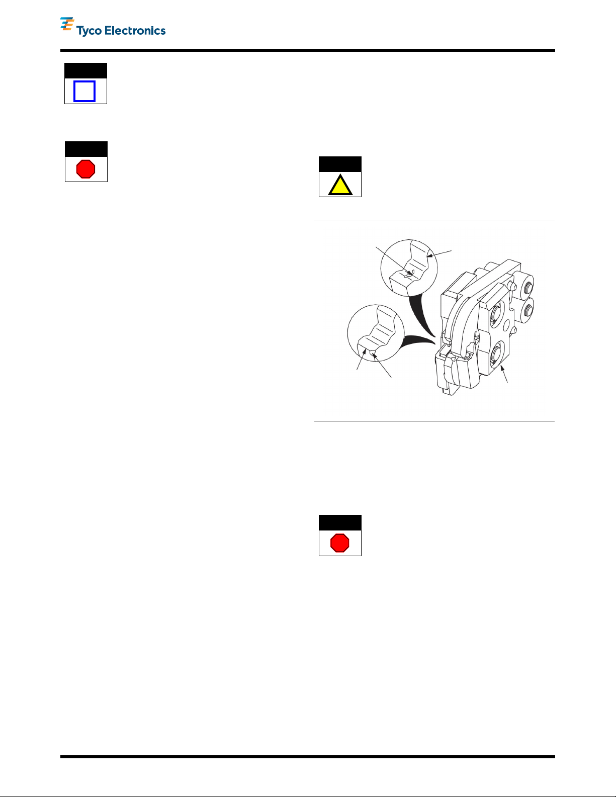
3. Inspect the crimp area for flattened, chipped, or
broken areas. See Figure 7. Replace worn or
damaged parts.
6.4. Lubrication
Lubricate all pins, pivot points, and bearing surfaces
with a high quality grease. Tyco recommends the use
of Molykotepaste, which is a commercially available
lubricant. Lubricate according to the following
schedule:
•Head used in daily production - lubricate daily
•Head used daily (occasional) - lubricate weekly
•Head used weekly - lubricate monthly
Wipe excess grease from crimping head,
particularly jaw closure areas. Grease transferred
from the jaw closure area onto certain terminations
may affect the electrical characteristics of an
application.
Figure 7
6.5. Gaging the Crimping Chamber
This inspection requires the use of plug gages
conforming to the dimensions shown in Figure 8. Tyco
Electronics does not manufacture or sell these gages.
Refer to 408-7424. Proceed as follows:
To avoid personal injury, disconnect air supply from
pneumatic tool and remove head from tool.
1. Remove oil and dirt from jaw bottoming surfaces,
jaw closure surfaces, and plug gage elements.
2. Set insulation adjustment pins in position 3. This
will allow access to the wire barrel crimping jaws
from the insulation crimp side of the head.
3. Close wire barrel crimping jaws until they are
bottomed, but not under pressure.
4. Align GO element with crimping chamber. Push
element straight into crimping chamber without
using force. The GO element must pass completely
through the chamber. See Figure 9, Detail A.
Pitted
Chipped Edge
Broken
Corner
Flattened
Area Crimping Head
1213850-[ ]
.
Trademark of Dow Corning Corporation