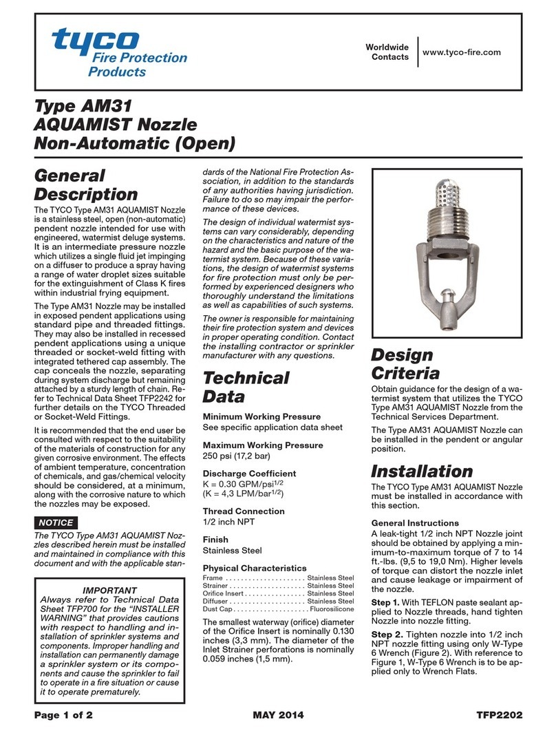
Tyco FSC 80 K-factor Flush Sprinkler User manual

General
Description
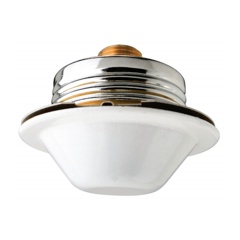
The TYCO Model FSC 80 K-factor Flush
Sprinkler Concrete Sprinklers are quick
response spray sprinklers designed for
use in areas such as ofces, hospitals,
churches, schools, apartments, and
hotels.
• For applications in poured concrete
ceiling/oor assemblies, a unique
Installation Cup is used to form the
recessed cavity into which the FSC
Sprinkler is installed
•
The ush design is made aestheti-
cally appealing by concealing the
deector and other operating parts
above the link assembly. The FSC
Sprinklers, with heat sensitive sol-
der type release elements, are rated
quick response sprinklers
NOTICE
The TYCO Model FSC 80 K-factor
Flush Sprinkler Concrete Sprinklers
described herein must be installed
and maintained in compliance with this
document and with the applicable stan-
dards CEA 4001 “Sprinkler Systems:
Planning and Installation” or EN12845
“Fixed Firefighting Systems - Automatic
Sprinkler Systems - Design, Installation
and Maintenance”, in addition to the
standards of any authorities having ju-
risdiction. Failure to do so may impair
the performance of these devices.
Tyco Fire Protection Products specifi-
cally disclaims any liability for damages
or injury (including death) arising out of
Physical Characteristics
Frame ..............................Brass
Deector Assembly . . . . . . . . . . . . . . . . . . Bronze
Sealing Assembly ........... Beryllium Nickel
with TEFLON
Link Assembly . . . . . . . . . . . . . . . . . . . . . Copper
Button .............................Brass
Deector Guide Pins . . . . . . . . . . . . . . . Stainless
Steel
Bridge...................... Stainless Steel
Levers...................... Stainless Steel
Plug ..............................Plastic
Escutcheon ......................... Steel
Installation Cup Assembly.............Plastic
Sprinkler Extension Thread.............Brass
Thread Adapter ......................Brass
Design
Criteria
General Criteria
The TYCO Model FSC 80 K-factor
Flush Sprinkler Concrete Sprinklers
are intended to be installed per CEA
4001 “Sprinkler Systems: Planning
and Installation” or EN12845 “Fixed
Fireghting Systems - Automatic
Sprinkler Systems - Design, Installation
and Maintenance” where Flush
Sprinklers are permitted. Only escutch-
eons shown in Figure 1 can be utilized
with the Model FSC 80 K-factor Flush
Sprinkler Concrete Sprinklers.
In all cases, CEA 4001 “Sprinkler
Systems: Planning and Installation” or
EN12845 “Fixed Fireghting Systems -
Automatic Sprinkler Systems - Design,
Installation and Maintenance” must be
followed to ensure proper installation.
The FSC Sprinklers can be used in nu-
merous scenarios including installation
in concrete ceilings/oors assemblies.
or caused by manipulation, dismantling,
or misuse of FSC Sprinklers or the use
or attempted use of the FSC Sprinklers
or any component thereof as an instru-
ment unrelated to its intended function
as a fire protection device.
The owner is responsible for maintain-
ing their fire protection system and de-
vices in proper operating condition.
The installing contractor or manufac-
turer should be contacted with any
questions.
Sprinkler
Identification
Number (SIN)
TY3200
Technical
Data
Approvals
VdS Approved
Flush Sprinkler Concrete is VdS
approved for installation per CEA
4001 “Sprinkler Systems: Planning
and Installation” or EN12845 “Fixed
Fireghting Systems - Automatic
Sprinkler Systems - Design, Installa-
tion and Maintenance”.
Maximum Working Pressure
12,1 bar (175 psi)
Discharge Coefficient
80,6 LPM/bar1/2 (K=5.6 GPM/psi1/2)
Temperature Rating
74°C (165°F)
Finishes
Sprinkler: White/Gray
Escutcheon: White/Gray
Model FSC 80 K-factor
Flush Sprinkler Concrete
Quick Response Standard Coverage
Page 1 of 6 OCTOBER 2012 TFP645
IMP O RTA NT
Always refer to Technical Data
Sheet TFP700 for the “INSTALLER
WARNING” that provides cautions
with respect to handling and
installation of sprinkler systems and
components. Improper handling and
installation can permanently damage
a sprinkler system or its components
and cause the sprinkler to fail to
operate in a fire situation or cause it
to operate prematurely.
Worldwide
Contacts
www.tyco-fire.com
*
*
*
SIDE VIEW
BOTTOM VIEW
OPERATED SIDE VIEW
(WITH ESCUTCHEON)
SPRINKLER
WRENCHING
NOTCHES
51 mm
(2")
35 mm DIA.
(1-3/8")
ESCUTCHEON
PLATE MOUNTING
SURFACE
G3/8"
DIN ISO 228
SPRINKLER
BODY
STYLE H
ESCUTCHEON
PLATE
LINK
ASSEMBLY
16 mm
(5/8")
3 mm
(1/8")
85 mm DIA.
(3-3/8")
DEFLECTOR
ASSEMBLY
IN OPERATED
POSITION
DEFLECTOR
GUIDE PIN
THREAD
SHOULDER
USE ONLY ORIENTATION DOT, LOCATED ON OUTER LINK
ADJACENT TO SPRINKLER WRENCHING NOTCH AND
PERPENDICULAR TO DEFLECTOR GUIDE PINS, AS VISUAL
INDICATION OF RELATIVE DEFLECTOR ORIENTATION AFTER
SPRINKLER INSTALLATION. POSITION OF INNER LINK TO
ORIENTATION DOT MAY VARY; DO NOT USE INNER LINK AS
REFERENCE TO VERIFY DEFLECTOR ORIENTATION AFTER
INSTALLATION OR DURING SUBSEQUENT INSPECTION.
OUTER
LINK
INNER
LINK
ORIENTATION
DOT
FIGURE 1
FLUSH SPRINKLER CONCRETE SPRINKLERS
DEFLECTOR
GUIDE PIN
WRENCHING
NOTCH
SOCKET
ACCEPTS
1/2" DRIVE
WRENCH FLAT
PARALLEL TO
GUIDE PINS
WHEN WRENCH
ENGAGES
SPRINKLER
(FLAT INDICATES
RELATIVE
ORIENTATION OF
DEFLECTOR AND
ORIENTATION DOT)
WRENCH
PRONGS
UNIQUELY
SPACED TO
ENGAGE
SPRINKLER
WRENCHING
NOTCHES
FIGURE 2
W-TYPE 25 SPRINKLER
INSTALLATION WRENCH
SOCKET
ACCEPTS
1/2" DRIVE
WRENCH SLOTS
ENGAGE INTERNAL
INSTALLATION
CUP RIBS
HEX
ACCEPTS
27 mm
WRENCH
FIGURE 3
W-TYPE 28 INSTALLATION CUP
REMOVAL WRENCH
TFP645
Page 2 of 6

85 mm DIA.
(3-3/8")
70 mm DIA.
(2-3/4")
ESCUTCHEON
PLATE
MODEL FSC
SPRINKLER
THREAD
EXTENSION
ADAPTER
FORMED
SPRINKLER
CAVITY IN
CONCRETE
STRUCTURE
EMBEDDED
SPRINKLER
FITTING
EMBEDDED
SYSTEM
PIPE
EXPOSED
CONCRETE
CEILING
6,4 mm
(1/4")
FIGURE 4
FLUSH SPRINKLER CONCRETE INSTALLATION
EXPOSED CONCRETE CEILING
15 mm
(19/32")
MAXIMUM
85 mm DIA.
(3-3/8")
70 mm DIA.
(2-3/4")
ESCUTCHEON
PLATE
CEILING
FINISH
MODEL FSC
SPRINKLER
THREAD
EXTENSION
ADAPTER
FORMED
SPRINKLER
CAVITY IN
CONCRETE
STRUCTURE
EMBEDDED
SPRINKLER
FITTING
EMBEDDED
SYSTEM
PIPE
6,4 mm
(1/4")
FIGURE 5
FLUSH SPRINKLER CONCRETE INSTALLATION
FINISHED CONCRETE CEILING
TFP645
Page 3 of 6

Installation
For poured concrete ceiling/oor ap-
plications, the TYCO Model FSC 80
K-factor Flush Sprinkler Concrete
Sprinklers must be installed in accor-
dance with this section.
Step 1. Center Cup Insert at sprinkler
location and fasten to concrete form
with either nails or screws.
Step 1 Step 3
Step 3. Place Installation Cup
Assembly with Sprinkler Fitting over
Cup Insert. Ensure Installation Cup
Assembly snaps into place and is ush
against concrete form.
Step 2. Ensure O-Ring is properly tted
beneath threads on neck of Installation
Cup. Screw Installation Cup Assembly
into Sprinkler Fitting.
Step 2
Step 5
Step 5. After required pressure test
has been successfully performed, pour
concrete ceiling/oor. Ensure concrete
is distributed evenly around Installation
Cup Assembly, Sprinkler Fitting, and
Pipe.
CAUTION
Use extreme caution when distributing
the concrete around the Pipe so as not
to nick or split the Pipe. Failure to do so
may result in equipment damage and/
or system failure.
Step 4. Connect Pipe to Fitting per
manufacturer’s recommendations.
Repeat steps 1 through 4 for remain-
ing sprinkler locations. Once all Pipes
have been connected, perform system
pressure test.
Step 4 Step 6
Step 6. Once the concrete has cured,
remove the concrete forms. The Cup
Inserts will be removed along with the
concrete form.
TFP645
Page 4 of 6

Step 11
Step 11. Engage FSC Sprinkler using
W-Type 25 Wrench (Figure 7), and then
screw into Adapter. Hand-tighten FSC
Sprinkler into Adapter until Escutcheon
is ush with ceiling surface and sprin-
kler is positioned in intended orientation
(Refer to Figures 1 and 2 for orientation
details.).
Note: The W-Type 25 Wrench will en-
gage the FSC Sprinkler in only one way.
When the sprinkler is engaged by the
wrench, the at on the wrench is par-
allel to the deector guide pins and at
installation, indicates the relative sprin-
kler deector orientation.
Step 10
Step 10. Assemble Escutcheon onto
FSC Sprinkler as shown. Apply sealant
to external threads of Thread Extension.
NOTICE
Ensure sealant avoids contact with
guide pins and internal waterway of
Thread Extension. Failure to do so may
result in equipment failure.
Step 12
Step 12. Ensure sprinkler is securely in
place then remove W-Type 25 Wrench
from sprinkler.
Repeat steps 7 through 12 to install re-
maining sprinklers.
Step 9
Step 9. Apply sealant to external
threads on FSC Sprinkler Inlet. With
hex end of Thread Extension oriented
toward the sprinkler inlet, screw onto
sprinkler threads until hex end is ush
with sprinkler thread shoulder.
NOTICE
Ensure sealant avoids contact with
guide pins and internal waterway of
Sprinkler Inlet. Failure to do so may re-
sult in equipment failure.
Step 7
Step 7. Insert W-Type 28 Wrench
(Figure 3) into Installation Cup cav-
ity ensuring it properly engages inter-
nal ribs and is fully seated. Using a 27
mm hex wrench or a 1/2 inch drive, un-
screw Installation Cup Assembly from
Sprinkler Fitting and remove from ceil-
ing cavity. Ensure O-Ring, as part of the
Installation Cup Assembly, has been
removed.
Note: Ceiling nish or coating should
be applied before proceeding on to
sprinkler installation in remaining steps.
Step 8
Step 8. Apply sealant (not included
with sprinkler kit) to external threads of
Adapter. Screw Adapter into Sprinkler
Fitting until Adapter shoulder is ush
with face of tting.
TFP645
Page 5 of 6

Care and
Maintenance
The TYCO Model FSC 80 K-factor Flush
Sprinkler Concrete Sprinklers must be
maintained and serviced in accordance
with this section:
Service inspections should be made
on a regular basis to detect possible
damage or alterations to the sprinkler
and escutcheon. Inspections should in-
clude making certain that the escutch-
eon is held fast to the mounting sur-
face. Damaged or altered sprinklers
are to be replaced immediately to avoid
personal injury and to prevent use for
causing personal injury, as well as to
maintain the sprinkler system in an op-
erative condition.
Before closing a re protection system
main control valve for maintenance
work on the re protection system that
it controls, obtain permission to shut
down the affected re protection sys-
tem from the proper authorities and no-
tify all personnel who may be affected
by this action.
Sprinklers which are found to be leak-
ing or exhibiting visible signs of corro-
sion must be replaced.
Automatic sprinklers must never be
painted, plated, coated, or other-
wise altered after leaving the factory.
Modied sprinklers must be replaced.
Sprinklers that have been exposed to
corrosive products of combustion, but
have not operated, should be replaced
if they cannot be completely cleaned
by wiping the sprinkler with a cloth or
by brushing it with a soft bristle brush.
Care must be exercised to avoid dam-
age to the sprinklers - before, during,
and after installation. Sprinklers dam-
aged by dropping, striking, wrench
twist/slippage, or the like, must be
replaced. Also, replace any sprinkler
that has a cracked bulb or that has lost
liquid from its bulb. (Ref. Installation
Section.)
Frequent visual inspections are recom-
mended to be initially performed for
sprinklers installed in potentially corro-
sive atmospheres to verify the integrity
of the materials of construction as they
may be affected by the corrosive con-
ditions present for a given installation.
The owner is responsible for the in-
spection, testing, and maintenance of
their re protection system and devices
in compliance with this document, as
well as with the applicable standards
of the approval agency and standards
of any other authority having jurisdic-
tion. Contact the installing contractor
or sprinkler manufacturer regarding any
questions.
Sprinklers are recommended to be in-
spected, tested, and maintained by a
qualied Inspection Service in accor-
dance with local requirements and/or
national codes.
Ordering
Procedure
Contact your local distributor for avail-
ability. When placing an order, indicate
the full product description and Part
Number (P/N).
Sprinkler Assemblies
Specify: Model FSC 80 K-factor Flush
Sprinkler Concrete Sprinklers Quick
Response Standard Coverage, 74°C
(165°F), with Thread Extension and
Adapter, with (specify) nish and P/N
(specify).
White ....................P/N 50-313-4-165
Gray .....................P/N 50-313-9 -165
Concrete Installation Kit (Incl. Installation Cup,
Cup Insert, and O-Ring) .....P/N 91-313-1-110
Separately Ordered
Parts for Sprinkler
Flush Sprinkler Concrete Sprinkler:
White ....................P/N 51-313-4-165
Gray .....................P/N 51-313-9-165
Extension Thread...........P/N 91-313-1-008
Adapter ..................P/N 91-313-1-007
Separately Ordered
Style H Escutcheons
(85 mm Diameter)
White ....................P/N 56-313-4-010
Gray .....................P/N 56-313-9-010
Separately Ordered
Parts Installation Kit
Installation Cup w/O-Ring ....P/N 91-313-1-100
Cup Insert.................P/N 91-313-1-004
Separately Ordered
Sprinkler Wrench
Specify: W-Type 25 Installation Wrench,
P/N 56-314-1-001.
Specify: W-Type 28 Installation Cup
Removal Tool, P/N 56-000-4-301.
Copyright © 2012 Tyco Fire Products, LP. All rights reserved.
TEFLON is trademark of The DuPont Corporation.
GLOBAL HEADQUARTERS | 1400 Pennbrook Parkway, Lansdale, PA 19446 | Telephone +1-215-362-0700
TFP645
Page 6 of 6
Table of contents
Other Tyco Firefighting Equipment manuals
Popular Firefighting Equipment manuals by other brands

PAB
PAB FIRE 05 user manual

Task Force Tips
Task Force Tips VORTEX 2 ER manual

Task Force Tips
Task Force Tips STANDARD INSTRUCTIONS FOR SAFE OPERATION AND MAINTENANCE

Eaton
Eaton EFCV2Z Installation and operation manual

TFT
TFT Extend-A-Gun XG18 manual

Security Brands
Security Brands S-1515 User & installation manual

Janus
Janus FM-200 Sv Series Operation & service manual

Amerex
Amerex A384T Installation, operating & servicing instructions

Global Fire Equipment
Global Fire Equipment ZEOS-AS-S quick start guide

FireWare
FireWare FireSales user manual

Global Fire Equipment
Global Fire Equipment GFE-PA-VOX-A manual

Chubb
Chubb PEFS F3 Maintenance manual