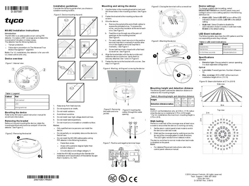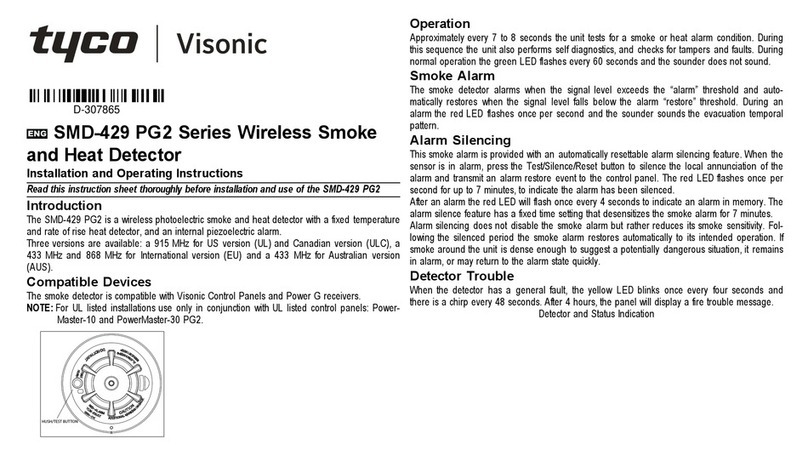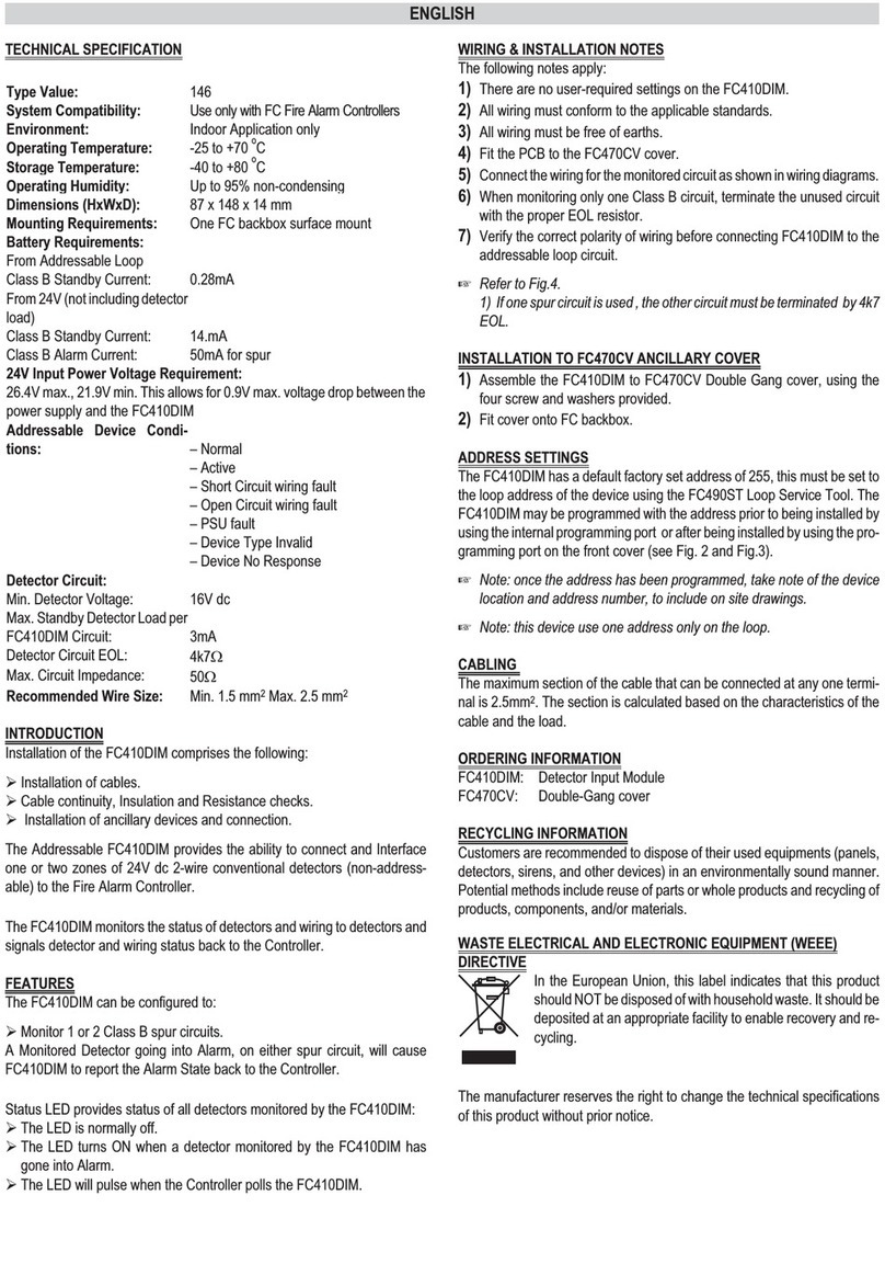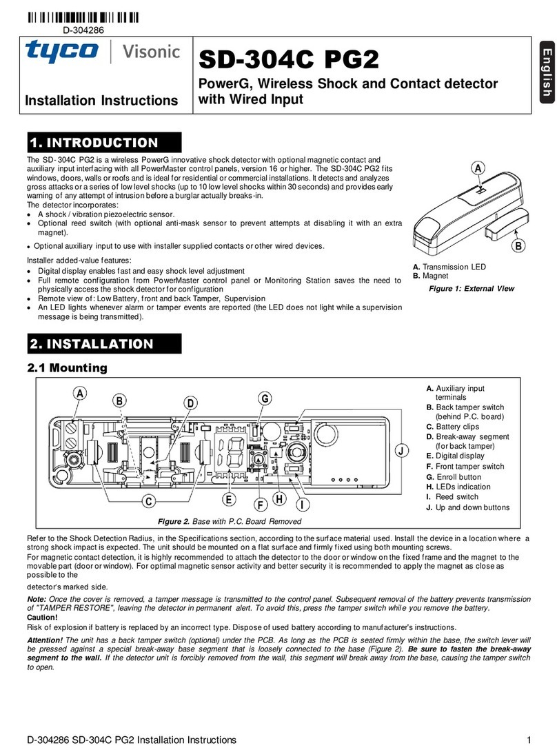
Tyco 614 Series
Collective Smoke and CO
Fire Detectors
I N F O R M A T I O N S H E E T
DESCRIPTION
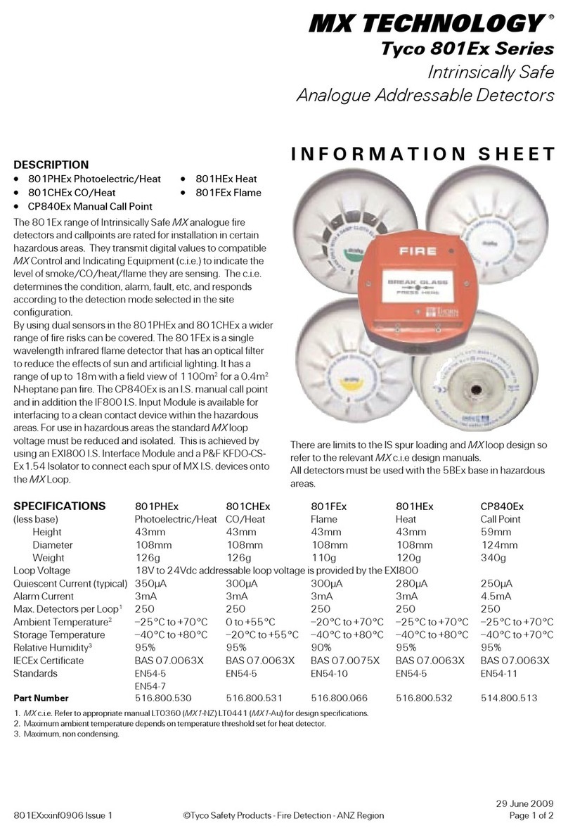
The Tyco 614 series of low profile fire detectors consists of:
• 614CH combined Carbon Monoxide (CO) and Heat detector
Using both CO and Heat sensors in combination enables an increase in
the sensitivity of the CO sensor when a rapid increase in temperature is
present (heat enhancement), making the 614CH suitable for detecting
both slow smouldering and fast flaming fires. The heat sensor also acts
as an independant rate-of-rise and fixed temperature detector Class A1R,
conforming to AS 7240.5-2004. The 614CH is well suited to applications
where heat detection alone is insufficient but smoke detectors are
vulnerable to nuisance alarms.
• 614P Photoelectric (Scattered Light) smoke detector
The 614P is listed as conforming to AS 7240.7:2004 and is well suited
to detecting visible smoke produced by smouldering fires including
overheated electrical cabling.
• 614I Ionisation smoke detector
The 614I Ionisation smoke detector is listed as conforming to
AS 7240.7:2004. It reacts to visible and invisible fire aerosols enabling
early detection of flaming fires.
The 614T Type A, B, C and D Heat detectors supplement the Tyco 614
series for heat only applications - refer separate information sheet. The 614
series detectors are compatible with Vigilant F3200, MX4428 and Simplex
4100U c.i.e. They may be used as service replacements for the Minerva 614
series detectors both on these and the obsolete F08 and F4000 panels.
INSTALLATION
The base should be fixed so that the park plunger faces toward the door
or trafficable area, to suit the 614T, should it be used. This ensures the
detector LED will be visible from the direction of entry, in accordance with
AS 1670.1-2004. However, the 614P/I/CH LED is visible through 360°
and can be oriented differently to suit the application. For effective detection
of fast flaming fires in sleeping areas, 614CH detectors should be spaced as
per heat detector requirements. Refer to the 5B base information sheet for
more details. The Tyco 614 detectors mount onto the base with a clockwise
rotational motion. Rotating the detector anticlockwise past an indent to the
park position disconnects the detector from the circuit whilst still retaining
it in the base. Depressing the plunger at the side of the base allows the
detector to be rotated back into its operating position.
TESTING
The 614CH is tested using the X330 in-situ tester with CO detector test
gas, part no. 517.001.262. The heat sensor can be tested in-situ using
the X461 test unit, in sleeping areas and where detection is engineered to
depend on the heat sensor. The 614P and 614I smoke detectors can be
tested in-situ using the X330 Test Tool with X500 Test Smoke.
MAINTENANCE
The Tyco 614 series detectors should be maintained in accordance with the
relevant section of AS 1851 (Australia) or NZS 4512:2003 (New Zealand).
Additionally, although the 614CH has an expected life in excess of 10
years, in order for the 614CH to provide the intended level of fire detection,
the detector should be checked for calibration 5 years after installation (or
5 years after re-installation following service) or within 7 years of the date
of manufacture. Wormald Detector Clean & Calibration Wollongong are
equipped and competent to check the calibration of 614CH detectors.
Environmental conditions of temperature and humidity outside the specified
range for more than momentary excursions may detrimentally affect the
service life or operation of the 614CH.
LOCKING DEVICE
A detector locking device is moulded into the 5B base.
This must be detached and inserted into the locking
aperture if required, prior to the selected detector being
installed. The detector may then be removed only by
inserting an unlocking tool (a Ø3 x 22mm long rod) into
the hole on the detector cover to depress the locking
device.
19 February 2008
Tyco614Inf0802 Issue 6 Tyco Safety Products - Australasia Page 1 of 2
SPECIFICATIONS
614CH 614I 614P
10 to 33Vdc 12 to 33Vdc 10 to 33Vdc
Quiescent Current
70µA 60µA 60µA
Alarm State Current1
5mA to 85mA
Alarm State Voltage 2
4V to 7.6V
Ext. Powered Load 3
50mA at 28Vdc (max.)
Ambient Temp
(min)
4
0°C -20°C -20°C
Ambient Temp
(max)
+50°C +70°C +70°C
Rel. Humidity
(min)
5
15% 10% 10%
Rel. Humidity
(max)
5
90% 95% 95%
Alarm Indicator Colour
Red
Remote Indicator
Tyco E500 Mk2 series
Dimensions (mm)
54 x 127 (H x dia)
Sensitivity
38ppm, A1R 0.32 MIC X 4%Obs/m
CSIRO ActivFire Listed
afp1718 afp1716 afp1715
Part Numbers
516.600.304 516.600.305 516.600.301
5B Base
517.050.017
In-situ Smoke Tester
517.001.255
In-situ Heat Tester
X461
Test Gas
517.001.262 X500 X500
Specifications are typical unless stated otherwise.
1. Must be externally limited. Minimum current for required LED visibility is 5mA.
Maximum current 85mA at 55°C. 2. Minimum voltage with remote indicator
shorted @ 5mA. Max @ 85mA without remote indicator connected. 3. Remote
indicator output can control external load from +24V, eg. sounder. 4. Storage
temp for 614CH -20°C to +55°C without exposure to icing or condensation.
5. Humidity must be non-condensing.

