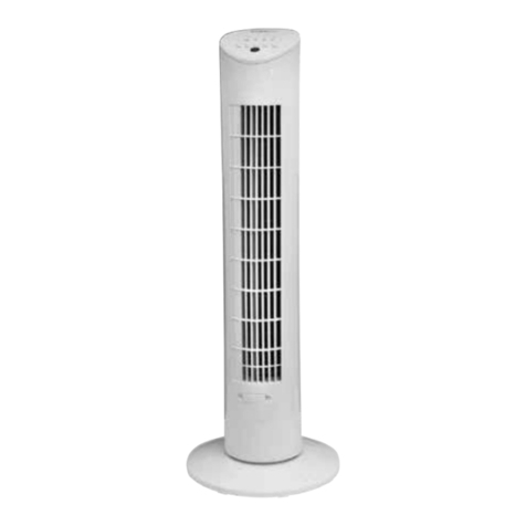
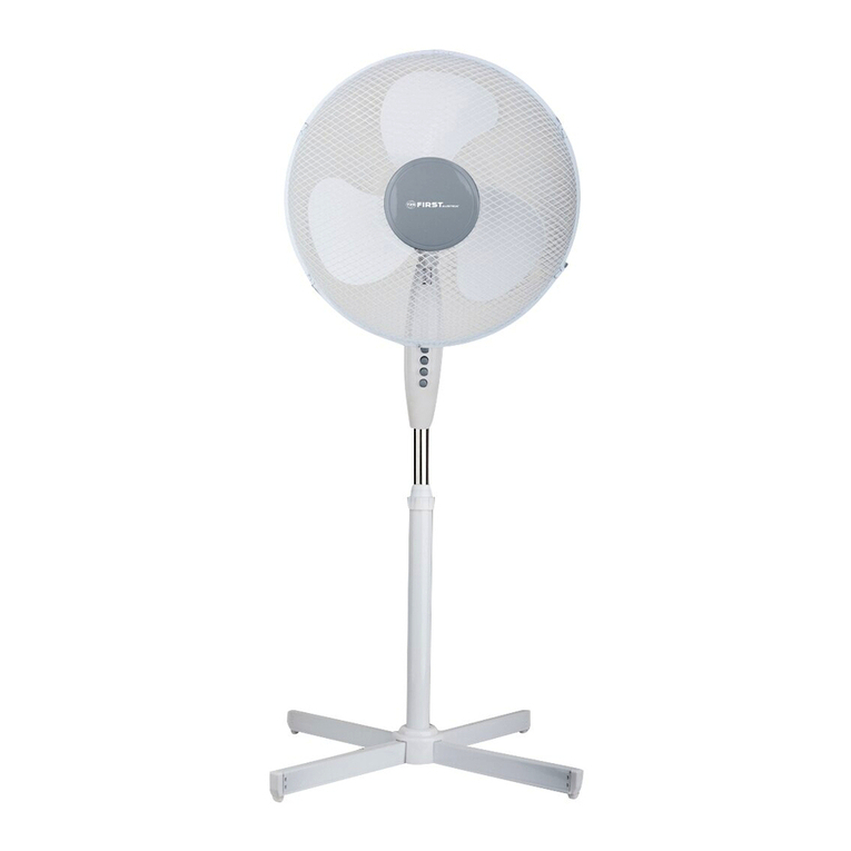
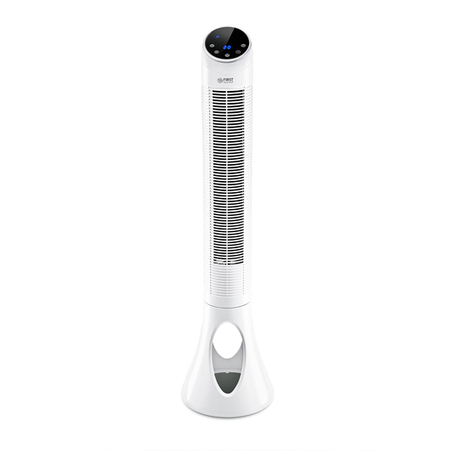
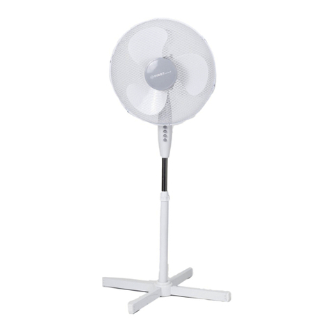
TZS First AUSTRIA FA-5551 User manual

24 25
FA-5562/FA-5551/FA-55523•
FA-55502•
80 :FA-5551/FA-555090 •
•
50240-220 •
45 :FA-5562 & FA-555240 :FA-555120 :FA-5550 •
•
•
•
50240-220 •
•
•
•
•
•
•
•
•
•
•
•
•
•
•
•
40 •
•
•
•
•
DESK FAN
INSTRUCTION MANUAL
TISCHVENTILATOR
BEDIENUNGSANLEITUNG
WENTYLATOR NASTOLNY
INSTRUKCJA OBSŁUGI
НАСТОЛЬНЫЙ
ВЕНТИЛЯТОР
PRAVILA QKSPLUATACII
VENTILATOR DE MASĂ
MANUAL DE UTILIZARE
STALINIS VENTILIATORIUS
NAUDOJIMO INSTRUKCIJA
STONI VENTILATOR
UPUTSTVO ZA UPOTREBU
GALDA VENTILATORS
LIETOŠANAS PAMĀCĪBA
НАСТОЛЕН ВЕНТИЛАТОР
УПЪТВАНЕ ЗА
ИЗПОЛЗВАНЕ
НАСТІЛЬНИЙ ВЕНТИЛЯТОР
ІНСТРУКЦІЯ З
ЕКСПЛУАТАЦІЇ
VENTILATEUR DE TABLE
NOTICE D’UTILISATION
FA-5550, FA-5551
FA-5552, FA-5562
ENGLISH.................. PAGE 2
DEUTSCH ............... SEITE 4
POLSKI............... STRONA 6
RUSSKIJ................. STR. 8
ROMANESTE ..... PAGINA 10
LIETUVIU K. .................. P. 1 2
SCG/CRO/B.i.H. STRANA 14
LATVIAN.................... LPP. 16
........... STR. 18
........
FRANÇAIS ............. PAGE 22
24.........................
:)1
11
12
13
14
15
6
7
8
9
10
1
2
3
4
5
)2 1
•
•
6 •
)3 2
•
•
)4 3
•
•
•
FA-5551/FA-55525 4
•
•
1
2
31 3
)6

INSTRUCTION MANUAL
Thank you for purchasing this high quality Fan. Our fans have been carefully designed and constructed to
meet the highest standards of performance, quality and safety. Please read the instructions carefully to ensure
satisfactory and trouble free use.
YOUR FAN FEATURES
• 3 Speed Control for FA-5551/FA-5552/FA-5562
• 2 Speed Control for FA-5550
• Oscillation over an Angle of 90° (FA-5550/FA-5551: 80°)
• Protective Grille
• 220-240V • 50Hz
• Max. Power:
• 5550: 20W
• 5551: 40W
• 5552: 45W
• 5562: 45W
IMPORTANT SAFEGUARDS
When using electrical appliances, basic safety precautions should always be followed, including the following:
• Read all instructions carefully and save these instruction manual for reference.
• To protect against electric shock, do not immerse cord, plug or fan into water or any other liquid.
• Do not use appliance for other than intended use.
• Use the appliance only on the voltage specified on its rating plate (220-240V/50Hz).
• Unplug from outlet when not in use and before cleaning.
• Do not pull the connection cord over sharp edges and never jam it.
• Do not pull the plug out of the socket by pulling the connection cord.
• Do not use outdoors.
• Do not use an extension cord, unless the cord has been checked and tested by your electrical authority or
a qualified technician.
• Close supervision is necessary when any appliance is used by or near children.
• Always use your appliance on a suitabel level and dry platform.
• Avoid using an appliance where it can fall or be pushed into water. Never reach for an appliance after it has
fallen into water. Switch off at the mains power point und unplug immediately.
• Never attempt to insert any object through the grille when the fan is operating.
• Always disconnect fan when moving from one location to another.
• Do not operate any appliance with a damaged cord or plug or after the appliance malfunctions, or has been
damaged in any manner.
• Do not cover the grille.
• If the fan is to be stored for an extended period of time or not used regularly, replace it in the original
packaging (or similar) and store it in a dry and clean place. Before using again, check if the unit is clean and
dry and if the fan blades rotates freely.
• This appliance is not intended for use by persons (including children) with reduced physical, sensory or
mental capabilities, or lack of experience and knowledge, unless they have been given supervision or
instruction concerning use of the appliance by a person responsible for their safety.
• Children should be supervised to ensure that they do not play with the appliance.
DESCRIPTION OF PARTS picture 1)
ASSEMBLY INSTRUCTIONS
Please assemble correctly by the following orders when using:
picture 2)
• Screw the blade fastening screw out in clockwise direction and screw the net fastening screw out in anti-
clockwise direction.
• Fix the rear guard onto the three pillars of the motor front shell.
• Screw the net fastening screw (6) tightly in clockwise direction.
picture 3)
• Put the fan blade onto the electrical axle centre and the axle centre bolt must be pressed to the end of the
concave notch at the back of the fan blade. They must be tallied completely.
• Screw the screw into the electrical axle centre in anti-clockwise direction and then fix it.
picture 4)
• Put the hook of the front guard ring on the top of rear net.
• Put the rear net into the front guard ring to make them tally completely.
• Tighten the fastening screw of the lower of the front guard ring.
picture 5) for FA-5551/FA-5552
• Put the stand base into the main body, it must be pressed to the end of the main bady. They must to tallied
completely.
• Screw the screw into the main body.
OPERATING INSTRUCTIONS
1. To make the fan head oscillating push down the oscillating knob. To stop the fan head oscillating pull the
oscillating knob.
2. To adjust the airflow upwards, simply loosen the swivel adjustment knob and move to desired angle then
firmly tighten the swivel adjustment knob.
3. Speed is controlled by pressing the piano keys. (1 = slow, 3 = fast)
ELECTRICAL PRINCIPLE DIAGRAM
See fig. 6
Environment friendly disposal
You can help protect the environment! Please remember to respect the local regulations: hand in the non-
working electrical equipments to an appropriate waste disposal center.
3
ENGLISH
2
ENGLISH
1. Front guard
2. Guard Clops Screw
3. Guards Clops
4. Blade Fastening screw
5. Fan Blade
6. Guard Fastening screw
7. Rear Guard
8. Electrical axle centre
9. Front shell
10. Rear shell
11. Oscillate control knob
12. Control switch
13. Main Body
14. Standing Base
15. Adjustable Angle Knob

TEILEBESCHREIBUNG (Bild 1)
ZUSAMMENBAU
Bitte befolgen Sie beim Zusammenbau die folgenden Instruktionen.
1. ANBRINGEN DES HINTEREN SCHUTZGITTERS (Bild 2):
• Nehmen Sie die Flügelschraube ab, indem Sie diese mit dem Uhrzeigersinn drehen. Drehen Sie die
Schutzgitterbefestigungsschraube entgegen dem Uhrzeigersinn ab.
• Setzen Sie das rückwärtige Schutzgitter auf die drei Stifte des Motorvorderteils auf.
• Schrauben Sie die Schutzgitterbefestigungsschraube im Uhrzeigersinn fest.
2. BEFESTIGUNG DES VENTILATORFLÜGELS (Bild 3):
• Setzen Sie den Flügel in der Mitte der Achse an.Danach schieben Sie ihn soweit nach hinten bis die beiden
Ausnehmungen des Flügels richtig in die beiden Zapfen auf der Achse eingerastet sind.
• Danach befestigen Sie den Flügel indem Sie die Flügelbefestigungsschraube entgegen dem Uhrzeiger-
sinn drehen.
3. BEFESTIGUNG DES VORDEREN SCHUTZGITTERS (Bild 4):
• Setzen Sie das Schutzgitter so auf, dass der Haken des Rings sich oben auf dem hinteren Gitter befindet.
• Verbinden Sie den hinteren Teil mit dem Ring des Vorderteils bis er komplett eingerastet ist.
• Befestigen Sie die Schraube auf der Unterseite des Rings.
4. MONTAGE STANDFUSS (Bild 5) für FA-5551/FA-5552:
• Setzen Sie den Standfuß in das Gerätegehäuse ein, drücken Sie ihn fest an.
• Schrauben Sie den Standfuß am Gerätegehäuse an.
BEDIENUNGSANLEITUNG
1. Der Rotierknopf muß gedrückt sein, wenn der Ventilatorkopf in eine Schwenkbewegung versetzt werden soll.
Wenn der Ventilator nur in eine Richtung blasen soll, ziehen Sie den Rotierknopf nach oben.
2. Lösen Sie die Verschraubung um den Ventilatorkopf zu beugen oder zu heben, stellen Sie ihn auf die
gewünschte Höhe ein und drehen Sie die Verschraubung wieder zu fest.
3. Um die Geschwindigkeit einzustellen, drücken Sie die Taste für die gewünschte Geschwindigkeitsstufe.
(1 = langsam, 3 = schnell)
ELEKTRISCHES DIAGRAMM
Siehe Abb. 6
Power = Ein/Aus
Control switch = Schalter
Red = Rot
Blue = Blau
White = Weiß
Motor = Motor
Fuse = Sicherung
Capacitor = Kondensator
Entsorgung
Helfen Sie mit beim Umweltschutz!
Entsorgen Sie Elektroaltgeräte nicht mit dem Hausmüll. Geben Sie dieses Gerät an einer Sammelstelle für
Elektroaltgeräte ab.
5
DEUTSCH
4
DEUTSCH
BEDIENUNGSANLEITUNG
Danke für den Kauf eines qualitativ hochwertigen Produktes. Unsere Ventilatoren würden sorgfältig gestaltet
und konstruiert, um den höchsten Ansprüchen an Qualität und Sicherheit zu entsprechen.
Zur gefahrlosen Verwendung dieses Gerätes, lesen Sie bitte diese Bedienungsanleitung sorgfältig durch.
SPEZIFIKATIONEN
• 3 Geschwindigkeitsstufen für FA-5551/FA-5552/FA-5562
• 2 Geschwindigkeitsstufen für FA-5550
• Schutzgrill
• Schwenkkopf 90° (FA-5550/FA-5551: 80°)
• 220-240V • 50Hz
• Max. Leistung:
• 5550: 20W
• 5551: 40W
• 5552: 45W
• 5562: 45W
WICHTIGE SICHERHEITSHINWEISE
Bei der Verwendung elektrischer Geräte beachten Sie bitte immer die folgenden grundlegenden
Sicherheitshinweise:
• Lesen Sie die Bedienungsanleitung sorgfältig, und heben Sie diese gut auf.
• Um einen elektrischen Schlag zu vermeiden, tauchen Sie niemals Kabel, Stecker oder Ihr Gerät in Wasser
oder andere Flüssigkeiten.
• Verwenden Sie das Gerät nur für den vorgesehenen Zweck.
• Schließen Sie das Gerät nur an eine passende Steckdose mit gleicher Netzspannung, wie der, auf dem
Typenschild an der Geräteunterseite angegebenen, an. (220-240V/50Hz)
• Ziehen Sie den Stecker aus der Steckdose, wenn das Gerät nicht in Gebrauch ist und bevor Sie es reinigen.
• Ziehen Sie das Stromkabel niemals über scharfe Kanten und klemmen Sie es nicht ein.
• Ziehen Sie niemals den Stecker aus der Steckdose, indem Sie am Kabel ziehen.
• Verwenden Sie das Gerät nicht im Freien.
• Verwenden Sie kein Verlängerungskabel, das nicht durch Fachpersonal geprüft worden ist.
• Passen Sie besonders auf, wenn das Gerät von Kindern oder in Ihrer Nähe verwendet wird.
• Verwenden Sie das Gerät immer auf einer ebenen und trockenen Fläche.
• Verwenden Sie das Gerät nicht in der Nähe von Wasser, wo es hineinfallen oder hineingestoßen werden
könnte.Greifen Sie nicht nach dem Gerät wenn es ins Wasser gefallen ist. Schalten Sie den FI-Schalter aus
und ziehen Sie dann sofort den Stecker aus der Steckdose.
• Stecken Sie niemals Gegenstände durch den Schutzgrill während der Ventilator in Betrieb ist.
• Ziehen Sie immer den Stecker aus der Steckdose bevor Sie das Gerät an einem anderen Platz verwenden.
• Verwenden Sie das Gerät nicht, wenn das Kabel oder der Stecker beschädigt ist, es nicht vorschriftsgemäß
funktioniert, oder wenn es in irgendeiner Weise beschädigt worden ist.
• Decken Sie den Schutzgrill nie zu.
• Wenn Sie den Ventilator nur selten oder länger nicht benutzen, bewahren Sie das Gerät in der
Originalverpackung und an einem trockenen, sauberen Platz auf. Wenn Sie das Gerät dann wieder heraus-
nehmen, vergewissern Sie sich, dass das Gerät sauber und trocken ist und sich das Flügelrad frei dreht.
•Dieses Gerät ist nicht für die Benutzung durch Personen (einschließlich Kinder) mit verminderten physi-
schen, sensorischen und geistigen Fähigkeiten oder unzureichender Erfahrung und Kenntnis geeignet,
es sei denn, es wurden Anleitungen betreffs der Benutzung des Geräts durch eine verantwortliche
Aufsichtsperson erteilt.
•Kinder müssen beaufsichtigt werden, damit sie nicht mit dem Gerät spielen.
1. Vorderes Schutzgitter
2. Schutzgitterhalteschraube
3. Schutzgitterhalterung
4. Flügelbefestigungsschraube
5. Ventilatorflügel
6. Schutzgitterbefestigungs-
schraube
7. hinteres Schutzgitter
8. elektrische Wellenmitte
9. Gehäusevorderfront
10. Gehäuserückteil
11. Knopf für Oszillierfunktion
12. Kontrollschalter
13. Gerätegehäuse
14. Standfuß
15. Verschraubung (für Beugen
und Heben)

7
POLSKI
INSTRUKCJA OBSŁUGI
DANE TECHNICZNE
FA-5551/FA-5552/FA-5562
FA-5550
• Siatka ochronna
• 220-240V • 50Hz
• Moc max:
• 5550: 20W
• 5551: 40W
• 5552: 45W
• 5562: 45W
INFORMACJE DOTYCZĄCE BEZPIECZEŃSTWA
•
funkcjonuje poprawnie.
•
•
OPIS CZĘŚCI (obraz 1)
6
POLSKI
MONTAŻ
1. MOCOWANIE TYLNEJ KRATKI OCHRONNEJ (obraz 2):
wskazówek zegara.
(obraz 3):
wskazówek zegara.
3. MOCOWANIE PRZEDNIEJ KRATKI OCHRONNEJ (obraz 4):
(obraz 5) dla FA-5551/FA-5552:
INSTRUKCJA OBSŁUGI
DIAGRAM UKŁADU ELEKTRYCZNEGO
Patrz il. 6
Power = Zasilanie
Red = Czerwony
Blue = Niebieski
Motor = Silnik
Fuse = Bezpiecznik
Capacitor = Kondensator
Utylizacja przyjazna środowisku
1. Kratka ochronna przednia
3. Zamocowanie kratki ochronnej
7. Kratka ochronna tylna
9. Front przedni obudowy
11. Przycisk do funkcji oscylacyjnej
14. Podstawa
schylania i podnoszenia)

OPISANIE SBORHASTEJ (video 1)
SBORKA
Pri sborke sledujte, poøalujsta, sleduüwim instrukciäm:
1. USTANOVKA ZADNEJ ZAWITNOJ RE∏ETKI (video 2):
• Snimite lopastnyj vint, povernuv ego po hasovoj strelke. Povernite bolt zakrepleniä
re‚etki po hasovoj strelke.
• Nasadite zadnüü zawitnuü re‚etku na tri ‚tyrä perednej hasti korpusa.
• Zaventite do predela bolt zakrepleniä re‚etki.
2. ZAKREPLENIE LOPASTEJ (video 3):
• Nasadite lopasti na seredinu osi i dvigajte ix nazad, poka vyemki na lopastäx ne vstanut na
capfy osi i zafiksiruütsä.
• Zatem zakrepite lopasti povernuv bolt zakrepleniä lopastej protiv hasovoj strelki.
3. USTANOVKA PEREDNEJ ZAWITNOJ RE∏ETKI (video 4):
• Nasadite re‚etku tak, htoby krühok naxodilsä poverx kol´ca zadnej re‚etki.
• Soedinite zadnüü hast´ s kol´com perednej hasti tak, htoby krühok zafiksirovalsä.
• Zakrepite bolt v niønej hasti kol´ca.
4. (video 5) dlä FA-5551/FA-5552:
•
•
INSTRUKCIÄ PO QKSPLUATACII
1. Dlä togo, htoby ventilätor vrawalsä naΩmite na ruhku vibracii. Dlä ostanovki vibracii
vytäniteruhkuvibraciinaruΩu.
2. Dlä togo, htoby napravitß struoe voqduxa vverx, prosto osvobodite Ruhku Nastrojki Vraweniä
i povernite ee v Ωelaemom napravlenii, pod pravilßnyj ugol i qatem qakrepite Ruhku
Nastrojki Vraweniä.
3. SkorostßreguliruetsänaΩatiemknopkinaperekloehatele.
ОСНОВНАЯ ЭЛЕКТРИЧЕСКАЯ СХЕМА
Power =
Control switch =
Red =
Blue =
White =
Motor =
Fuse =
Capacitor =
СРОК ГОДНОСТИ НЕ ОГРАНИЧЕН.
Экологическая утилизация
9
RUSSKIJ
8
RUSSKIJ
PRAVILA QKSPLUATACII
PREDISLOVIE
BlagodarimVasqapokupkuztogovysokokahestvennogoVentilätora.Na˚iventilätorytwatelßno
splanirovany i skonstruirovany dlä proävleniä xarakteristik, podxodäwix vysohaj˚im
trebovaniämdejstviä,kahestvaibeqopasnosti.Prohtite,poΩalujsta,vnimatelßnoztiinstrukcii
dlä obespeheniä udovletvoritelßnogo i besproblemnogo polßqovaniä.
XARAKTERISTIKI VAÍEGO VENTILÄTORA
• Trex - skorostnoj regulätor. dlä FA-5551/FA-5552/FA-5562
• Dvux - skorostnoj regulätor. dlä FA-5550
•
• Oscilläciä pod uglom v 90 gradusov. (FA-5550/FA-5551: 80°)
• 220-240V • 50Gc
• Mownost´:
• 5550: 20Vt
• 5551: 40Vt
• 5552: 45Vt
• 5562: 45Vt
PERVYM DELOM - BEZOPASNOST`
1. Vsegda soblœdajte osnovnye pravila beqopasnosti.
2. Prohtitevnimatelßnoinstrukcii.VsegdaderΩiteixpodrukojdläkonsulßtacii.
3. Dläpredotvraweniäzlektriheskogo˚okanikogdaneopuskajtenikakojzlektriheskijpribor
vvoduililœbuœdruguœΩidkostß.
4. Polßqujtesß zlektropriborami sugubo dlä prednaqnahennoj celi.
5. PolßqujtesßzlektropriboromtolßkonanapräΩenii,ukaqannomnafabrihnomwitke.
6. Vsegdavyklœhitepribordotogo,htootklœhaeteegootseti.Otklœhajteotseti,priderΩivaä
˚tekker,anedergaäqa˚nur.
7. Vyklœhite pribor i vyberite iq roqetki, kogda pribor ne naxoditsä v polßqovanii, ili pered
histkoj.
8. Nekrutitesilovoj˚nur,takkakztomoΩetprivestikoslableniœipovreΩdeniœiqoläcii.
9. Ne polßqujtesß priborom na ulice.
10. Ne polßqujtesß udlinitelem, kotoryj ne byl proveren specialistom.
11.KogdapribornaxoditsävupotrebleniivokruΩeniidetejiliprestarelyxlœdej,neobxodim
nadqor.
12. Vsegda polßqujtesß priborom na podxodäwem urovne i suxoj poverxnosti.
13.Neupotrebläjtepriborvmestax,gdeonmoΩetupastßilipopastßvvodu.Nikogdanepytajtesß
vybratß pribor iq vody, esli on upal v nee. Snahala otklœhite pitanie toka, i nemedlenno
vyklœhite ego iq seti.
14.Ne dopustite, htoby ˚nur valälsä takim obraqom, hto on stanet pomexoj. Ne dopuskajte
soprikosnoveniä˚nuraslœbojgorähejpoverxnostßœ.
15.Nikogda ne pytajtesß prosunutß kakoj - libo predmet hereq re˚etku vo vremä raboty
ventilätora.
16.NeobxodimovsegdaotklœhitßventilätorpriperedviΩeniiegosmestanamesto.
17.Nepokryvajtere˚etki.
18. Esli Vy ne sobiraetesß polßqovatßsä priborom v tehenie dlitelßnogo vremeni ili ne
polßquetesß priborom regulärno, pomestite ego v originalßnuœ upakovku (ili poxoΩuœ)
i xranite ego v suxom i histom meste. Kogda Vy ego qanovo ispolßquete posle dolgogo
neupotrebleniä,proverßte,htopriborhistyjisuxojihtonoΩipriborasvobodnovrawaœtsä.
19.Esli silovoj ˚nur povreΩden, neobxodimo qamenitß ego u proiqvoditelä ili v punkte po
obsluΩivaniœilivkrajnemsluhaeukvallificirovannogopersonaladläiqbeΩaniäopasnosti.
1. Perednää zawitnaä re‚etka
2. Bolt derøatelä re‚etki
3. Derøatel´ re‚etki
4. Bolt zakrepleniä lopastej
5. Ventiläcionnye lopasti
6. Bolt zakrepleniä re‚etki
7. Zadnää zawitnaä re‚etka
8.
9. Perednää hast´ korpusa
10. Zadnää hast´ korpusa
11. Knopka funkcii vraweniä
12. Vyklühatel´
13.
14.
15. Knopka vibracii
INSTRUCŢIUNI DE ASAMBLARE
imaginea 2)
orar.
imaginea 3)
imaginea 4)
imaginea 5) (FA-5551/FA-5552)
INSTRUCŢIUNI DE UTILIZARE
SCHEMĂ ELECTRICĂ
V. fig. 6:
Power = Alimentare
Blue = Albastru
White = Alb
Motor = Motor
Capacitor = Condensator
Eliminare ecologică
11
ROMANESTE
10
ROMANESTE
MANUAL DE UTILIZARE
CARACTERISTICILE VENTILATORULUI DVS.
• 220-240V • 50Hz
• Putere:
• 5550: 20W
• 5551: 40W
• 5552: 45W
• 5562: 45W
INSTRUCŢIUNI DE SIGURANŢĂ IMPORTANTE
lichide.
DESCRIEREA COMPONENTELOR imaginea 1)
5. Elice ventilator
8. Ax central electric
15. Buton de reglare unghi

13
LIETUVIU K.
12
LIETUVIU K.
SURINKIMAS
4. STOVO SURINKIMAS (5 pav.) (FA-5551/FA-5552 modeliuose):
NAUDOJIMO INSTRUKCIJA
greitai)
PAGRINDINĖ ELEKTROS GRANDINĖS SCHEMA
Power = Maitinimas
Control switch = Valdymo jungiklis
Red = Raudona
White = Balta
Motor = Variklis
Fuse = Saugiklis
Capacitor = Kondensatorius
Aplinkai saugus išmetimas
NAUDOJIMO INSTRUKCIJA
TECHNINIAI DUOMENYS
• Palenkiama galva 90° (FA-5550/FA-5551: 80°)
• 220-240V • 50Hz
• Maks. galia:
• 5550: 20W
• 5551: 40W
• 5552: 45W
• 5562: 45W
SVARBŪS SAUGOS REIKALAVIMAI
• Nenaudokite prietaiso atviroje vietoje.
DALIŲ APRAŠYMAS (1 pav.)
8. Elektrinis veleno centras
11. Svyravimo funkcijos mygtukas
12. Kontrolinis jungiklis
13. Pagrindinis korpusas
14. Pastatomas pagrindas
15. Pasukimo reguliavimo

SKLAPANJE
1. POSTAVLJANJE ZADNJE ZAŠTITNE REŠETKE (slika 2):
2. PRIVRŠIVANJE PROPELERA VENTILATORA (slika 3):
• Postavite propelera na sredinu osovine. Zatim ga gurnite toliko ka nazad sve dok oba ispusta na propeleru
3. PRIVRŠIVANJE PREDNJE ZAŠTITNE REŠETKE (slika 4):
(slika 5) za FA-5551/FA-5552
• Savite postolje u glavno telo, ono mora da se potisne do kraja u glavno telo. Oni moraju u potpunosti da se
• Navrnite zavrtanj u glavno telo.
UPUTSTVO ZA UPOTREBU
duva samo u jednom pravcu, izvucite dugme za rotiranje na gore.
ELEKTRIČNA PRINCIPIJELNA ŠEMA
Vidite sliku 6
Power = Napajanje
Control switch =
Red = Crveno
Blue = Plavo
White = Belo
Motor = Motor
Fuse =
Capacitor = Kondenzator
Ekološko odlaganje otpada
centar za odlaganje otpada.
15
SCG/CRO/B.I.H.
UPUTSTVO ZA UPOTREBU
uputstvo.
TEHNIČKE OSOBINE
• 3 stepena brzine za FA-5551/FA-5552/FA-5562
• 2 stepena brzine za FA-5550
• Rotiranje 90° (FA-5550/FA-5551: 80°)
• 220-240V • 50Hz
• Maks. snaga:
• 5550: 20W
• 5551: 40W
• 5552: 45W
• 5562: 45W
VAŽNA SIGURNOSNA UPUTSTVA
•
•
OPIS DELOVA (slika 1)
14
SCG/CRO/B.I.H.
propelera
5. Propeler ventilatora
11. Dugme za funkciju osciliranja
13. Glavno telo
14. Postolje

IERĪCES UZSTATĪŠANA
1.
•
•
2.
•
3.
•
•
LIETOŠANAS PAMĀCĪBA
ELEKTRISKĀ PRINCIPA SHĒMA
Power = Jauda
Control switch =
Red = Sarkans
Blue = Zils
White = Balts
Motor = Motors
Fuse =
Capacitor = Kondensators
Videi draudzīga atbrīvošanās no ierīces
17
LATVIAN
LIETOŠANAS PAMĀCĪBA
SPECIFIKĀCIJAS:
FA-5551/FA-5552/FA-5562
FA-5550
• Aizsargsiets
• 220-240V • 50Hz
• 5550: 20W
• 5551: 40W
• 5552: 45W
• 5562: 45W
SVARĪGI DROŠĪBAS NOTEIKUMI
no kontaktligzdas.
•
•
DETAĻU APRAKSTS
16
LATVIAN
2. Aizspiednis
3.
skava
5. Propellers
11. Pacelöanas un nolaiöanas poga
13. Korpuss
14. Pamatne

УПЪТВАНЕ ЗА ИЗПОЛЗВАНЕ
ХАРАКТЕРИСТИКИ НА ВЕНТИЛАТОРА
FA-5551/FA-5552/FA-5562
FA-5550
• 220-240V • 50Hz
• 5550: 20W
• 5551: 40W
• 5552: 45W
• 5562: 45W
ВАЖНИ УКАЗАНИЯ ЗА БЕЗОПАСНОСТ
•
•
ОПИСАНИЕ НА ЧАСТИТЕ
МОНТАЖ:
:
:
:
FA-5551/FA-5552:
УПЪТВАНЕ ЗА ОБСЛУЖВАНЕ:
ЕЛЕКТРИЧЕСКА СХЕМА
Power =
Control switch =
Red =
Blue =
White =
Motor =
Fuse =
Capacitor =
Съобразено с околната среда изхвърляне
БЪΛГАРСКИ
БЪΛГАРСКИ
18 19

20 21
УКРАЇНСЬКА
УКРАЇНСЬКА
ІНСТРУКЦІЯ З ЕКСПЛУАТАЦІЇ
ХАРАКТЕРИСТИКИ ВЕНТИЛЯТОРА
ВАЖЛИВІ ЗАСТЕРЕЖЕННЯ
ОПИС ДЕТАЛЕЙ
ІНСТРУКЦІЯ ЗІ ЗБИРАННЯ
ІНСТРУКЦІЯ ЩОДО ФУНКЦІЙ
ПРИНЦИПІАЛЬНА ЕЛЕКТРИЧНА СХЕМА
ТЕРМІН ПРИДАТНОСТІ: НЕ ОБМЕЖЕНИЙ.
Безпечна утилізація

22 23
FA-5550
FA-5551/5552
3
4
5
N
L
2
1
0
FA-5551/5552 FA-5550
2
FA-5562
6
1
3
4
5
6
7
15
8
10 12
11
14
1
FRANÇAIS
FRANÇAIS
MODE D’EMPLOI
SPÉCIFICATIONS
• 3 niveaux de vitesse pour FA-5551/FA-5552/FA-5562
• 2 niveaux de vitesse pour FA-5550
• Grille de protection
• Tête pivotante 90° (FA-5550/FA-5551: 80°)
• 220-240V • 50Hz
• Puissance max. :
• 5550: 20W
• 5551: 40W
• 5552: 45W
• 5562: 45W
INDICATIONS DE SÉCURITÉ IMPORTANTES
• Ne couvrez jamais la grille de protection.
vous que celui-ci est propre et sec et que le rouet tourne librement.
mises sous la garde d‘une personne pouvant les surveiller.
DESCRIPTION DES PIÈCES ill. 1)
MONTAGE
Veuillez suivre lors du montage les instructions suivantes.
illustration 2)
la grille de protection dans le sens contraire.
• Placez la grille de protection arrière sur les trois tiges de la partie avant du moteur.
illustration 3)
montre.
illustration 4)
illustration 5) pour FA-5551/FA-5552
• Serrez les vis dans le corps principal.
OPERATING INSTRUCTIONS
pivotant. Si vous voulez que le ventilateur souffle seulement dans une direction, tirez le bouton rotatif vers le
haut.
la fixation.
SCHÉMA DE BRANCHEMENT ÉLECTRIQUE
Voir fig. 6
Power = Alimentation
Control switch = Interrupteur de commande
Red = Rouge
Blue = Bleu
White = Blanc
Motor = Moteur
Fuse = Fusible
Capacitor = Condensateur
Mise au rebut dans le respect de l‘environnement
1. Grille de protection avant
2. Vis de fixation de la grille de
protection
3. Attache grille de protection
4. Vis de serrage ailette
5. Ailette
6. Vis de serrage grille de
protection
7. Grille de protection arrière
11. Bouton pour fonction oscillante
13. Corps principal
14. Base d‘appui

McGrp.Ru
Сайт техники и электроники
Наш сайт McGrp.Ru при этом не является просто хранилищем
инструк ий по эксплуата ии, это живое сообщество людей. Они общаются
на форуме, задают вопросы о способах и особенностях использования техники.
На все вопросы очень быстро находятся ответы от таких же посетителей сайта,
экспертов или администраторов. Вопрос можно задать как на форуме, так и
в спе иальной форме на страни е, где описывается интересующая вас техника.
This manual suits for next models
4
Table of contents
Languages:
Other TZS First AUSTRIA Fan manuals

TZS First AUSTRIA
TZS First AUSTRIA FA-5560-3 User manual

TZS First AUSTRIA
TZS First AUSTRIA FA-5560-4 User manual

TZS First AUSTRIA
TZS First AUSTRIA FA-5564-1 User manual

TZS First AUSTRIA
TZS First AUSTRIA FA-5553-2 User manual

TZS First AUSTRIA
TZS First AUSTRIA FA-5560-1 User manual

TZS First AUSTRIA
TZS First AUSTRIA FA-5560-2 User manual

TZS First AUSTRIA
TZS First AUSTRIA FA-5550 User manual

TZS First AUSTRIA
TZS First AUSTRIA FA-5553-1 User manual

TZS First AUSTRIA
TZS First AUSTRIA FA-5550 User manual