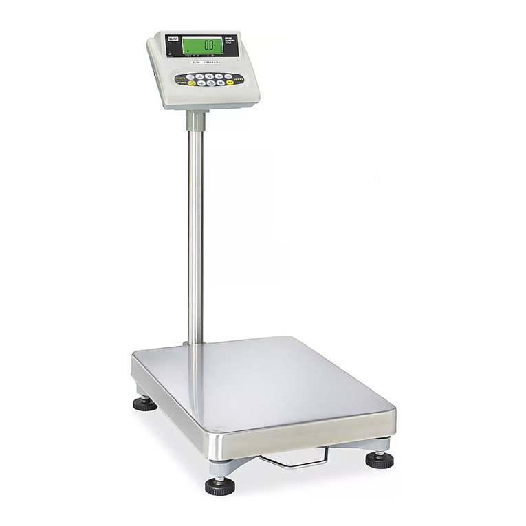
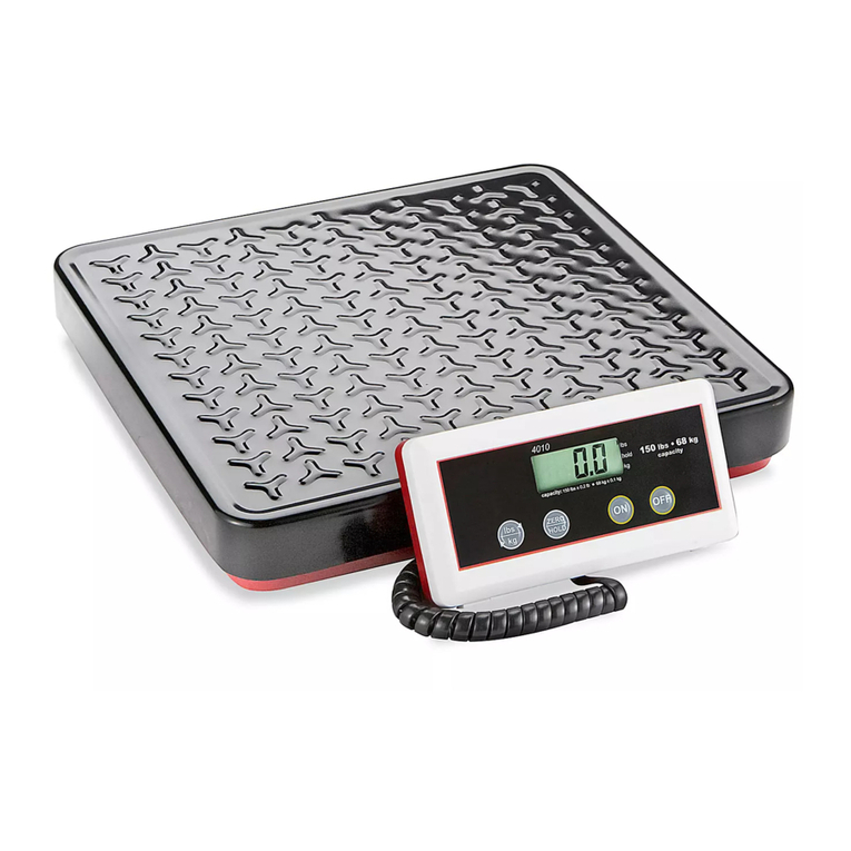
U-Line H-2289 User manual

PAGE 1 OF 8 1214 IH-2289
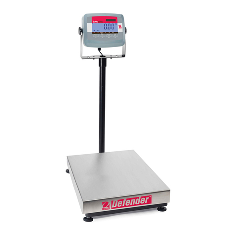
πH-2289, H-2290, H-2291
OHaus DefenDer™
5000 DIGITaL scaLe
1-800-295-5510
uline.com
OVERVIEW OF CONTROLS
CONTROL PANEL
#DESCRIPTION
1 Under LED
2Accept LED
3Over LED
4 Capacity Label Window
5 TARE Menu Button
6 FUNCTION Mode Button
7 PRINT Units Button
8 ON/ZERO Off Button
BUTTON
PRIMARY FUNCTION
(Short Press)
ON/ZERO
Turns the indicator ON
If indicator is ON, sets
zero.
PRINT
Sends the current value to
the COM port if AUTOPRINT
is set to off.
FUNCTION
Initiates an application mode.
Temporarily displays the active
mode's reference data.
In Weigh mode, temporarily
displays 10x expanded resolution
TARE
Performs a tare
operation.
SECONDARY FUNCTION
(Long Press)
OFF
Turns the indicator off.
UNITS
Changes the weighing
unit.
MODE
Allows changing the application
mode.
Press and hold allows scrolling
through modes.
MENU
Enter the User Menu.
MENU FUNCTION
(Short Press)
YES
Accepts the current
setting on the display.
NO
Advances to the next
menu or menu item.
Rejects the current setting
on the display and
advances to the next
available setting.
Increments the value.
BACK
Moves back to previous menu
item.
Decrements the value.
EXIT
Exits the User Menu.
Aborts the calibration
in progress.
CONTROL FUNCTIONS
CONTROL PANEL PARTS
On/Zero
Off
Yes
Print
Units
No
Function
Mode
Back
Tare
Menu
Exit
lb
Print
Units
No
Function
Mode
Back
Tare
Menu
Exit
On/Zero
Off
Yes
Under Over
Accept
123
4
5
6
7
8

PAGE 2 OF 8 1214 IH-2289
OPERATION
TURNING INDICATOR ON/OFF
1. To turn the Indicator on, press the
ON/ZERO OFF button. The Indicator
performs a display test followed by a
series of informational displays and
then enters the active weighing mode.
2. To turn the Indicator off, press and hold the ON/ZERO
OFF button until OFF is displayed.
MENU NAVIGATION
TO ENTER THE MENU MODE
1. Press the TARE MENU button until
MENU is displayed. When the button
is released, the Legal for Trade status
is displayed, followed by the first
menu.
YES Allows entry into the displayed menu.
Views menu item setting.
Accepts the displayed setting.
NO/BACK Skips by the displayed menu.
Rejects the displayed setting and
advances to the next available item.
EXIT Exits from menu directly to the current
application.
2. For menu items with numeric settings
such as Capacity, the current setting
is displayed with all digits flashing.
Press the NO button to begin editing.
3. The first digit is displayed flashing.
4. Press the NO button to increment
the digit or press the YES button to
accept the digit and move to the
next digit.
5. Repeat this process for all digits.
6. Press the YES button when the last
digit has been set.
7. The new setting is displayed with all
digits flashing. Press the YES button
to accept the setting or press the NO
button to resume editing.
8. This method also applies to setting Check Weigh
under and over targets.
9. For End menu items, pressing the YES button
advances to the next menu, while pressing the NO
button returns to the top of the current menu.
CALIBRATION MENU
Three calibration processes are available:
Zero Calibration, Span Calibration and Linearity
Calibration. (See Figure 1)
1. Make sure that appropriate calibration masses are
available before beginning calibration.
2. Make sure that the scale base is level and stable
during the entire calibration process.
3. Calibration is unavailable with LFT set to ON.
4. Allow the Indicator to warm up for approximately 5
minutes after stabilizing to room temperature.
5. To abort calibration, press the EXIT button anytime
during the calibration process.
6. When any selection within the GMP menu is enabled,
calibration results are automatically printed.
ZERO CALIBRATION
Zero calibration uses one calibration point. The zero
calibration point is established with no weight on
the scale. Use this calibration method to adjust for a
different pre-load without affecting the span or linearity
calibration.
1. When ZErO is displayed, press the YES
button to initiate Zero Calibration.
2. The display flashes 0 and the
calibration unit. Press the YES button
to establish the zero point.
3. The display shows --C-- while the
zero point is established.
MENU
000000
000000
100000
100000
100000
Figure 1
Zero Perform
Span Perform
Linearity Perform
Cal Test Perform
Geographic
Adjustment Set 00... Set 12... Set 31
End Calibration Exit CALIBRATE menu
ZErO
--C --
0 kg
CALIBRATION VALUES
MODEL # SPAN CALIBRATION
POINTS (kg.)
LINEARITY CALIBRATION
POINTS (kg.)
H-2289 50 25, 50
H-2290 100 50, 100
H-2291 250 125, 250

PAGE 3 OF 8 1214 IH-2289
OPERATION CONTINUED
4. When zero calibration is completed,
the display shows dONE.
5. The scale exits to the active
weighing mode and displays the
actual weight value.
SPAN CALIBRATION
Span calibration uses two points to adjust the scale. The
span calibration point is established with a calibration
mass placed on the scale. The zero calibration point is
established with no weight on the scale.
1. When SPAN is displayed, press
the YES button to initiate Span
Calibration.
2. The display flashes the span
calibration point. Place the
specified weight on the scale and
press the YES button.
3. To choose a different span point
or calibration unit, edit the setting
as explained in Menu Navigation.
When the desired setting is
displayed, place the specified
weight on the scale and press the
YES button.
4. The display shows --C-- while the
span point is established.
5. The display flashes 0.
6. With no weight on the scale, press
the YES button to establish the zero
point.
7. The display shows --C-- while the
zero point is established.
8. When span calibration is
completed, the display shows
dONE.
9. The scale exits to the active
weighing mode and displays the
actual weight value.
LINEARITY CALIBRATION
Linearity calibration uses 3 calibration points. The full
calibration point is established with a weight on the
scale. The mid calibration point is established with a
weight equal to half of the full calibration weight on the
scale. The zero calibration point is established with no
weight on the scale. The mid calibration points cannot
be altered by the user during the calibration procedure.
1. When LINEAr is displayed, press
the YES button to initiate linearity
calibration.
2. The display flashes the full
calibration point and calibration
unit. Place the specified weight on
the scale and press the YES button.
3. To choose a different full point or calibration unit
(kg or lb), edit the setting as explained in Menu
Navigation. When the desired setting is displayed,
place the specified weight on the scale and press
the YES button.
4. The display shows --C-- while the
full point is established.
5. The display flashes the mid
calibration point.
6. Place the specified weight on the
scale and press the YES button.
7. The display shows --C-- while the
mid point is established.
8. The display flashes 0.
9. With no weight on the scale, press
the YES button to establish the zero
point.
10. The display shows --C-- while the
zero point is established.
11. When linearity calibration is
completed, the display shows
dONE.
12. The scale exits to the active
weighing mode and displays the
actual weight value.
SPAN ADJUST
Span adjust uses one calibration point. The span adjust
point is established with a calibration mass placed on
the scale. Use this method to adjust the span range
without affecting the zero value.
1. When SP.Adj is displayed, press the
YES button to initiate span adjust.
2. The display flashes the span
calibration point. Place the
specified weight on the scale and
press the YES button. To choose a
different span point or calibration
point, edit the setting as explained in
Menu Navigation.
3. When the desired setting is
displayed, place the specified
weight on the scale and press the
YES button.
SPAN
--C --
--C --
L IN
dONE
30 kg
0 kg
30 kg
25 kg
. O.000 kg
--C --
--C --
--C --
dONE
15 kg
0 kg
. O.000 kg
SP.AdJ
30
kg
25
kg
dONE
. O.000 kg
PAGE 4 OF 8 1214 IH-2289
4. The display shows --C-- while the
span point is established.
5. When span adjust is completed,
the display shows dONE.
6. The scale exits to the active
weighing mode and displays the
actual weight value.
CALIBRATION TEST
Calibration test is used to compare a known calibration
weight against the stored span calibration data.
NOTE: Calibration test is always available (even
when LFT is set to ON).
1. When tESt is displayed, press the YES
button to initiate calibration test.
2. The display flashes 0. With no
weight on the scale, press the YES
button to record the current zero
point.
3. The display shows --t-- while the
zero point is recorded.
4. The display flashes the span
calibration weight using the value
from the last calibration. The
example shows test weight of 30 kg.
5. Place the specified test weight on
the scale and press the YES button.
6. The display shows --t-- while the
data is processed.
7. The display flashes the actual
difference between the calibration
data and the test weight.
8. The example shows a 0.010
kg difference. The result of the
calibration test is printed.
9. After 5 seconds, calibration test
ends and the scale returns to
the active weighing mode and
displays the current weight.
ZERO OPERATION
Zero can be set under the following conditions:
• Automatically at power on
(initial zero).
• Semi-automatically (manually) by
pressing the ON/ZERO OFF button.
• Semi-automatically by sending the zero command
(Z or alternate zero command).
Press the ON/ZERO OFF button to zero the weight display.
The scale must be stable to accept zero operation.
MANUAL TARE
When weighing an item that must be
held in a container, taring stores the
container weight in memory.
1. Place the empty container on the
scale (example 0.5 kg) and press
the TARE button. The display will
show the net weight.
2. To clear the tare value, empty the
scale and press the TARE button.
The display will show the gross
weight.
PRE-SET TARE
A pre-set tare (PT) is a known tare
value entered using the xT command
(example 1.234 kg). The display will
show the pre-set tare as a negative
value with the PT Indicator on.
• The PT value will supersede any other tare or PT
value in memory.
• When using pre-set tare, make sure that auto-tare
function is set off in the Setup Menu.
• If the tare entry includes digits beyond the
readability of the Indicator, the tare value is
rounded off to the readability of the Indicator.
To clear a pre-set tare value, empty the scale, then
press the TARE button. The display will show the gross
weight.
AUTO-TARE
Auto-Tare automatically tares the initial weight (such as
a container) placed on the empty scale, without having
to press the TARE button. The tare value is cleared
automatically when the weight on the scale is fully
removed.
During checkweighing operation, if the On Accept
setting is selected in the Setup Menu, weight values that
are within the accept range will be tared automatically.
NOTE: Auto-Tare supersedes any PT value in
memory.
CHANGING UNITS OF MEASURE
1. Press and hold the PRINT UNITS button until the
desired measuring unit appears. Only measuring
units enabled in the Unit Menu will be displayed.
OPERATION CONTINUED
--t--
--t--
dONE
tESt
0 kg
0.010
kg
30
kg
. 30.010 kg
--C --
. O.000 kg
NET
. O.000 kg
*
G
O.000 kg
. 0.500 kg

PAGE 5 OF 8 1214 IH-2289
PRINTING DATA
Printing the displayed data to a printer or sending the
data to a computer requires that the communication
parameters in the Print and Communication Menu are set.
1. Press the PRINT UNITS button to send the displayed
data to the communication port (the Auto-Print
Mode function must be off).
APPLICATION MODES
1. Press and hold the FUNCTION MODE button until the
desired application mode appears. Only modes
enabled in the mode menu will be displayed.
WEIGHING
Place the item to be weighed on
the scale. The illustration indicates a
sample of 1.5 kg (gross weight).
NOTE: Press the FUNCTION
MODE button to temporarily
display the weight in 10x
expanded resolution.
PARTS COUNTING
Use this mode to count parts of uniform
weight. The Indicator determines the
quantity based on the average weight
of a single part. All parts must be
uniform in weight for accurate measurements.
AVERAGE PIECE WEIGHT (APW)
When the FUNCTION MODE button is
released, CLr.PW Pcs is displayed.
CLEARING A STORED APW
1. Press the YES button to clear the stored APW.
RECALLING A STORED APW
1. Press the NO button to recall the existing APW.
NOTE: Press the FUNCTION
MODE button to temporarily
display the APW value.
2. The display shows the sample size
PUt 10Pcs.
ESTABLISHING A NEW APW
1. Press the NO button to increment
the sample size. Choices are 5, 10,
20, 50 and 100.
2. To establish the APW, place the specified quantity
of samples on the scale and press the FUNCTION
MODE button to capture the weight.
3. APW is displayed shortly followed
by the APW value with the current
unit of measure.
BEGIN COUNTING
1. Place the parts on the scale and
read the count. If a container is
used, be sure to tare the empty
container first.
PERCENT WEIGHING
Use this mode to measure the weight
of a sample as a percentage of a
reference weight.
REFERENCE WEIGHT
When the FUNCTION MODE button is
released, CLr.rEF% is displayed.
CLEARING A STORED REFERENCE WEIGHT
1. Press the YES button to clear the stored reference
weight.
RECALLING A STORED REFERENCE WEIGHT
1. Press the NO button to recall the existing reference
weight.
NOTE: Press the FUNCTION
MODE button to temporarily
display the reference weight.
OPERATION CONTINUED
WEIGH
COUNt
. 1.500 kg
. 1.5000 kg
0.123 kg
0.123 kg
PErCNt
C L r. r E F %
APW Pcs
AP Pcs

PAGE 6 OF 8 1214 IH-2289
OPERATION CONTINUED
REFERENCE WEIGHT CONTINUED
ESTABLISHING A NEW REFERENCE WEIGHT
The display shows Put.rEF %.
1. To establish the reference weight,
place the sample on the scale
and press the FUNCTION MODE
button to capture the weight. rEF.
Wt is displayed shortly followed by
the value with the current unit of
measure.
BEGIN PERCENT WEIGHING
1. Place the sample on the scale
and read the percent value. If a
container is used, be sure to tare
the empty container first.
CHECK WEIGHING
Use this mode to determine if
the weight of a sample is within
prescribed limits.
CHECK WEIGHING LIMITS
When the FUNCTION MODE button is
released, CLr.rEF is displayed.
CLEARING STORED CHECK WEIGHING LIMITS
1. Press the YES button to clear the stored limits.
RECALLING STORED CHECK WEIGHING LIMITS
1. Press the NO button to recall the stored limits.
NOTE: Press the FUNCTION
MODE button to temporarily
display the under and over
limit values.
EDITING THE UNDER SETTING
1. The display shows SEt.LO. Press the
YES button to edit setting.
Settings:
-999950 to 999950
Refer to Menu Navigation
to enter settings.
NOTE: The minus sign is used
together with the first digit to
show a negative value.
EDITING THE OVER SETTING
1. The display shows SEt.HI. Press the
YES button to edit setting.
Settings:
-999950 to 999950
Refer to Menu Navigation
to enter settings.
BEGIN CHECK WEIGHING
The appropriate under, accept or over
LED lights indicate check weigh status.
1. Place a sample on the scale and
read the weight.
2. For loads less than the under limit,
the yellow under LED is lit.
3. For loads greater than the under
limit and less than the over limit, the
green accept LED is lit.
4. For loads greater than the over
limit, the red over LED is lit.
DYNAMIC WEIGHING
Use this mode to weigh moving or
oversized objects. The weight is held
on the display until reset. Manual,
semi-automatic and automatic start/
stop methods are available.
BEGIN DYNAMIC WEIGHING
1. When the display shows rEAdY,
place the object on the scale.
2. If the manual mode is in use,
press the FUNCTION MODE button
to start measurement. If the semi-automatic or
automatic mode is in use, measurement is started
automatically.
C L r. r E F kg
110.000 kg
120.000 kg
SEt.LO kg
SEt.HI kg
kg
CHEC
rEAdY
. O.000 kg
. O.123 kg
. 1 11.234 kg
.122.345 kg
dYNA kg
. 100.00 %
12.345 kg
Put.rEF %
rEF. t
kg
kg
to

PAGE 7 OF 8 1214 IH-2289
OPERATION CONTINUED
BEGIN DYNAMIC WEIGHING CONTINUED
NOTE: When using manual
mode, it is not necessary
for the display to be at zero
gross or net. When using
semi-automatic or automatic
mode, the display must be
at zero gross or net before
placing the object on the
scale. The example is for a
setting of 5 seconds. During
the averaging period, the
countdown timer decreases
in one second increments.
NOTE: If SEt 0 was selected in
the Dynamic menu item, the
countodwn timer is not displayed.
3. When the countdown has
completed, the readings are
averaged and held on the display.
The averaged weight is displayed
until rest.
4. If the manual or semiautomatic
mode is in use, reset the countdown
timer by pressing the FUNCTION
MODE button. Then the display
shows rEAdY.
5. If the automatic mode is in use,
the held reading is shown on
the display for 10 seconds after
the object is removed to within 5
divisions of zero. Then the display
shows rEAdY.
6. The scale is now ready to accept a new object.
LEGAL FOR TRADE
When the indicator is used in trade or a legally
controlled application, it must be set up, verified and
sealed in accordance with local weights and measures
regulations. It is the responsibility of the purchaser to
ensure that all pertinent legal requirements are met.
SETTINGS
Before verification and sealing, perform the following steps:
1. Verify that the menu settings meet the local weights
and measures regulations.
2. Perform a calibration.
3. Set Legal for Trade to ON in the Setup menu.
4. Without exiting the menu, turn the indicator off.
5. Disconnect power from the indicator and open the
housing.
6. Set the security switch to ON.
7. Close the housing.
8. Reconnect power and turn the indicator on.
NOTE: When Legal for Trade is set to ON and the
security switch is set to ON, the following menu
settings cannot be changed: Zero Calibration,
Span Calibration, Linearity Calibration, GEO,
Range, Capacity, Graduation, Power On Unit,
Zero Range, Auto Tare, Retain Weight, Legal for
Trade, Stable Range, Auto Zero Tracking, Gross
Indicator, Modes, Units, Stable Only.
VERIFICATION
The local weights and measures official or authorized
service agent must perform the verification procedure.
SEALING
The local weights and measures official or authorized
service agent must apply a security seal to prevent
tampering with the settings. (See Figures 2 and 3)
LOAD CELL SEALING COLLAR
When the scale base is attached to the indicator using
a connector, it is necessary to seal the load cell cable
to the indicator in some jurisdictions. The load cell
sealing collar is available as an accessory.
(See Figure 4)
Wire Seal
Figure 2
Paper Seal
Figure 3
Collar Seal
Collar Seal
Figure 4
. 1.234 kg
~
rEAdY
5 SEC
1 SEC
•
•
•
. 1.234 kg
~

PAGE 8 OF 8 1214 IH-2289
TROUBLESHOOTING
OPERATING ISSUE CAUSES RECOMMENDATIONS
Unit will not turn on. Power cord not plugged in or properly connected.
Power outlet not supplying electricity.
Battery discharged.
Other failure.
Check power cord connections. Make sure power
cord is properly plugged into the power outlet.
Check power source.
Replace batteries.
Service required.
Cannot zero the scale, or will not
zero when turned on.
Load on scale exceeds allowable limits.
Load on scale is not stable.
Load cell damage.
Remove load on scale.
Wait for load to become stable.
Service required.
Unable to calibrate. Lock Calibration Menu set to On.
LFT menu set to On.
Incorrect value for calibration mass.
Set Lock Calibration Menu to Off.
Set LFT Menu to Off.
Use correct calibration mass.
Cannot display weight in
desired weighing unit.
Unit not set to On. Enable units in the Units Menu.
Cannot change menu settings. Menu has been locked. Set selected menu to Off in the Lock Menu.
Lockout Switch on the circuit board may need to
be set to the Off position.
Error 8.1 Weight reading exceeds Power On Zero limit. Remove load from scale. Recalibrate scale.
Error 8.2 Weight reading below Power On Zero limit. Add load to scale. Recalibrate scale.
Error 8.3 Weight reading exceeds Overload limit. Reduce load on scale.
Error 8.4 Weight reading below Underload limit. Add load to scale. Recalibrate scale.
Error 8.6 Weight exceeds six digits. Display overflow. Reduce load on scale.
Error 9.5 Calibration data not present. Calibrate scale.
Battery Symbol Flashing Batteries are discharged. Replace batteries.
CAL E Calibration value outside allowable limits. Use correct calibration weight.
NO.SW Attempting to exit the menu with the LFT setting ON
and the security switch OFF.
Refer to Settings in Legal for Trade section, page 7.
Set the security switch to the ON position.
REF. WT Err Reference Weight too small. The weight on the
platform is too small to define a valid reference
weight.
Use a greater weight for sample.
πCHICAGO•ATLANTA•DALLAS•LOSANGELES•MINNEAPOLIS•NYC/PHILA•SEATTLE•MEXICO•CANADA
1-800-295-5510
uline.com
If the troubleshooting section does not resolve your problem, contact ULINE Customer Service at 1-800-295-5510.
MAINTENANCE
CAUTION! Disconnect the unit from the power
supply before cleaning. CLEANING
• The housing may be cleaned with a cloth
dampened with a mild detergent if necessary.
• Do not use solvents, chemicals, alcohol, ammonia
or abrasives to clean the housing or control panel.
This manual suits for next models
2
Table of contents
Other U-Line Scale manuals

U-Line
U-Line H-9672 User manual

U-Line
U-Line H-2382 User manual

U-Line
U-Line OHAUS DEFENDER 3000 User manual

U-Line
U-Line H-1679-MNBRD User manual

U-Line
U-Line H-3677 User manual

U-Line
U-Line H-1121 User manual

U-Line
U-Line H-2382 User manual

U-Line
U-Line OHAUS SCOUT H-9596 User manual

U-Line
U-Line H-1096 User manual

U-Line
U-Line H-670 User manual

U-Line
U-Line H-1101 User manual

U-Line
U-Line H-1114 User manual

U-Line
U-Line H-1096 User manual

U-Line
U-Line H-3478 User manual

U-Line
U-Line H-2714 User manual

U-Line
U-Line H-5275 User manual

U-Line
U-Line H-9884 User manual

U-Line
U-Line OHAUS DEFENDER 3000 User manual

U-Line
U-Line H-7935 User manual

U-Line
U-Line H-1679 User manual