manuals.online logo
Brands
  1. Home
  2. •
  3. Brands
  4. •
  5. Ubiquiti
  6. •
  7. Network Hardware
  8. •
  9. Ubiquiti UFiber OLT User manual

Ubiquiti UFiber OLT User manual

19.02.2020 UF-OLT Quck Start Gude
https://dl.ubnt.com/qsg/UF-OLT/UF-OLT_EN.html 1/14
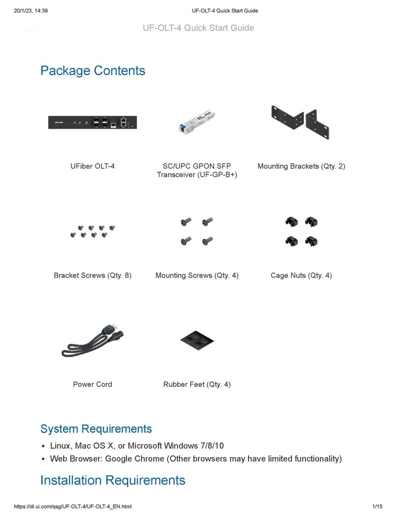
UF

ber OLT SC/UPC GPON SFP Transce

ver
(UF
‐
GP
‐
B+) Mount

ng Brackets (Qty. 2)
Bracket Screws (Qty. 8) Mount

ng Screws (Qty. 4) Cage Nuts (Qty. 4)
Power Cord Rubber Feet (Qty. 4)
Package Contents
System Requ

rements
L

nux, Mac OS X, or M

crosoft W

ndows 7/8/10
Web Browser: Google Chrome (Other browsers may have l

m

ted funct

onal

ty)
Installat

on Requ

rements
Ph

ll

ps screwdr

ver (for rack- or wall-mount

ng)
Standard-s

zed, 19" w

de rack w

th a m

n

mum of 1U he

ght ava

lable (for rack-
mount

ng)
UF-OLT Qu

ck Start Gu

de
19.02.2020 UF-OLT Quck Start Gude
https://dl.ubnt.com/qsg/UF-OLT/UF-OLT_EN.html 2/14
System LED
PON LED (Ports 1 - 8)
SFP+ LED (Ports 1 - 2)
Compat

ble PON SFP and SFP+ transce

vers w

th appropr

ate f

ber opt

c cabl

ng and
accessor

es. For

nformat

on about compat

ble f

ber transce

vers, v

s

t:
ubnt.l

nk/UF

ber-OLT-Modules
Before You Beg

n
Des

gn

ng your f

rst GPON deployment requ

res spec

f

c knowledge and plann

ng. For

nformat

on on GPON network des

gn and

nstallat

on,

nclud

ng

mportant
cons

derat

ons and best pract

ces, refer to:
ubnt.l

nk/UF

ber-GPON-Gett

ng-Started
ubnt.l

nk/Des

gn

ng-a-GPON-Network
For deta

ls on conf

gur

ng UF

ber dev

ces for the f

rst t

me to allow ONU LAN ports to
prov

de connect

v

ty, refer to:
ubnt.l

nk/UF

ber-In

t

al-Conf

gurat

on
Hardware Overv

ew
Blue/Flash

ng In

t

al

z

ng/Boot

ng Up
Wh

te Ready for Use
Off No L

nk
Wh

te/Flash

ng GPON L

nk/Act

v

ty
Off No L

nk
UF-OLT Qu

ck Start Gu

de
19.02.2020 UF-OLT Quck Start Gude
https://dl.ubnt.com/qsg/UF-OLT/UF-OLT_EN.html 3/14
MGMT LED
GPON (Ports PON 1 - 8)
SFP+ (Ports 1 - 2)
MGMT Port
Console Port
Reset Button
Green/Flash

ng 1G L

nk/Act

v

ty
Wh

te/Flash

ng 10G L

nk/Act

v

ty
Off No L

nk
Amber/Flash

ng 10/100 L

nk/Act

v

ty
Green/Flash

ng 1000 L

nk/Act

v

ty
G

gab

t Pass

ve Opt

cal Network ports support up to 128 cl

ents on each port.
Hot-swappable SFP+ ports support 1G or 10G connect

ons.
10/100/1000 Ethernet port used for out
‐
of
‐
band management. For f

rmware vers

on
4.1 and newer,

t

s set to DHCP Cl

ent w

th the fallback IP address, 192.168.1.20/24.
Note:
Prev

ous f

rmware vers

ons default to a stat

c IP: 192.168.1.1.
RJ45 ser

al console port for Command L

ne Interface (CLI) management. Use an
RJ45-to-DB9, ser

al console cable, also known as a rollover cable, to connect the
Console port to your computer. (If your computer does not have a DB9 port, then
you w

ll also need a DB9 adapter.) Then conf

gure the follow

ng sett

ngs as needed:
Baud rate 57600
Data b

ts 8
Par

ty NONE
Stop b

ts 1
Flow control NONE
There are two methods to reset the dev

ce to factory defaults:
Runt

me reset (recommended)
The dev

ce should be runn

ng after bootup

s
complete. Press and hold the Reset button for about 10

seconds unt

l the MGMT
LED starts ash

ng and then becomes sol

dly l

t. After a few seconds, the LED w

ll
turn off, and the dev

ce w

ll automat

cally reboot.
UF-OLT Qu

ck Start Gu

de
19.02.2020 UF-OLT Quck Start Gude
https://dl.ubnt.com/qsg/UF-OLT/UF-OLT_EN.html 4/14
AC/DC PSU Module
PSU 2 Module Bay
Note:
To press the Reset button,

nsert a stra

ghtened paper cl

p (or
s

m

lar object)

nto the hole shown above. Do not use an object that
can break and become lodged

n the hole.
Power-on reset
D

sconnect power from the dev

ce. Press and hold the Reset
button wh

le connect

ng power to the dev

ce. Keep hold

ng the button unt

l the
MGMT LED starts ash

ng and then stops ash

ng after a few seconds.
One AC/DC 100W power supply

s

ncluded. You also have the opt

on to use a
DC/DC PowerModule™, model RPS-DC-100W (sold separately).
For redundancy, you can add an AC/DC PowerModule, model RPS-AC-100W, or a
DC/DC PowerModule (sold separately).
Hardware Installat

on
1.
2.

UF-OLT Qu

ck Start Gu

de
19.02.2020 UF-OLT Quck Start Gude
https://dl.ubnt.com/qsg/UF-OLT/UF-OLT_EN.html 5/14
OR
UF-OLT Qu

ck Start Gu

de
19.02.2020 UF-OLT Quck Start Gude
https://dl.ubnt.com/qsg/UF-OLT/UF-OLT_EN.html 6/14
3.
4.
Connect

ng a PON Module
UF-OLT Qu

ck Start Gu

de
19.02.2020 UF-OLT Quck Start Gude
https://dl.ubnt.com/qsg/UF-OLT/UF-OLT_EN.html 7/14
WARNING:
Never look d

rectly

nto the ends of f

ber or modules. The em

tted
l

ght could cause damage to the eye.
WARNING:
Unt

l ready for use, keep modules and f

ber patch cables covered
us

ng the

ncluded protect

ve caps to ensure the connect

ons stay clean.
Note:
One GPON SFP transce

ver (model UF-GP-B+)

s

ncluded. Use a
compat

ble PON SFP transce

ver w

th the appropr

ate f

ber opt

c cabl

ng for
each PON port. For

nformat

on on compat

ble f

ber transce

vers, v

s

t:
ubnt.l

nk/UF

ber-OLT-Modules
1.
2.
UF-OLT Qu

ck Start Gu

de
19.02.2020 UF-OLT Quck Start Gude
https://dl.ubnt.com/qsg/UF-OLT/UF-OLT_EN.html 8/14
3.
Connect

ng SFP+
1.
2.
UF-OLT Qu

ck Start Gu

de
19.02.2020 UF-OLT Quck Start Gude
https://dl.ubnt.com/qsg/UF-OLT/UF-OLT_EN.html 9/14
3.
Access

ng the Conf

gurat

on Interface
The follow

ng

nstruct

ons apply to f

rmware vers

on 4.1 and newer.
Note:
Prev

ous f

rmware vers

ons default to a stat

c IP: 192.168.1.1.
1. Connect an Ethernet cable from the MGMT port on the dev

ce to a LAN segment
that has an ex

st

ng DHCP server.
UF-OLT Qu

ck Start Gu

de
19.02.2020 UF-OLT Quck Start Gude
https://dl.ubnt.com/qsg/UF-OLT/UF-OLT_EN.html 10/14
2. To check the IP address of the dev

ce, use one of the follow

ng methods:
Set up the DHCP server to prov

de a spec

f

c IP address to the dev

ce based on

ts
MAC address (on the label).
Let the dev

ce obta

n an IP address and then check the DHCP server to see wh

ch
IP address was ass

gned.
3. Launch your web browser. Enter the appropr

ate IP address

n the address f

eld. Press
enter (PC) or return (Mac).
4. Enter ubnt

n the Username and Password f

elds. Cl

ck Log

n.
Custom

ze sett

ngs as needed. For more

nformat

on, refer to the UF

ber resources,
wh

ch are ava

lable at:
http://ubnt.l

nk/UF

ber-Support
Install

ng UNMS
UF-OLT Qu

ck Start Gu

de
19.02.2020 UF-OLT Quck Start Gude
https://dl.ubnt.com/qsg/UF-OLT/UF-OLT_EN.html 11/14
The Ub

qu

t

® Network Management System (UNMS™)

s a L

nux-based controller
software used to centrally manage the UF

ber OLT and cl

ents.
For the latest UNMS vers

on or controller

nformat

on, v

s

t:
www.unms.com
Spec

f

cat

ons
UF-OLT
D

mens

ons 442.4 x 285.6 x 43.7 mm
(17.42 x 11.24 x 1.72")
We

ght

W

thout Mount Brackets 4.400 kg (9.70 lb)
W

th Mount Brackets 4.495 kg (9.91 lb)
Max. Power Consumpt

on 40W (Exclud

ng SFP Transce

vers)
Power Method 110 - 240VAC Modular PSU
Power Supply (1) Hot-Swappable AC/DC 100W PSU (Included)
Supported Voltage Range AC Input: 100 to 240VAC
Button Reset
Processor MIPS 1004Kc 880 MHz Dual-Core
System Memory 512 MB DDR3, 512 MB NAND
LEDs

System Status
PON Data Ports L

nk/Act

v

ty
SFP+ Data Ports L

nk/Act

v

ty
RJ45 (MGMT) Port L

nk/Act

v

ty
Interfaces

UF-OLT Qu

ck Start Gu

de
19.02.2020 UF-OLT Quck Start Gude
https://dl.ubnt.com/qsg/UF-OLT/UF-OLT_EN.html 12/14
UF-OLT
Data Ports (8) GPON Ports (2.488 Gbps TX/1.244 Gbps RX per
Port)
(2) 1G/10G SFP+ Ports
Ser

al Console Port (1) RJ45 Ethernet Port
(1) RJ45 Ser

al Port
Rackmount Yes
Operat

ng Temperature -10 to 45° C (14 to 113° F)
Operat

ng Hum

d

ty 10 - 90% Noncondens

ng
Cert

f

cat

ons CE, FCC, IC
GPON SFP OLT Transce

ver
(UF-GP-B+ ) S

ngle F

ber, SM SC/UPC, 20 km,
1490 nm TX/1310 nm RX,
ITU-T G984.2 Class B+
Safety Not

ces
1. Read, follow, and keep these

nstruct

ons.
2. Heed all warn

ngs.
3. Only use attachments/accessor

es spec

f

ed by the manufacturer.
WARNING:
Fa

lure to prov

de proper vent

lat

on may cause f

re hazard. Keep at least 20
mm of clearance next to the vent

lat

on holes for adequate a

row.
WARNING:
To reduce the r

sk of f

re or electr

c shock, do not expose th

s product to ra

n
or mo

sture.
WARNING:
Do not use th

s product

n locat

on that can be submerged by water.
WARNING:
Avo

d us

ng th

s product dur

ng an electr

cal storm. There may be a remote
r

sk of electr

c shock from l

ghtn

ng.
WARNING:
CLASS 1 LASER PRODUCT - Do not look

nto the ends of the f

ber opt

c cable
or SFP modules wh

le converters are powered.
Electr

cal Safety Informat

on
1. Compl

ance

s requ

red w

th respect to voltage, frequency, and current requ

rements

nd

cated
on the manufacturer’s label. Connect

on to a d

fferent power source than those spec

f

ed may
result

n

mproper operat

on, damage to the equ

pment or pose a f

re hazard

f the l

m

tat

ons
are not followed.
2. There are no operator serv

ceable parts

ns

de th

s equ

pment. Serv

ce should be prov

ded only
by a qual

f

ed serv

ce techn

c

an.
3. Th

s equ

pment

s prov

ded w

th a detachable power cord wh

ch has an

ntegral safety ground
w

re

ntended for connect

on to a grounded safety outlet.
UF-OLT Qu

ck Start Gu

de
19.02.2020 UF-OLT Quck Start Gude
https://dl.ubnt.com/qsg/UF-OLT/UF-OLT_EN.html 13/14
a. Do not subst

tute the power cord w

th one that

s not the prov

ded approved type. Never
use an adapter plug to connect to a 2-w

re outlet as th

s w

ll defeat the cont

nu

ty of the
ground

ng w

re.
b. The equ

pment requ

res the use of the ground w

re as a part of the safety cert

f

cat

on,
mod

f

cat

on or m

suse can prov

de a shock hazard that can result

n ser

ous

njury or death.
c. Contact a qual

f

ed electr

c

an or the manufacturer

f there are quest

ons about the

nstallat

on pr

or to connect

ng the equ

pment.
d. Protect

ve earth

ng

s prov

ded by L

sted AC adapter. Bu

ld

ng

nstallat

on shall prov

de
appropr

ate short-c

rcu

t backup protect

on.
e. Protect

ve bond

ng must be

nstalled

n accordance w

th local nat

onal w

r

ng rules and
regulat

ons.
L

m

ted Warranty
u

.com/support/warranty
The l

m

ted warranty requ

res the use of arb

trat

on to resolve d

sputes on an

nd

v

dual bas

s, and,
where appl

cable, spec

fy arb

trat

on

nstead of jury tr

als or class act

ons.
Compl

ance
FCC
Changes or mod

f

cat

ons not expressly approved by the party respons

ble for compl

ance could
vo

d the user’s author

ty to operate the equ

pment.
Th

s dev

ce compl

es w

th Part 15 of the FCC Rules. Operat

on

s subject to the follow

ng two
cond

t

ons.
1. Th

s dev

ce may not cause harmful

nterference, and
2. Th

s dev

ce must accept any

nterference rece

ved,

nclud

ng

nterference that may cause
undes

red operat

on.
Th

s equ

pment has been tested and found to comply w

th the l

m

ts for a Class A d

g

tal dev

ce,
pursuant to Part 15 of the FCC Rules. These l

m

ts are des

gned to prov

de reasonable protect

on
aga

nst harmful

nterference when the equ

pment

s operated

n a commerc

al env

ronment. Th

s
equ

pment generates, uses, and can rad

ate rad

o frequency energy and,

f not

nstalled and used

n accordance w

th the

nstruct

on manual, may cause harmful

nterference to rad

o
commun

cat

ons. Operat

ons of th

s equ

pment

n a res

dent

al area

s l

kely to cause harmful

nterference

n wh

ch case the user w

ll be requ

red to correct the

nterference at h

s own expense.
ISED Canada
CAN ICES-3(A)/NMB-3(A)
Austral

a and New Zealand
Warn

ng: Th

s equ

pment

s compl

ant w

th Class A of CISPR 32. In a res

dent

al
env

ronment th

s equ

pment may cause rad

o

nterference.
CE Mark

ng
CE mark

ng on th

s product represents the product

s

n compl

ance w

th all d

rect

ves that are
appl

cable to

t.
UF-OLT Qu

ck Start Gu

de
19.02.2020 UF-OLT Quck Start Gude
https://dl.ubnt.com/qsg/UF-OLT/UF-OLT_EN.html 14/14
WEEE Compl

ance Statement
Declarat

on of Conform

ty
Onl

ne Resources
© 2020 Ub

qu

t

Inc. All r

ghts reserved.
UF-OLT Qu

ck Start Gu

de

This manual suits for next models

1

Other Ubiquiti Network Hardware manuals

Ubiquiti PowerBeam PBE-5AC-500 User manual
Ubiquiti

Ubiquiti PowerBeam PBE-5AC-500 User manual

Ubiquiti airVision-C User manual

Ubiquiti

Ubiquiti airVision-C User manual

Ubiquiti UBB User manual

Ubiquiti

Ubiquiti UBB User manual

Ubiquiti M900 User manual

Ubiquiti

Ubiquiti M900 User manual

Ubiquiti UniFi Cloud Key Gen2 Plus User manual

Ubiquiti

Ubiquiti UniFi Cloud Key Gen2 Plus User manual

Ubiquiti UniFi WiFi BaseStation XG User manual
Ubiquiti

Ubiquiti UniFi WiFi BaseStation XG User manual

Ubiquiti PowerBeam airMAX AC Gen2 PBE-5AC-Gen2 User manual
Ubiquiti

Ubiquiti PowerBeam airMAX AC Gen2 PBE-5AC-Gen2 User manual

Ubiquiti UniFi Dream Machine Pro User manual

Ubiquiti

Ubiquiti UniFi Dream Machine Pro User manual

Ubiquiti PowerBeam M PBE-M2-400 User manual

Ubiquiti

Ubiquiti PowerBeam M PBE-M2-400 User manual

Ubiquiti PowerBeam PBE-5AC-500-ISO User manual

Ubiquiti

Ubiquiti PowerBeam PBE-5AC-500-ISO User manual

Ubiquiti U-Installer User manual

Ubiquiti

Ubiquiti U-Installer User manual
Ubiquiti PowerBeam PBE-2AC-400-US User manual

Ubiquiti

Ubiquiti PowerBeam PBE-2AC-400-US User manual

Ubiquiti UniFi US-24-250W User manual

Ubiquiti

Ubiquiti UniFi US-24-250W User manual

Ubiquiti PowerBeam M5 PBE-M5-400 User manual

Ubiquiti

Ubiquiti PowerBeam M5 PBE-M5-400 User manual

Ubiquiti PowerBeam AC Gen2 User manual

Ubiquiti

Ubiquiti PowerBeam AC Gen2 User manual

Ubiquiti UniFi Dream Machine Pro User manual

Ubiquiti

Ubiquiti UniFi Dream Machine Pro User manual

Ubiquiti EdgeSwtch 5XP User manual

Ubiquiti

Ubiquiti EdgeSwtch 5XP User manual

Ubiquiti PowerBeam M5 User manual

Ubiquiti

Ubiquiti PowerBeam M5 User manual

Ubiquiti PBE-5AC-GEN2-5-EU User manual

Ubiquiti

Ubiquiti PBE-5AC-GEN2-5-EU User manual

Ubiquiti Nano G User manual

Ubiquiti

Ubiquiti Nano G User manual

Ubiquiti UniFi UAP User manual

Ubiquiti

Ubiquiti UniFi UAP User manual

Ubiquiti R5AC-PTP User manual

Ubiquiti

Ubiquiti R5AC-PTP User manual

Ubiquiti RocketDish RD-5G30 User manual

Ubiquiti

Ubiquiti RocketDish RD-5G30 User manual

Ubiquiti airFiber 60 User manual

Ubiquiti

Ubiquiti airFiber 60 User manual

Popular Network Hardware manuals by other brands

ExtraHop Trace Admin UI Guide

ExtraHop

ExtraHop Trace Admin UI Guide

Nexcom FTA 1170 Series user manual

Nexcom

Nexcom FTA 1170 Series user manual

Softing TH LINK installation manual

Softing

Softing TH LINK installation manual

ADC ETP-64 Specification sheet

ADC

ADC ETP-64 Specification sheet

SIM Roulette SR-Train user manual

SIM Roulette

SIM Roulette SR-Train user manual

Win PL-10600 user manual

Win

Win PL-10600 user manual

Seagate Exos AP 4U100 Installation and maintenance guide

Seagate

Seagate Exos AP 4U100 Installation and maintenance guide

Freescale Semiconductor CodeWarrior TAP user guide

Freescale Semiconductor

Freescale Semiconductor CodeWarrior TAP user guide

C&H M/MA Module Carrier AMi3000 Specifications

C&H

C&H M/MA Module Carrier AMi3000 Specifications

Spica Door Cloud Quick connection guide

Spica

Spica Door Cloud Quick connection guide

Seiko NS-2250 instruction manual

Seiko

Seiko NS-2250 instruction manual

Black Box JPM5E24A-HU manual

Black Box

Black Box JPM5E24A-HU manual

CopperOptics PairGain PG-Flex FCS-718 manual

CopperOptics

CopperOptics PairGain PG-Flex FCS-718 manual

Allied Telesis ADSL24AE Specifications

Allied Telesis

Allied Telesis ADSL24AE Specifications

Elvox 46241.H04 user manual

Elvox

Elvox 46241.H04 user manual

Canon VK-16 v2.1 Operation guide

Canon

Canon VK-16 v2.1 Operation guide

AMX AXC-IR/S instruction manual

AMX

AMX AXC-IR/S instruction manual

Enable-IT 360 quick start guide

Enable-IT

Enable-IT 360 quick start guide

manuals.online logo
manuals.online logoBrands
  • About & Mission
  • Contact us
  • Privacy Policy
  • Terms and Conditions

Copyright 2025 Manuals.Online. All Rights Reserved.