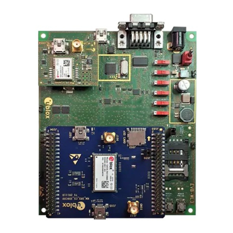
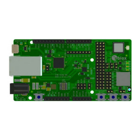
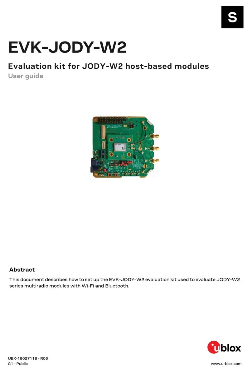
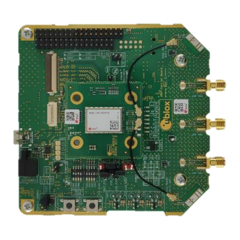
Ublox EVK-JODY-W3 User manual

EVK-JODY-W3 - User guide
UBX-20030840 - R04 Document information Page 2 of 29
C1 –Public
Document information
Title
EVK-JODY-W3
Subtitle
Evaluation kit for JODY-W3 host-based modules
Document type
User guide
Document number
UBX-20030840
Revision and date
R04
17-Nov-2021
Disclosure restriction
C1 –Public
This document applies to the following products:
Product name
Type number
Hardware version
PCN reference
EVK-JODY-W374
EVK-JODY-W374-00A-00
Module board rev. B
Carrier board rev. D
N/A
EVK-JODY-W377
EVK-JODY-W377-00A-00
N/A
u-blox or third parties may hold intellectual property rights in the products, names, logos and designs included in this
document. Copying, reproduction, modification or disclosure to third parties of this document or any part thereof is only
permitted with the express written permission of u-blox.
The information contained herein is provided “as is” and u-blox assumes no liability for its use. No warranty, either express or
implied, is given, including but not limited to, with respect to the accuracy, correctness, reliability and fitness for a particular
purpose of the information. This document may be revised by u-blox at any time without notice. For the most recent
documents, visit www.u-blox.com.
Copyright © u-blox AG.

EVK-JODY-W3 - User guide
UBX-20030840 - R04 Contents Page 3 of 29
C1 –Public
Contents
1.1 Overview........................................................................................................................................................4
1.2 Kit includes...................................................................................................................................................6
1.3 Software........................................................................................................................................................7
1.4 System requirements ................................................................................................................................7
1.5 Operating conditions..................................................................................................................................8
3.1 Block diagram ............................................................................................................................................11
3.2 Jumpers and connectors ........................................................................................................................12
3.2.1 Jumper and switch configuration options ..................................................................................13
3.2.2 Jumper conventions ........................................................................................................................13
3.3 Power supply configuration ....................................................................................................................14
3.3.1 Selecting the EVB power supply....................................................................................................15
3.3.2 Selecting the module input voltage ..............................................................................................16
3.4 Bootstrapping............................................................................................................................................18
3.5 PCIe interface.............................................................................................................................................19
3.6 SDIO interface............................................................................................................................................20
3.7 Bluetooth host interface..........................................................................................................................21
3.8 Bluetooth audio interface........................................................................................................................21
3.9 Antenna interfaces...................................................................................................................................22
3.9.1 EVK-JODY-W374 antenna connections......................................................................................23
3.9.2 EVK-JODY-W377 antenna connections......................................................................................23
3.10Other interfaces ........................................................................................................................................24
3.11LEDs.............................................................................................................................................................24
3.12Reset buttons ............................................................................................................................................25
3.13Schematics.................................................................................................................................................25

EVK-JODY-W3 - User guide
UBX-20030840 - R04 Kit description Page 4 of 29
1Kit description
JODY-W3 series modules provide complete short-range transceiver solutions based on the NXP
chipset 88Q9098.
Intended for the most advanced in-car infotainment and connectivity systems, JODY-W3 series
modules deliver the highest data rates in Wi-Fi using advanced Wi-Fi 6 802.11ax technology. The
modules operate in concurrent dual-bands, Wi-Fi 2.4 and 5 GHz, dual-MAC, and 2x2 MIMO, and
support Bluetooth 5.1 features like extended advertising, long range, and 2 Mbit/s (PHY) data rates.
The modules require a host processor running Linux or Android and connect to the host processor
through either PCIe or SDIO for Wi-Fi, SDIO or high-speed UART for Bluetooth, and PCM/I2S for
Bluetooth audio.
EVK-JODY-W3 allows an external host processor to access several practical features for testing and
evaluating the Wi-Fi and Bluetooth connectivity supported in JODY-W3 series modules, including:
•External connectors to all host interfaces (PCIe, SDIO and UART)
•USB interface for easy access the Bluetooth UART interface through a USB-to-UART bridge
•Digital and analog audio interfaces for Bluetooth
•Two internal dual-band 2.4/5 GHz antennas for Wi-Fi and Bluetooth.
•Three SMA connectors for external antennas.
•GPIO pins and other module interfaces are accessible through pin headers
•Multiple power supply options
For more information about JODY-W3 modules, see the JODY-W3 series data sheet [1] and system
integration manual [2].
1.1 Overview
Table 1 lists the available evaluation kit versions:
Evaluation kit
Ordering code
Description
Suitable for evaluation of
EVK-JODY-W374
EVK-JODY-W374-00A
Evaluation kit for JODY-W374
Two antennas for simultaneous dual-band
Wi-Fi (1x1 2.4 GHz and 2x2 5 GHz) and
Bluetooth 5.1
JODY-W374-00A
EVK-JODY-W377
EVK-JODY-W377-00A
Evaluation kit for JODY-W377
Three antennas for simultaneous dual-band
Wi-Fi (2x2 2.4 GHz and 2x2 5 GHz) and a
dedicated antenna for Bluetooth 5.1
JODY-W377-00A
Table 1: Available EVK-JODY-W3 evaluation kits

EVK-JODY-W3 - User guide
UBX-20030840 - R04 Kit description Page 5 of 29
Figure 1 shows the main components of the EVK-JODY-W3 evaluation board.
Figure 1: EVK-JODY-W3 outline showing main interfaces and connectors
The evaluation board design includes a module board and a carrier board:
•The module board includes the JODY-W3 module and U.FL antenna connectors that connect
directly to the antenna pins on the module.
•The larger carrier board hosts the module board and includes all the necessary connectors for
connecting the JODY-W3 series module to the host system.
Internal dual-band
antenna
Internal dual-
band antenna
SDIO
connector
USB connector
through FTDI
SMA connectors for
external antennas
GPIOs
PCM/I2S
interface
UART
pins
PCIe
connector
U.FL coaxial
cable connector
Module board
Evaluation
board (EVB)

EVK-JODY-W3 - User guide
UBX-20030840 - R04 Kit description Page 6 of 29
1.2 Kit includes
Table 2 shows the various components included in the EVK-JODY-W3.
Part
Description
Outline
Evaluation
board
(EVB)
Evaluation board for the JODY-W3 series modules.
The board includes SMA antenna connectors that
connect to external antennas for Wi-Fi and Bluetooth. It
also supports two internal dual-band Wi-Fi/Bluetooth
antennas.
M.2 PCIe
to ZIF
adapter
M.2 PCIe to ZIF adapter for Wi-Fi host communication.
One flat ZIF cable is included for both PCIe adapters.
Mini-PCIe
to ZIF
adapter
Mini-PCIe to ZIF adapter for Wi-Fi host communication.
One flat ZIF cable is included for both PCIe adapters.
Micro
SDIO to
ZIF
adapter
and flat
ZIF cable
Micro SDIO to ZIF adapter and flat cable for Wi-Fi and/or
Bluetooth host communication. The adapter is
compatible with host sockets designed for micro-SD
memory cards.
Type-C
USB cable
Type-C USB cable for Bluetooth host communication
through the USB-to-UART bridge
External
antennas
2 x Dual band Wi-Fi/Bluetooth antenna,
Linx Technologies ANT-DB1-RAF-SMA
Table 2: EVK-JODY-W3 component list

EVK-JODY-W3 - User guide
UBX-20030840 - R04 Kit description Page 7 of 29
1.3 Software
JODY-W3 series modules are based on the NXP 88Q9098 chipset. The drivers and firmware required
to operate JODY-W3 series modules are developed by NXP and are already integrated into the Linux
BSP for the NXP i.MX application processors [5].
1
The documentation for the software releases from NXP contains Wi-Fi and Bluetooth release notes
and a list of supported software features. The driver source code is provided free of charge as open
source under NXP license terms. Being open source allows the drivers to be integrated or ported to
other non-NXP based host platforms. Yocto recipes for the driver and firmware, that can be used to
develop custom Linux-based systems, are part of the NXP i.MX Linux BSP.
The latest version of the driver source code and Wi-Fi/Bluetooth firmware are available from the
following open-source repositories:
•Wi-Fi driver: https://source.codeaurora.org/external/imx/mwifiex/
•Firmware: https://github.com/NXP/imx-firmware/
☞Use the repository branches matching to the latest Linux BSP release version. At the time of
publication, this is release 5.10.52_2.1.0.
The Wi-Fi driver uses the TCP/IP stack from the Linux kernel for data transmission and the cfg80211
subsystem in the kernel for configuration and control. The hci_uart driver from the Linux kernel and
BlueZ host stack are used for the Bluetooth part. For further information about initialization and
configuration of the Wi-Fi and Bluetooth features, see also the JODY-W3 system integration
manual [2] and the NXP User Manual UM11490 [6].
Contact your local u-blox support team for information about additional software options for the
JODY-W3 series modules.
1.4 System requirements
The evaluation kit has the following system requirements:
•Host (PC or embedded system) with
oMini-PCIe or M.2 Key E slot for access to Wi-Fi through the PCIe 2.0 host interface
oMicro SDIO slot for access to Wi-Fi through the SDIO 3.0 host interface
oUSB 2.0 interface for access to the Bluetooth UART interface through USB-to-UART bridge
•Supported operating systems
oLinux (3.x/4.x/5.x)
oAndroid
1
Drivers for PCIE-UART are currently supported. SDIO-UART support is planned for Q1/2022.

EVK-JODY-W3 - User guide
UBX-20030840 - R04 Kit description Page 8 of 29
1.5 Operating conditions
Table 3 describes the recommended operating conditions for the EVK-JODY-W3. For more
information about power supply requirements, see also the JODY-W3 series data sheet [1].
Symbol
Parameter
Min.
Typ.
Max.
Units
3V3 / VDD_PCIE
/ VDD_SDIO
Module 3.3 V power supply voltage from external
source (J101), PCIe, or SDIO
3.14
3.3
3.46
V
VIO
Module I/O
supply voltage
(J102)
1.8 V
1.71
1.8
1.89
V
3.3 V
3.14
3.3
3.46
V
1V8
Module analog power supply voltage 1.8 V (J103)
1.71
1.8
1.89
V
VDD_SYS
EVB external power supply (J11/J100)
4.5
25.4
V
VDD_USB3
EVB power supply from USB
4.5
5
5.5
V
TA
Ambient operating temperature
-40
-
+85*
ºC
Ripple Noise
Peak-to-peak voltage ripple on all supply lines.
-
-
30
mV
Table 3: EVK-JODY-W3 operating conditions
☞The signal voltage for the SDIO interface of the JODY-W3 series module is powered from the
1V8 supply. A level shifter is required to operate the module in Default Speed and High-Speed
modes at 3.3 V signal voltage [3]. Contact your local u-blox support team for further
information.

EVK-JODY-W3 - User guide
UBX-20030840 - R04 Getting started Page 9 of 29
2Getting started
This chapter describes the basic settings and procedures to get started with EVK-JODY-W3.
☞An overview of the EVB and its main connectors is shown in Figure 1. For more detailed
description of the available connectors and configuration options, see Board description.
Follow the procedure below to evaluate JODY-W3 series module using EVK-JODY-W3:
1. Connect the coaxial cables to the U.FL connectors on the module board and internal antennas on
the carrier board; or to SMA connectors for use with external antennas or conducted test setup.
The default antenna configuration is described below:
oEVK-JODY-W374 uses both of its two internal dual-band antennas for Wi-Fi and Bluetooth
communication.
oEVK-JODY-W377 uses one of its two internal antennas for Bluetooth, and Wi-Fi
communication is configured for use through SMA connectors SMA1 and SMA2. Connect
the two supplied external antennas to the selected SMA connectors on the EVB.
For more information about the antenna configuration, see also Antenna interfaces.
2. Set DIP switch SW503 to select the host interfaces for Wi-Fi and Bluetooth from the possible
combinations PCIE-UART, SDIO-UART or SDIO-SDIO, as described in Bootstrapping.
3. Configure the power supply source as described in Power supply configuration and shown in
Table 5. The most common configuration uses the Wi-Fi host interface as the supply source,
which can be either PCIe or SDIO.
4. Connect the host interfaces to the host system. The EVB and supplied PCIe and SDIO adapters
use zero insertion force (ZIF) connectors with flat cables for connecting the adapters. To connect
the cable, gently flip up the small locking flap of the connector, align and insert the flat cable with
the blue marking pointing upwards, and then close the locking flap.
oFor PCIe connection to the host, use either the M.2 or the mini-PCIe adapter depending on
the available connector on the host platform. First, plug the adapter into the PCIe connector
on the host system. Then connect it with the flat cable to the connector (J203) on the EVB,
as shown in Figure 2. The PCIe interface can be used for Wi-Fi communication with the
JODY-W3 series module.
Figure 2: PCIe and USB connectors
J203
(PCIe)
Coaxial cable with
U.FL connector
Internal
antenna (1)
Internal
antenna (2)
SW503
SMA2
SMA1
SMA0

EVK-JODY-W3 - User guide
UBX-20030840 - R04 Getting started Page 10 of 29
oFor SDIO connection, connect the supplied micro SDIO adapter card with the flat cable to the
SDIO connector (J204) on the EVB, as shown in Figure 3. Insert the adapter card into an SDIO
connector of the host system. The SDIO interface can be used for Wi-F and optionally
Bluetooth communication with the JODY-W3 series module.
Figure 3: SDIO and USB connectors
oA high speed UART interface can be used for Bluetooth communication with the JODY-W3
series module. A USB-to-UART bridge is included on the evaluation board. To use the Bluetooth
interface through USB, connect the supplied USB cable to the USB type-C connector on the
EVB and connect it to a USB interface on the host system. Make sure that jumper J400 is
bridged (default setting) to enable Bluetooth communication over USB. For information about
accessing the UART interface for Bluetooth directly, see also Bluetooth host interface.
5. Power on the host system. The LEDs on the EVB indicate the status of the different voltage rails
and should turn green to indicate proper power supply. At this point, the module should be
detected by the host system.
6. Install the necessary driver software for the JODY-W3 module, as described in the JODY-W3
system integration manual [2].
SDIO
(J204)
USB type-C
connector
UART
(J305)
USB-to-UART
enable (J400)
SDIO
adapter
Status
LEDs

EVK-JODY-W3 - User guide
UBX-20030840 - R04 Board description Page 11 of 29
3Board description
This chapter describes the logical components, connectors, jumpers, and switches used to configure
the EVK-JODY-W3.
3.1 Block diagram
Figure 4 shows the block diagram of the EVB and the logical connections between the JODY-W3
module and the various peripherals around it.
Figure 4: EVK-JODY-W3 block diagram
JODY-W3
module
2x internal
dual-band
antennas
3x SMA
connectors
Control lines
and GPIOs
Audio interface
(PCM/I2S)
PCIe
interface
UART
interface
USB
interface
UART to
USB
SDIO
interface
DC-DC
Bootstrap
configuration
Audio
codec
Power supply

EVK-JODY-W3 - User guide
UBX-20030840 - R04 Board description Page 12 of 29
3.2 Jumpers and connectors
Figure 5 shows an outline of the evaluation board and the placement of the connectors, jumpers, and
switches. The EVB makes all interfaces of the JODY-W3 module accessible through connectors or pin
headers. See also Jumper and switch configuration options
Figure 5: EVK-JODY-W3 jumpers and connectors
J411 (LEDs)
JODY-W3
module
board
ANT400
ANT401
J406
J408
J410
SW501
SW500
SW503
J301
J303
J302
J300
J204 (SDIO)
J203 (PCIe)
J11
J100
S1
Power mux
J400
J205 (bottom USB)
J401/
J402
J305
Input
voltage
selection
J103-J101 (bottom)
J206 (bottom
audio jack)

EVK-JODY-W3 - User guide
UBX-20030840 - R04 Board description Page 13 of 29
3.2.1 Jumper and switch configuration options
Table 4 provides a summary of the connectors and jumpers used to configure EVK-JODY-W3.
Designator
Connector
Description
J104-J106
Power supply selection
(power mux)
Jumper settings for external power supply selection.
See also External power supply selection.
J1-J7
Input voltage selection
Jumper settings for selecting the input voltages for the module. See also
Input voltage selection.
SW503
Bootstrapping
Switch for host interface selection.
See also Bootstrapping.
J203
PCIe connector
ZIF connector for PCIe host interface on EVB.
See also PCIe interface.
J204
SDIO connector
ZIF connector for SDIO host interface on EVB.
See also SDIO interface.
J205
Type-C USB
USB connector for Bluetooth host interface (through USB-to-UART bridge).
See also Bluetooth host interface.
J400
USB-UART Enable
Jumper to enable/disable the Bluetooth host interface through
USB-to-UART bridge
J305
Bluetooth UART
UART connector for Bluetooth host interface.
See also Bluetooth host interface.
J401, J402
Audio codec enable
Jumpers to enable the audio codec on the EVB (3.8)
J206
Audio jack
Audio jack for the audio codec.
See also Bluetooth audio interface.
J301
Bluetooth audio
Connector for the PCM/I2S audio interface.
See also Bluetooth audio interface.
J300, J302, J303
Control lines
Connector for host and device wake for Bluetooth and Wi-Fi.
See also Other interfaces.
J406, J408, J410
SMA connectors
SMA coaxial RF connectors for external antennas.
See also Antenna interfaces.
ANT400, ANT401
Internal antennas
Internal dual-band chip antennas.
See also Antenna interfaces.
SW500, SW501
Reset buttons
Reset buttons for module and power supply.
See also Reset buttons.
S1
Power enable switch
External EVB power supply switch
J11, J100
Power jack
Power jack and connector for common external EVB supply
J101-J103
External supply
Connectors for individual external supplies
J411
LEDs
Jumper to enable power supply LEDs.
See also LEDs.
Table 4: JODY-W3 evaluation board connectors
3.2.2 Jumper conventions
Figure 6 shows the graphical conventions used for the jumper settings described in this document.
Pin 0 is shown in grey color. All jumpers are shown with red lines terminated with round edges.
Figure 6: Jumper convention
Jxxx
Pin 0 of the jumper JXXX
Jumper connected between 2 pins

EVK-JODY-W3 - User guide
UBX-20030840 - R04 Board description Page 14 of 29
3.3 Power supply configuration
JODY-W3 series modules must be supplied with 1.8 V (1V8), 3.3 V (3V3), and a VIO voltage that can
be either 1.8 V or 3.3 V. The power supply for the EVB can be provided over the different host
interfaces or from external sources.
The following power supply options are available on the EVB:
•PCIe, SDIO, USB interfaces: The EVB is powered through the host interface. All internal voltages
are generated by DC-DC converters on the EVB.
•Common external power supply: The EVB can be connected to an external (5 V to 24 V) power
supply through a 2.1 x 6.3 mm DC power jack (J11). DC-DC converters are used for generating all
the required internal voltages.
•Separate external supplies: All the individual, 3V3, 1V8,and VIO voltage rails are supplied from
external power sources through the connectors J101-J103.
Figure 7 shows the external connectors and jumpers used for configuring the different power supply
options.
Figure 7: Overview of EVB power supply configuration
Jumpers for input
voltage selection
for the module
Jumper for power
supply selection
Power supply
status LEDs
J101-J103 connectors (bottom
side) for separately supplying the
3V3, 1V8 and VIO voltage rails
Common external
power supply
connector

EVK-JODY-W3 - User guide
UBX-20030840 - R04 Board description Page 15 of 29
To operate the JODY-W3 EVB, the external power supply source (power mux) and input voltage
levels to the module must be configured using jumpers on the EVB. The power supply tree, including
the jumpers on the EVB, is shown in Figure 8. See also Jumpers and connectors.
•J104–J106 configure the EVB power supply source (SDIO, PCIe, USB or external) to the VIN_3V3
domain, which generates the internal power rails for the module.
•J1-J7 configure the input voltages for the JODY-W3 series module, which can be selected
between the internally generated voltages and the external supplies from J103-J103.
DC-DC converters are used to step-down the external and USB supplies to the power mux and
generate the required input voltages for the module.
Figure 8: JODY-W3 EVB power supply tree
3.3.1 Selecting the EVB power supply
Use jumpers J104–J106 to select the EVB power supply (power mux) for the EVB. Figure 9 shows
the arrangement of external power supply sources for each jumper position.
Figure 9: External power supply selection, J104-J106
VIN_3V3 is the input to the DC-DC converter on the EVB that generates the required voltage rails
(3V3_DCDC, 1V8_DCDC, 3V3_VIO, and 1V8_VIO) for the module, as shown in Figure 8. A single
jumper is connected between VIN_3V3 and the chosen voltage supply to the EVB.

EVK-JODY-W3 - User guide
UBX-20030840 - R04 Board description Page 16 of 29
Table 5 shows the (J104–J106) jumper positions for selecting the power supply source for the EVB.
Power supply source
Jumper configuration
3.3 V from PCIe interface
Use the M.2 or mini-PCIe adapter with the flat cable to connect to the host system.
3.3 V from SDIO interface
Use the micro SDIO adapter with the flat cable to connect to the host system.
5 V from USB interface
Use the Type-C USB cable to connect to the host system.
Note: The USB host port must be able to deliver a current of up to 1000 mA for Wi-Fi
operation. The current provided by a standard USB 2.0 interface is sufficient for Bluetooth-
only operation.
5 V –24 V external power supply
External supply must be connected to the power jack J11 or J100. The external supply
voltage is converted to 3.3 V using a DC-DC on the EVB.
J11: 2.1 x 6.3 mm DC power jack
J100: Phoenix Contact 1721986
All input voltages supplied from separate external sources
External supplies must be connected to the power jacks located on the bottom side of the
EVB for 3V3 (J101), 1V8 (J103) and VIO (J102).
J101-J103: Phoenix contact 1721986.
Table 5: Jumper settings for selecting the EVB power supply (J104 –J106)
3.3.2 Selecting the module input voltage
Use jumpers J1-J7 to select the external power source to the module, as shown in Figure 8.
The input voltage to the module can be sourced from either the on-board DC-DC generated voltages
or the direct input voltages from the separate external supplies J101-J103.
Figure 10: Input voltage selection (J1-J7)

EVK-JODY-W3 - User guide
UBX-20030840 - R04 Board description Page 17 of 29
The input voltage options for selecting the module supply are described in Table 6.
Designator
Module supply
Source
3V3
3V3
Can be connected to 3V3_DCDC or 3V3_EXT
VIO
VIO
Can be connected to 3V3_VIO, 1V8_VIO, or VIO_EXT
1V8
1V8
Can be connected to 1V8_DCDC or 1V8_EXT
Table 6: Input voltage options
Table 7 describes the different options for selecting the module input voltages using jumpers J1-J7.
Jumper settings
Description / Voltage levels
VIO (3.3 V)
VIO (1.8 V)
Selects the power supply from the host interface (PCIe,
SDIO or USB) or common external supply (VEXT) and on-
board DC-DC generated voltages.
VIO is derived from either 1V8 or 3V3.
•3V3 –3.3 V
•1V8 –1.8 V
•VIO –1.8 V or 3.3 V
Selects the power supply using separate external input
sources for each of the voltage rails 3V3, 1V8 and VIO.
External supplies are connected to J101-J103 at the
bottom of the EVB carrier board.
Table 7: Jumper settings (J1-J7) for selecting module input voltage

EVK-JODY-W3 - User guide
UBX-20030840 - R04 Board description Page 18 of 29
3.4 Bootstrapping
JODY-W3 supports the following host interface combinations:
•PCIE-UART mode: Commands and data for the Wi-Fi traffic are transferred through the PCIe bus
to the module. The Bluetooth traffic uses the high-speed UART interface.
•SDIO-UART mode: Commands and data for the Wi-Fi traffic is transferred through the SDIO bus
to the module. The Bluetooth traffic uses the high-speed UART interface.
•SDIO-SDIO mode: Commands and data for both the Wi-Fi and Bluetooth traffic is transferred to
the module through the SDIO bus.
2
DIP switch SW503 is used on the EVB to define the boot mode and the physical interfaces used for
Wi-Fi and Bluetooth communication. Set each switch ON to pull the configuration signal low (GND,
logic level “0”), and OFF to pull it high (logic level “1”).
Figure 11: Boot and host interface configuration
Table 8 describes the DIP switch positions for configuring the boot mode and host interface options.
Boot mode
CON_2
CON_1
CON_0
Description
PCIE-UART
ON
OFF
OFF
Wi-Fi through PCIe (J203), Bluetooth through USB-to-UART
(J205) or UART (J305)
SDIO-UART
ON
ON
ON
Wi-Fi through SDIO (J204), Bluetooth through USB-to-UART
(J205) or UART (J305)
SDIO-SDIO
ON
ON
OFF
Wi-Fi and Bluetooth through SDIO (J204)
Table 8: Boot mode selection options
☞The UART interface for Bluetooth can be accessed either directly through J305, or through the
USB type-C connector J205 and USB-to-UART bridge. For further information about the
Bluetooth UART interface, see also Bluetooth host interface.
2
Driver/firmware support for SDIO-SDIO is currently not productized.

EVK-JODY-W3 - User guide
UBX-20030840 - R04 Board description Page 19 of 29
3.5 PCIe interface
The EVB can be connected through a PCIe connector for Wi-Fi communication with the host system.
Adapters for host-side M.2 Key E and mini-PCIe connectors are supplied in the kit.
The PCIe host interface connector (J203) is shown in Figure 12.
Figure 12: PCIe interface connector
VDD_PCIE can be used for supplying the EVB from the PCIe interface.

EVK-JODY-W3 - User guide
UBX-20030840 - R04 Board description Page 20 of 29
3.6 SDIO interface
The EVB can be connected through a micro SDIO connector for Wi-Fi communication with the host
system. The SDIO connector can optionally be used for Bluetooth
3
.
The SDIO host interface connector (J204) is shown in Figure 13.
Figure 13: SDIO interface connector
All signals except VDD_SDIO are directly connected to the JODY-W3 module through 22 Ωseries
resistors connected on the module board.
VDD_SDIO can be used for supplying the EVB from the SDIO interface. The SDIO signals are powered
by the 1V8 voltage domain.
☞Pull-up resistors for the SDIO lines are not installed on the EVB because they are typically
included in the host CPU. The EVB carrier board has the provision to install pull-up resistors if
needed by the design.
3
SDIO support for Bluetooth is currently not productized.
This manual suits for next models
4
Table of contents
Other Ublox Motherboard manuals

Ublox
Ublox EVK-R8 Series User manual

Ublox
Ublox EVK-NORA-W10 User manual

Ublox
Ublox C099-F9P User manual

Ublox
Ublox NORA-W10 Series User manual

Ublox
Ublox EVK-ELLA-W1 User manual

Ublox
Ublox C099-F9P User manual

Ublox
Ublox EVK-M10QSAM User manual

Ublox
Ublox EVK-M8BZOE User manual

Ublox
Ublox EVK-M8U User manual

Ublox
Ublox EVK-R6 User manual

Ublox
Ublox C030-R412M User manual

Ublox
Ublox SARA-N3 series User manual

Ublox
Ublox SARA-R5 Series User manual

Ublox
Ublox EVK-M101 User manual

Ublox
Ublox EVK-M8F-0-01 User manual

Ublox
Ublox EVK-M9DR User manual

Ublox
Ublox C102-F9R User manual

Ublox
Ublox EVK-W262U User manual

Ublox
Ublox EVK-NINA-B4 User manual

Ublox
Ublox EVK-M91 User manual