Ublox EVK-M91-00-01 User manual

EVK-M91
Evaluation kit
User guide
Abstract
This document describes the structure and use of the EVK-M91
evaluation kit and provides information for evaluating and testing u-
blox M9 positioning technology.
www.u-blox.com
UBX-19056858 - R04
C1-Public

EVK-M91-User guide
Document information
Title EVK-M91
Subtitle Evaluation kit
Document type User guide
Document number UBX-19056858
Revision and date R04 07-Oct-2022
Disclosure restriction C1-Public
This document applies to the following products:
Product name Type number Firmware version PCN reference
EVK-M91 EVK-M91-00-01 EXT SPG 4.04, ROM SPG
4.04
N/A
u-blox or third parties may hold intellectual property rights in the products, names, logos and designs included in this
document. Copying, reproduction, or modification of this document or any part thereof is only permitted with the express
written permission of u-blox. Disclosure to third parties is permitted for clearly public documents only.
The information contained herein is provided "as is" and u-blox assumes no liability for its use. No warranty, either express
or implied, is given, including but not limited to, with respect to the accuracy, correctness, reliability and fitness for a
particular purpose of the information. This document may be revised by u-blox at any time without notice. For the most recent
documents, visit www.u-blox.com.
Copyright © 2022, u-blox AG.
UBX-19056858 - R04
Page 2 of 27
C1-Public

EVK-M91-User guide
Contents
1 Product description.............................................................................................................. 5
1.1 Overview.................................................................................................................................................... 5
1.2 Kit contents..............................................................................................................................................5
1.3 System requirements.............................................................................................................................5
2 Specifications......................................................................................................................... 6
2.1 Safety precautions..................................................................................................................................6
3 Getting started...................................................................................................................... 7
3.1 u-center installation............................................................................................................................... 7
3.2 Hardware installation............................................................................................................................. 7
3.3 Serial port default configuration......................................................................................................... 7
4 Approvals..................................................................................................................................9
5 Device description.............................................................................................................. 10
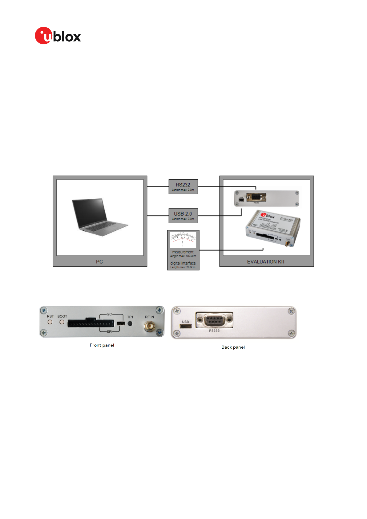
5.1 Interface connection............................................................................................................................ 10
5.1.1 Interface switch............................................................................................................................10
5.1.2 USB..................................................................................................................................................11
5.1.3 UART...............................................................................................................................................11
5.1.4 SPI....................................................................................................................................................12
5.1.5 I2C....................................................................................................................................................12
5.2 GNSS input signal................................................................................................................................ 13
5.2.1 Antenna connector...................................................................................................................... 13
5.3 Time pulse.............................................................................................................................................. 13
5.4 Reset button..........................................................................................................................................13
5.5 Safeboot button....................................................................................................................................13
5.6 LED...........................................................................................................................................................14
5.7 Flash.........................................................................................................................................................14
5.8 Super capacitor.....................................................................................................................................14
5.9 EXTINT.................................................................................................................................................... 14
6 Current measurement....................................................................................................... 15
6.1 GNSS current.........................................................................................................................................15
6.2 Backup current...................................................................................................................................... 15
7 Block diagram.......................................................................................................................16
8 Board layout..........................................................................................................................17
8.1 PCB version B........................................................................................................................................ 17
9 External firmware update and ROM firmware evaluation.......................................18
10 Troubleshooting................................................................................................................ 21
11 Common evaluation pitfalls.......................................................................................... 23
Appendix.................................................................................................................................... 24
A Glossary......................................................................................................................................................24
Related documents................................................................................................................ 25
UBX-19056858 - R04
Contents Page 3 of 27
C1-Public

EVK-M91-User guide
1 Product description
1.1 Overview
EVK-M91 Evaluation Kit makes evaluating the high performance of u-blox M9 positioning
technology simple (see u-blox M9 www.u-blox.com/m9). The built-in USB interface provides both
power supply and high-speed data transfer, keeping the possibility to connect through 14 pin
connector. EVK-M91 has versatile interfaces and measurement points that enable advanced
evaluation needs.
u-blox evaluation kits are compact, and their user-friendly interface and power supply make them
ideally suited for use in laboratories or vehicles. Furthermore, they can be used with a PDA or a
notebook PC, making them the perfect companion through all stages of design-in projects.
Evaluation kit Description Supported products
EVK-M91 u-blox M9 Evaluation kit with TCXO u-blox UBX-M9140-Kx series chips,
NEO-M9N module
Table 1: EVK-M91 supported products
1.2 Kit contents
The delivered package contains:
• Compact 105 x 64 x 26 mm EVK-M91 unit
• USB 2.0 cable (type C)
• Active GNSS antenna with 3 m cable
• EVK Welcome card
For EVK-M91 Quick start guide, see start.u-blox.com.
1.3 System requirements
• PC with USB interface (compatible with USB 2.0)
• Operating system: Microsoft Windows 7 onwards (x86 and x64 versions)
• Internet connection for the first time use
UBX-19056858 - R04
1 Product description Page 5 of 27
C1-Public

EVK-M91-User guide
2 Specifications
Parameter Specification
Serial interfaces 1 USB 2.0 Type C
1 UART, max baud rate 921600 Bd
RS-232 +/- 5 V level
14 pin – 3.0 V logic
1 I2C max 400 kHz
1 SPI – max SPI CLK 5.5 MHz, max data rate 1 Mbit/s
Timing interfaces 1 Time pulse output
Dimensions 105 x 64 x 26 mm
Power supply 5 V via USB or powered via external power supply pin 14
(V5_IN) and pin 1 (GND)
Normal operating temperature -40 °C to +65 °C
Table 2: EVK-M91 specifications
2.1 Safety precautions
EVK-M91 must be supplied by a PS1 class limited power source. See section 6.2.2.4 of IEC
62368-1:2018 [8] for more information on the PS1 class.
In addition to a limited power source, only ES1 class circuits are to be connected to the EVK-M91,
including interfaces and antennas. See section 5.2.1.1 of IEC 62368-1:2018 [8] for more information
on the ES1 class.
UBX-19056858 - R04
2 Specifications Page 6 of 27
C1-Public

EVK-M91-User guide
3 Getting started
3.1 u-center installation
u-center, the u-blox interactive evaluation software tool is required for configuration, testing,
visualization and data analysis of u-blox GNSS receivers as well as EVKs. The provided user guide
together with the evaluation tool provide useful assistance during all phases of a system integration
project.
u-center can be downloaded from www.u-blox.com/product/u-center. Once the zipped installer file
is downloaded, unzip it and double-click the exe file. The u-center software will be installed on your
system and placed under the “u-blox” folder in the “Start > Programs” menu, you can also choose
the destination folder for the program installation. After a successful installation, u-center can be
started from the Start menu (All Programs > u-blox > u-center > u-center). For more information on
how to evaluate using u-center, refer to the u-center User guide [7].
The required Microsoft CDC-ACM driver for Windows 10 USB interface is available from the
Microsoft Windows Update service. The Windows system driver search mechanism will download
and install the USB driver automatically from the Microsoft Windows Update service.
To evaluate with the Windows 7 and 8 operating systems, the u-blox GNSS standard driver (x64bit)
is needed which can be found in the u-center package.
3.2 Hardware installation
1. Connect the EVK-M91 to a PC running Microsoft Windows. The available interfaces are listed
below. Please refer to section Device description for more information on the interfaces.
• USB-C: Connect via USB-C port.
• UART: Connect via RS-232. Set interface switch to I2C.
• SPI / I2C: Connect corresponding pins. Set interface switch accordingly to SPI or I2C. Refer
to Figure 2 to see these interface positions.
Press the RST button after changing the switch setting.
2. The device must always have power, either via USB on the back or the V5_IN input on the
front.
3. Connect the provided GNSS antenna to the evaluation unit and place the antenna in a
location with clear sky view.
4. Start the u-center GNSS evaluation software and select corresponding COM port and baud
rate.
Refer to the u-center User guide [7] for more information.
3.3 Serial port default configuration
Parameter Description Remark
RS-232, Input UBX and NMEA protocol at 38400 Baud
RS-232, Output UBX and NMEA protocol at 38400 Baud Only NMEA messages are activated by
default
USB, Input UBX and NMEA protocol
USB, Output UBX and NMEA protocol Only NMEA messages are activated by
default
Table 3: Default configuration
UBX-19056858 - R04
3 Getting started Page 7 of 27
C1-Public

EVK-M91-User guide
There are also SPI, I2C and UART interfaces available for debugging and design-in purposes
on the digital connector.
UBX-19056858 - R04
3 Getting started Page 8 of 27
C1-Public

EVK-M91-User guide
4 Approvals
The EVK-M91 complies with the Directive 2011/65/EU (EU RoHS 2) and its amendment Directive
(EU) 2015/863 (EU RoHS 3).
UBX-19056858 - R04
4 Approvals Page 9 of 27
C1-Public

EVK-M91-User guide
5 Device description
EVK-M91 evaluation unit contains the GNSS receiver, external TCXO, SAW and an LNA. Option for
SPI flash can also be evaluated with the evaluation kit.
5.1 Interface connection
The EVK-M91 supports all three communication interfaces: UART, I2C and SPI. For connecting the
EVK to a PC, use a standard SUBD-9 cable or the included USB Type-C cable depending on the
interface in use.
The u-blox M9 GNSS receiver has a USB interface which allows direct communication to the receiver
by USB.
Additional measurement equipment can be connected to the front connector.
Figure 1: Connecting the unit for power supply and communication
Figure 2 shows the front and the back panel of the EVK-M91 evaluation unit.
Figure 2: EVK-M91 front and back panels
5.1.1 Interface switch
Use the interface switch on the front panel to choose between I2C/UART and SPI communication
ports. You must reset the unit by pressing the RST button after the interface switch setting has
been changed.
1. I2C – In this selection the EVK operates with the UART (RS-232 – back panel or the 3.0 V level
TXD (MISO), RXD (MOSI) at the front panel). Also the communication via 3.0 V I2C interface is
selected.
UBX-19056858 - R04
5 Device description Page 10 of 27
C1-Public

EVK-M91-User guide
2. SPI – In this selection the EVK operates only with the SPI interface. RS-232 is switched off.
5.1.2 USB
The USB Type-C connector on the evaluation board can be used for both power supply and
communication. The easiest way to evaluate the EVK-M91 operation is to connect the EVK to a PC by
the USB-C 2.0 cable and then to use the u-center to configure and monitor the GNSS functions. The
USB connector has a direct connection to the u-blox M9 receiver, which enables the USB interface
to be used as a communication interface as well.
When the board is connected to the PC, Windows creates a virtual COM port to the PC. This
newly created virtual COM port needs then to be selected on the u-center application. The USB
communication speed is by default set to 38400 baud. EVK-M91 supports speeds up to 921600
baud.
5.1.3 UART
The evaluation unit includes two options for the UART connection, one is an RS-232 port for serial
communication with the PC and the other one is the 14-pin connector.
5.1.3.1 RS-232
Connect using a straight RS-232 serial cable with male and female connectors to the port on your
PC. The maximum cable length is < 3.0 meters. To configure the RS-232 port, use the UBX-CFG-
VALSET command and select CFG-UART1 Configuration group in the u-center application. The
maximum operating baud rate is 921600 Bd. If you are using a USB to RS-232 adaptor cable, you
can connect it directly to the evaluation kit RS-232 port.
The 9-pin RS-232 female connector is assigned as listed below:
Pin no. Assignment
1 & 6 Time pulse
2 TXD/SPI_MISO, GNSS Transmit Data, serial data to external
device
3 RXD/SPI_MOSI, GNSS Receive Data, serial data from
external device
4 EXTINT
5 GND
7, 8 & 9 not connected
Table 4: EVK-M91 RS-232 connector pin description
5.1.3.2 14-pin connector
There is a 14-pin connector on the EVK-M91. It provides PIO, interfaces and supply options. All these
pins are ESD protected. The 14-pin connector can be used for interfacing with UART, SPI, I2C and
for evaluating other advanced scenarios.
Pin no. Pin name I/O Level Description
14 V5 IN I 4.75-5.25 V Power input – can be used instead of USB
13 GNSS I2 O 5.0 V Supply current measurement (total current) node 2. See
description for pin 12.
12 GNSS I1 O 5.0 V Supply current measurement (total current) node 1.
Connected to 5 V power supply. Current measured over a
1 Ω 1% resistor between pins 12 (GNSS I1) and 11 (GNSS
I2). Pin 12 (GNSS I1) is at higher potential. NOTE: the total
current includes also LNA and SPI flash.
UBX-19056858 - R04
5 Device description Page 11 of 27
C1-Public

EVK-M91-User guide
Pin no. Pin name I/O Level Description
11 BCKP I1 O 3.0 V Backup supply current measurement node 1. Connected to
backup supply (super capacitor). Current measured over a
100 Ω 1% resistor between pins 11 (BCKP I1) and 10 (BCKP
I2). Pin 11 (BCKP I1) is at higher potential.
10 BCKP I2 O 3.0 V Backup supply current measurement node 2. See
description for pin 11.
9 VBCKP IN I 3.0 V Backup power supply input – optional input for testing
backup operation
8 TIMEPULSE O 3.0 V Time pulse signal
7 EXTINT I 3.0 V External interrupt, can be used for time aiding
6 PIO8 I/O 3.0 V Generic input/output (PIO8)
5 SDA/CS I/O 3.0 V If slide the interface switch on I2C, then I2C interface
selected; Function: data input / output
If slide the interface switch on SPI, then SPI interface
selected; chip select input – LOW ACTIVE
4 SCL/SCK I 3.0 V Clock input. Can also be used as generic input/output
(PIO4).
3 TxD/MISO O 3.0 V Serial port transmit or SPI slave transmit, operation
selected by interface switch
2 RxD/MOSI I 3.0 V Serial port receive or SPI slave receive, operation selected
by interface switch
1 GND I – Recommended common ground pin
Table 5: EVK-M91 14 pin connector pin description
Figure 3: EVK-M91 example 5 V DC power supply
When using the 3.0 V digital interfaces with your application (e.g. SPI or I2C), a cable length
less than 25 cm is recommended.
5.1.4 SPI
The SPI interface pins are available on 14-pin connector, see section 14-pin connector for more
information.
If using the SPI interface, the Interface switch must be set to "SPI".
5.1.5 I2C
The 14-pin connector contains pins for evaluating I2C bus communication. If using I2C, the Interface
switch must be set to "I2C".
UBX-19056858 - R04
5 Device description Page 12 of 27
C1-Public

EVK-M91-User guide
By default, the optional I2C pull-up resistors are not populated on the EVK board. The u-blox M9
GNSS receiver already contains internal pull-up resistors for normal use. If fast communication
speed with long cable length is needed, the optional pull-up resistors can be placed to the reserved
location on the EVK board.
5.2 GNSS input signal
To evaluate the GNSS reception, the GNSS signal must be supplied to the antenna input SMA
connector of the evaluation board. EVK-M91 evaluation kit includes a GPS / Galileo / GLONASS /
BeiDou antenna with a 3.0 m cable. It is possible to connect various active and passive GNSS
antennas with SMA connectors or provide a signal from a recorded or simulated GNSS RF source
to the antenna input.
Refer to the NEO-M9N System Integration Manual [5] for more GNSS antenna / signal
related information and recommendation.
The characterization and certifications for EVK-M91 are applicable only with the active
GNSS antenna included in the evaluation kit (or comparable).
5.2.1 Antenna connector
An SMA female connector is available on the front side (see Figure 2) of the evaluation unit for
connecting an active or a passive antenna. The RF path on EVK-M91 contains an LNA and a SAW
filter having 3.0 V DC voltage in the RF input. The recommended maximum antenna supply current
for active antennas is 40 mA and is limited by the internal antenna short circuit detection feature.
Please refer to [3] for more details. In addition to internal short circuit antenna detection feature,
a hardware short circuit protection limits the maximum current to 100 mA. This pin is also ESD
protected.
5.3 Time pulse
u-blox receivers include a time pulse function providing clock pulses with a configurable pulse period,
pulse length and polarity (rising or falling edge). Check the NEO-M9N Data sheet [4] for detailed
specifications of configurable values.
The time pulse signal is available at the 14-pin and RS-232 connectors. In addition, time pulse signal
is connected to the LED on the front panel of the unit.
5.4 Reset button
The RST button on the front panel resets the unit.
5.5 Safeboot button
This is used to set the unit into safeboot mode. In this mode the receiver executes only the minimal
functionality, such as updating new firmware into the SPI flash via UART. In order to set the receiver
in safeboot mode please follow these steps:
1. Press the BOOT button and hold it down
2. Press the RST button
3. Release the RST button
4. Release the BOOT button
5. If the UART interface has to be used, a training sequence has to be sent to the receiver
though u-center firmware update tool or custom message window. The training sequence is
UBX-19056858 - R04
5 Device description Page 13 of 27
C1-Public

EVK-M91-User guide
a transmission of 0x55 0x55 at the baud rate of 9600 Bd. Wait for at least 100 milliseconds
before the interface is ready to accept commands.
5.6 LED
On the front panel of the unit, a single blue LED shows the time pulse signal as well as the status
that device is supplied. The LED starts flashing one pulse per second during a GNSS fix. If there is
no GNSS fix, the LED will only be lit, without flashing.
5.7 Flash
EVK-M91 has an SPI flash that is connected to the u-blox M9 receiver. By default it can be used to:
• Store the current configuration permanently
• Save data logging results
•Hold AssistNow™ Offline and AssistNow™ Autonomous data
EVK-M91 has a 16-Mbit flash. However, only 5 Mbit of this is available for application use. The
remainder of the space is reserved for other features.
5.8 Super capacitor
The evaluation board includes a super capacitor to supply the backup power domain of the EVK-M91
and is charged whenever there is a power supply available, either via USB or the 14 pins connector.
The super capacitor provides backup power directly to the EVK-M91 V_BCKP power input in case of
no other V_BACKUP power supply is provided. When this 1 F capacitor is fully charged to 3.0 V, it can
provide backup power for about 10 hours (t=C*U/I=1*(3.0-1.65)/36uA=37,500 seconds -> 10 hours).
The 3.0 V V_BACKUP power supply can be used to provide power for any needed period of time while
evaluating for very long backup periods.
5.9 EXTINT
On the EVK-M91, the EXTINT signal is available on 14-pin connector, see sections 14-pin connector
and RS-232 for more information.
UBX-19056858 - R04
5 Device description Page 14 of 27
C1-Public

EVK-M91-User guide
6 Current measurement
6.1 GNSS current
At startup, the receiver starts in acquisition state to search for available satellites and to download
GNSS orbital data, i.e., ephemeris and almanac. Once the data has been downloaded, the receiver
enters tracking state. In continuous operation, the receiver typically remains in tracking state once
entering it. The current consumption reduces when the receiver enters the tracking state. The time
required to enter tracking mode can be reduced by downloading aiding data from the AssistNow™
Online service.
On EVK-M91, the main supply voltage for the u-blox M9 GNSS receiver is 3.0 V. The internal DCDC
converter is enabled to reduce power consumption. To measure the total GNSS supply current with
EVK-M91, follow these steps:
1. Power up EVK-M91.
2. Connect a true RMS voltmeter across GNSS I1 (pin 12) and GNSS I2 (pin 13) of the 14-pin
connector.
3. Read the voltage (and average if necessary) on the voltmeter and convert to current (1 mV
equals 1 mA).
4. Perform the test with good signals and clear sky view to ensure that the receiver can acquire
the satellite signals.
The total GNSS current includes the internal LNA, SPI flash and TCXO.
6.2 Backup current
To measure the backup current with EVK-M91, follow these steps:
1. Connect a true RMS voltmeter across BCKP I1 (pin 11) and BCKP I2 (pin 10) of the 14-pin
connector.
2. Remove power supply (USB cable or other external power supply).
3. Read the voltage (and average if necessary) on the voltmeter and convert to current (1 mV
equals 10 µA).
UBX-19056858 - R04
6 Current measurement Page 15 of 27
C1-Public

EVK-M91-User guide
9 External firmware update and ROM firmware
evaluation
The EVK-M91 is delivered with the latest version of firmware. By default the EVK will boot from the
external flash. It is also possible to boot from the ROM firmware on the EVK-M91. To test the ROM
firmware, the flash firmware needs to be erased.
This section describes how to update the external flash firmware if needed. Subsequently, this
section also shows how to erase the firmware on the flash of EVK-M91 if required for evaluation and
boot the EVK-M91 from the ROM firmware.
To view the currently installed firmware, connect via USB to u-center and poll UBX-MON-VER, as
shown in Figure 6.
Figure 6: Checking EVK-M91 firmware version from u-center
To update the flash firmware or to revert to booting from external flash firmware from ROM, follow
the instructions below
UBX-19056858 - R04
9 External firmware update
and ROM firmware evaluation
Page 18 of 27
C1-Public

EVK-M91-User guide
1. Select Tools > Firmware Update…. The firmware update window will appear as shown in
Figure 7.
Figure 7: Firmware update tool
2. Select the firmware image by clicking the ellipsis button next to Firmware image.
3. Select Use this baud rate for update option and choose a higher baud rate, i.e., 460800 to
make the firmware update faster.
4. Click GO.
5. Poll UBX-MON-VER again to verify the updated firmware.
To erase the flash firmware follow the instructions below:
1. Select Tools > Firmware Update…. The firmware update window will appear as shown in
Figure 8.
Figure 8: Firmware update tool
2. Select the firmware image by clicking the ellipsis button next to Firmware image.
3. Select Use this baud rate for update option and choose a higher baud rate, i.e., 460800 to
make the firmware update faster.
UBX-19056858 - R04
9 External firmware update
and ROM firmware evaluation
Page 19 of 27
C1-Public

EVK-M91-User guide
4. In the Additional Option box, enter command -E 1 which is an erase parameter and can be
seen in the Command line as well .
5. Click GO.
6. Poll UBX-MON-VER again to verify the firmware and see the EVK-M91 booting from the ROM
firmware as shown in Figure 9.
Figure 9: Checking EVK-M91 firmware version from u-center
The ROM firmware SPG 4.04 has a default baudrate of 9600 and the flash firmware has a
default baud rate of 38400. If UART interface is used for firmware update or ROM firmware
evalutation, then the u-center baud rate needs to be in accordance with the default UART
baud rate of the respective firmware.
UBX-19056858 - R04
9 External firmware update
and ROM firmware evaluation
Page 20 of 27
C1-Public
This manual suits for next models
1
Table of contents
Other Ublox Motherboard manuals

Ublox
Ublox EVK-M8BZOE User manual

Ublox
Ublox EVK-8 User manual

Ublox
Ublox EVK-JODY-W2 User manual

Ublox
Ublox EVK-M8L User manual

Ublox
Ublox EVK-C20 User manual

Ublox
Ublox EVK-NINA-B2 User manual

Ublox
Ublox EVK-R6 User manual

Ublox
Ublox EVK-NINA-W101 User manual

Ublox
Ublox EVK-NINA-B3 Series User manual

Ublox
Ublox EVK-NORA-W36 User manual

Ublox
Ublox EVK-M91 User manual

Ublox
Ublox EVK-M8 User manual

Ublox
Ublox C099-F9P User manual

Ublox
Ublox BMD-38 EVK User manual

Ublox
Ublox EVK-NINA-W13 User manual

Ublox
Ublox EVK-R6 User manual

Ublox
Ublox EVK-LILY-W1 User manual

Ublox
Ublox BMD-3 Series User manual

Ublox
Ublox EVK-M8F-0-01 User manual

Ublox
Ublox EVK-L20 User manual