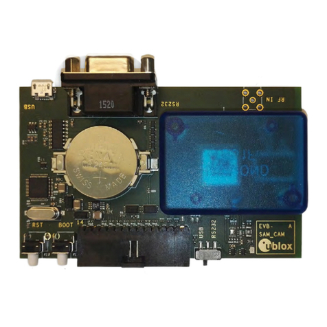
Ublox EVK-M8BZOE User manual

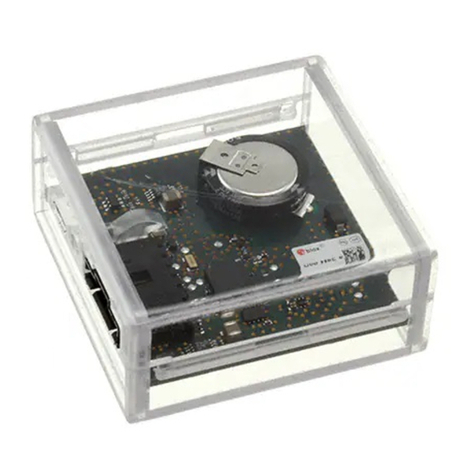
EVK-M8BZOE - User Guide
UBX-17053592 - R03 Early Production Information Page 2 of 33
Document Information
Title EVK-M8BZOE
Subtitle Evaluation Kit
Document type User Guide
Document number UBX-17053592
Revision and Date R03 23-Feb-2018
Document status Early Production Information
Document status explanation
Objective Specification Document contains target values. Revised and supplementary data will be published later.
Advance Information Document contains data based on early testing. Revised and supplementary data will be published later.
Early Production Information Document contains data from product verification. Revised and supplementary data may be published
later.
Production Information Document contains the final product specification.
European Union regulatory compliance
EVK-M8BZOE complies with all relevant requirements for RED 2014/53/EU. The EVK-M8BZOE Declaration of Conformity (DoC) is available at
www.u-blox.com within Support --> Product Resources --> Conformity Declaration.
This document applies to the following products:
Product name Type number Hardware Version ROM/FLASH version PCN reference
EVK-M8BZOE EVK-M8BZOE-0-00 C ROM SPG 3.51 N/A
u-blox reserves all rights to this document and the information contained herein. Products, names, logos and designs described herein may
in whole or in part be subject to intellectual property rights. Reproduction, use, modification or disclosure to third parties of this document
or any part thereof without the express permission of u-blox is strictly prohibited.
The information contained herein is provided “as is” and u-blox assumes no liability for the use of the information. No warranty, either
express or implied, is given, including but not limited, with respect to the accuracy, correctness, reliability and fitness for a particular purpose
of the information. This document may be revised by u-blox at any time. For most recent documents, visit www.u-blox.com.
Copyright © 2018, u-blox AG.
u-blox is a registered trademark of u-blox Holding AG in the EU and other countries.

EVK-M8BZOE User Guide
UBX-17053592 - R03Early Production Information Preface
Page 3 of 33
Preface
Using this guide
This guide assumes, the user has basic computer skills and is familiar with the Windows Graphical User Interface
(GUI) and GNSS receiver environments.
The following symbols are used in the document to highlight information:
An index finger points out key information pertaining to device operation and performance.
Warnings and certifications
EVK-M8BZOE is an Electrostatic Sensitive Device (ESD).
CAUTION! RISK OF SHORT CIRCUIT OF THE BATTERY WHEN TOUCHING IT WITH
CONDUCTING PARTS. IN THE UNLIKELY EVENT OF A FAILURE IN THE INTERNAL
PROTECTION CIRCUITRY THERE IS A RISK OF AN EXPLOSION WHEN CHARGING
FULLY OR PARTIALLY DISCHARGED BATTERIES. REPLACE THE BATTERY IF IT NO
LONGER HAS SUFFICIENT CHARGE FOR UNIT OPERATION. CONTROL THE BATTERY
BEFORE USING IF THE DEVICE HAS NOT BEEN OPERATED FOR AN EXTENDED PERIOD
OF TIME.
Products marked with this lead-free symbol on the product label comply with the “Directive
2002/95/EC and Directive 2011/65/EU of the European Parliament and the Council on the
Restriction of Use of certain Hazardous Substances in Electrical and Electronic Equipment”
(RoHS).
EVK-M8BZOE evaluation kit is RoHS compliant.

EVK-M8BZOE User Guide
UBX-17053592 - R03 Early Production Information Contents
Page 4 of 33
Contents
Preface ................................................................................................................................3
Using this guide............................................................................................................................................... 3
Warnings and certifications ............................................................................................................................. 3
Contents..............................................................................................................................4
1Product description ......................................................................................................6
1.1 Overview .............................................................................................................................................. 6
1.1.1 Evaluation kit versions ................................................................................................................... 6
1.1.2 Features ........................................................................................................................................ 6
1.2 Kit includes........................................................................................................................................... 6
1.3 Software and documentation ............................................................................................................... 7
1.4 u-center GNSS evaluation software....................................................................................................... 7
1.5 System requirements ............................................................................................................................ 7
2Specifications................................................................................................................8
2.1 Safety precautions ................................................................................................................................ 8
3Getting Started.............................................................................................................9
3.1 Software installation ............................................................................................................................. 9
3.2 Hardware installation............................................................................................................................ 9
3.3 Interface default configuration ........................................................................................................... 10
4Device description......................................................................................................11
4.1 Power supply ...................................................................................................................................... 11
4.1.1 5V main power supply................................................................................................................. 11
4.1.2 Backup power supply .................................................................................................................. 11
4.2 Interfaces............................................................................................................................................ 11
4.2.1 Interface Switch........................................................................................................................... 11
4.2.2 USB 2.0 micro connector............................................................................................................. 11
4.2.3 RS-232 connector........................................................................................................................ 12
4.2.4 UART........................................................................................................................................... 12
4.2.5 SPI............................................................................................................................................... 12
4.2.6 DDC (I²C) .................................................................................................................................... 12
4.3 GNSS signal inputs.............................................................................................................................. 12
4.3.1 Active antenna input ................................................................................................................... 14
4.3.1 Simulator input............................................................................................................................ 14
4.4 Digital Connector ............................................................................................................................... 14
4.5 Flash................................................................................................................................................... 15
4.6 RESET_N and SAFEBOOT_N ................................................................................................................ 15
4.7EXTINT................................................................................................................................................ 15
5Testing Super-E mode ................................................................................................16

EVK-M8BZOE User Guide
UBX-17053592 - R03 Early Production Information Contents
Page 5 of 33
5.1 Power Mode Setup message UBX-CFG-PMS ....................................................................................... 16
5.2 Extended Power Management message UBX-CFG-PM2...................................................................... 16
5.3 Other useful messages........................................................................................................................ 18
6Measuring current consumption ...............................................................................20
6.1 Basic measurements with the shunt resistors ...................................................................................... 20
6.1.1 ZOE-M8B VCC current ................................................................................................................ 21
6.1.2 ZOE-M8B V_BCKP current ........................................................................................................... 22
6.1.3 ZOE-M8B optional Flash and logic current ................................................................................... 22
6.2 Measurement with an external current measuring power supply ........................................................ 23
7Board assembly ..........................................................................................................24
8Schematic....................................................................................................................27
9Troubleshooting .........................................................................................................29
10 Common evaluation pitfalls ......................................................................................31
Related documents...........................................................................................................32
Revision history................................................................................................................32
Contact..............................................................................................................................33

EVK-M8BZOE User Guide
UBX-17053592 - R03 Early Production Information Product description
Page 6 of 33
1Product description
1.1 Overview
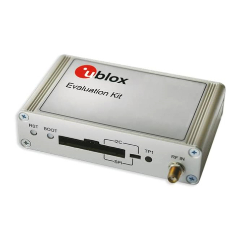
The EVK-M8BZOE evaluation kit simplifies the evaluation of ZOE-M8B, the u-blox ultra small super low power M8
concurrent GNSS S-LGA SiP (System-in-Package). The built-in USB interface provides both power supply and high-
speed data transfer, and eliminates the need for an external power supply. The u-blox evaluation kits are compact,
and their user friendly interface and power supply make them ideally suited for use in laboratories or vehicles.
Furthermore, they can be used with a PDA or a notebook PC, making them the perfect companion through all
stages of design-in projects.
1.1.1 Evaluation kit versions
Evaluation Kit Description Suitable for
EVK-M8BZOE
(PCB version C)
u-blox M8 low power GNSS evaluation kit with ZOE-M8B SiP ZOE-M8B
Table 1: List of available evaluation kit
The version identification of the evaluation kit is printed on the PCB board.
1.1.2 Features
•Supports GNSS performance evaluation with simulator and active antenna
o2 SMA connectors; one for simulator use case, one for external active antenna use case
•Populated optional flash
oConfiguration can be saved permanently
oLogging can be done
oAssistNowTM Offline data can be saved
oOptimal performance of AssistNowTM Autonomous
•Current measurement shunt resistors and corresponding measurement pins
o1 Ωshunt resistor makes it easy to convert measured voltage to actual power consumption
oSet of jumpers to bypass these shunt resistors for more advanced power measurements
•RTC crystal and backup supply to evaluate backup, hot start, and warm start functions
o100 Ωshunt resistor to measure backup power consumption
oSuper capacitor of 1 F for backup supply
•USB 2.0 connector for both power supply and data transfer
oZOE-M8B SiP does not support USB connection. For this reason the EVK-M8BZOE board
contains a separate Silicon Labs CP2102 USB to UART Bridge
•RS-232 DB9 connector and digital connector for easy interfacing with UART, SPI and DDC (I²C) and for
evaluating other advanced scenarios
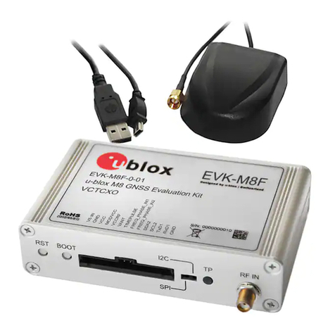
1.2 Kit includes
•EVK-M8BZOE evaluation board
•Active GNSS antenna with a 3 m cable
•USB cable
A plastic cap is attached on the top of the ZOE-M8B GNSS S-LGA SiP in EVK-M8BZOE. The purpose of the
cap is to prevent air flow at ZOE-M8B.

EVK-M8BZOE User Guide
UBX-17053592 - R03 Early Production Information Product description
Page 7 of 33
1.3 Software and documentation
The EVK-M8BZOE installation software and documentation is available at https://www.u-blox.com/en/evaluation-
kits.
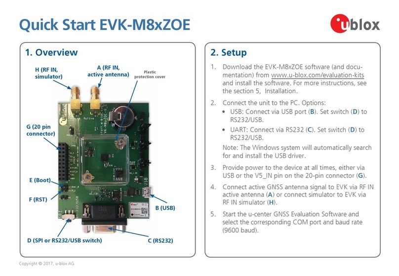
EVK-M8xZOE Quick Start Guide [5] is available at https://start.u-blox.com
u-center GNSS evaluation software and Windows driver for the evaluation board are available from web. See
Section 3.1 for details.
For more ZOE-M8B related documentation, see the ZOE-M8B Data Sheet [1], the ZOE-M8B System Integration
Manual [2] and the u-blox 8 / u-blox M8 Receiver Description including Protocol Specification [3].
1.4 u-center GNSS evaluation software
The installation software includes u-center, which is an interactive tool for configuration, testing, visualization and
data analysis of GNSS receivers. It provides useful assistance during all phases of a system integration project.
1.5 System requirements
•PC with USB or RS-232 interface
•Operating system: Windows 7 onwards (x86 and x64 versions)
•The EVK board includes Silicon Labs CP2102 USB to UART Bridge. Windows drivers for this interface are
available from Microsoft Windows Update service. See section 3.1 for details.

EVK-M8BZOE User Guide
UBX-17053592 - R03 Early Production Information Specifications
Page 8 of 33
2Specifications
Parameter Specification
Serial Interfaces 1 USB V2.0
1 RS232, max. baud rate 460.8 kBd
-DB9: PC compatible
1 DDC (I2C compatible) max. 400 kHz
1 SPI , max. clock 1 MHz, max. data 125 kbytes/second
1 UART , max. baud rate 460.8 kBd
Dimensions 83 x 67 x 20 mm
Power Supply 5 V via micro USB connector or external powered via extra power supply pin 2 (V5_IN)
and pin 18 (GND) on digital connector
Normal Operating temperature -20°C to +70°C
Table 2: EVK-M8BZOE specification
2.1 Safety precautions
EVK-M8BZOE must be supplied by an external limited power source in compliance with the clause 2.5 of the
standard IEC 60950-1. This power source must be a Safety Extra-Low Voltage (SELV) circuit, and only SELV circuits
are to be connected to the evaluation kit interfaces and antennas.
For more information about SELV circuits see section 2.2 in Safety standard IEC 60950-1 [6]

EVK-M8BZOE User Guide
UBX-17053592 - R03 Early Production Information Getting Started
Page 9 of 33
3Getting Started
3.1 Software installation
Installation of the EVK-M8BZOE software and documentation requires internet access.
Download and install the u-center GNSS evaluation software from the u-blox website at
https://www.u-blox.com/en/product/u-center-windows.
Once the zip file is downloaded, unzip it and double-click the extracted exe file. The u-center software will be
installed on your system and placed under the “u-blox” folder in the “Start Programs” menu.
Windows drivers for the Silicon Labs CP210x USB to UART Bridge of the EVK are available from Microsoft Windows
Update service. The Windows system driver search mechanism can download and install the USB drivers
automatically from Microsoft Windows Update service. If the automatic install fails, or if the PC already has an old
version of the drivers installed, the correct version of the driver can be downloaded and installed manually from
Silicon Labs at http://www.silabs.com/products/mcu/pages/usbtouartbridgevcpdrivers.aspx.
Please make sure you select the driver version which does not include “Serial Enumeration” functionality.
3.2 Hardware installation
This section describes the evaluation board connectors and configuration settings that are required to get started.
Figure 1 shows an overview of EVK-M8BZOE board and its connectors.
Figure 1: Getting started overview

EVK-M8BZOE User Guide
UBX-17053592 - R03 Early Production Information Getting Started
Page 10 of 33
1. Make sure the “Interface Switch” is at RS-232 / USB side (and not SPI side).
2. Connect the jumpers J4, J7 and J6 as above (There is a white box drawn around the pins of these jumpers).
3. Connect the evaluation board to a PC by micro USB cable and / or RS-232.
•If a USB cable is used the device is powered by the USB cable.
oA USB connection creates a virtual COM port to the PC.
•If an RS-232 interface is used, the device can be powered by USB cable or by the digital connector
connecting 5 V to pin 2 and GND to pin 18.
4. Connect the active antenna to the “Active” (Active antenna input) or the simulator to the “Passive” input
(Simulator input).
5. Start the u-center GNSS Evaluation Software and select the corresponding COM port and baud rate, 9600
Bd by default (refer to the u-center User Guide [4] for more information).
3.3 Interface default configuration
Parameter Description Remark
RS-232, Input UBX and NMEA protocol at 9’600 Bd
RS-232, Output UBX and NMEA protocol at 9’600 Bd Only NMEA messages are activated by default
USB, Input UBX and NMEA protocol
USB, Output UBX and NMEA protocol Only NMEA messages are activated by default
Table 3: Default configuration
There is also SPI, DDC and UART interface available for debugging and design-in purposes on the digital
connector J1.

EVK-M8BZOE User Guide
UBX-17053592 - R03 Early Production Information Device description
Page 11 of 33
4Device description
4.1 Power supply
4.1.1 5V main power supply
The EVK-M8BZOE board must be supplied either by the micro USB connector or by an external 4.5 V – 5.5 V power
supply connected to digital connector pin 2 and GND to pin 18, see Figure 1.
The interface circuitry and other logic on the board relies on the 5 V power supply to always work properly.
In the default setup this 5 V main power supply is connected to the low-dropout linear voltage regulators (LDOs)
that provide the 1.8 V VCC voltage of ZOE-M8B.
Power consumption of a ZOE-M8B based design can however be easily calculated by measuring the voltage drop
over the VCC current measurement shunt resistor and then multiplying the resulting values by the 1.8 V power
supply voltage. For more information about current measurement of ZOE-M8B, see section 6.1.
4.1.2 Backup power supply
The backup supply (V_BCKP) of ZOE-M8B is used to supply the ZOE-M8B and the optional RTC crystal during
hardware backup mode (main supply removed). This enables hot start and warm start capabilities.
The EVK-M8BZOE includes a super capacitor to supply the V_BCKP of ZOE-M8B.
In normal operation, when the main supply of ZOE-M8B (VCC) is present, the backup domain in ZOE-M8B is
supplied by the main supply. V_BCKPsupplies the backup domain of ZOE-M8B only when the main supply VCC
is removed.
4.1.2.1 Super Capacitor
The capacity of the super capacitor is 1 F and provides backup power over a 100 Ωshunt resistor to the ZOE-M8B
(V_BCKP). When this 1 F capacitor is fully charged to 3.3 V, it can provide backup power for about 35 hours
(t=C*U/I=1*(3.3-1.4)/15uA=126’666 sec. -> ~35 hours).
As soon as the EVK-M8BZOE is supplied, the super capacitor gets charged.
When evaluating very long backup periods, the backup supply can be supplied by the digital connector J1 pin 1
(2.5 V…3.6 V).
4.2 Interfaces
The EVK-M8BZOE supports all three communication interfaces of ZOE-M8B: UART, DDC(I2C) and SPI. The ZOE-M8B
SiP itself does not have a USB interface. There is a USB to UART converter on EVK-M8BZOE which allows
communication to ZOE-M8B by USB.
The UART interface of ZOE-M8B is available on USB, RS232 and on digital connector J1. Only use one of them to
communicate. The SPI and the DDC (I2C) interface are only supported on digital connector J1, see section 4.4.
4.2.1 Interface Switch
The Interface Switch has to be set according if either the UART (RS232/USB) and DDC (I²C) or the SPI interface is
used. See Figure 1 for location of interface switch.
Only if SPI communication interface on digital connector is used, the interface switch has to be switched to
SPI marking. For all other communication interfaces it has to be set at RS-232 / USB marking.
4.2.2 USB 2.0 micro connector
The USB 2.0 micro B connector on the evaluation board can be used for both power supply and communication.
On the EVK-M8BZOE there is a USB to UART converter to UART interface of ZOE-M8B.
The easiest way to evaluate the EVK-M8BZOE operation is to connect the board to a PC by a micro USB cable and
then to use the u-center to configure and monitor the GNSS function.

EVK-M8BZOE User Guide
UBX-17053592 - R03 Early Production Information Device description
Page 12 of 33
When the board is connected to the PC, Windows creates a virtual COM port to the PC. This newly created virtual
COM port needs then to be selected on the u-center application.
The UART communication speed is by default set to 9’600 Bd. Speeds up to 460’800 Bd are supported by ZOE-
M8B.
4.2.3 RS-232 connector
The RS-232 serial port interface can be used to connect the EVK-M8BZOE board to a PC or to other evaluation
host system.
Connect using a straight RS-232 serial cable with male and female connectors. The maximum cable length is 3
meters. To configure the RS-232 port, use the CFG-PRT command in the u-center application. The maximum
supported operating baud rate is 460’800 Bd. 8 data bits, 1 stop bit, and no parity is used. Neither handshaking
signals nor hardware flow control signals are available. The serial port operates in asynchronous mode.
The 9-pin D-SUB female connector is assigned as listed in Table 4.
Pin Nr. Assignment Remarks
1, 7
Timepulse
Not supported by ZOE-M8B firmware.
4 EXTINT0 Can be used for aiding purposes
2 TXD, GNSS Transmit Data, serial data to EVK
3 RXD, GNSS Receive Data, serial data from EVK
5 GND
6, 8, 9 not connected
Table 4: SUB-D9 Connector pin description for EVK-M8BZOE
If the RS-232 interface is used, the device must be powered either by USB cable or by the digital connector J1
connecting 5V to pin 2 and GND to pin 18.
The UART communication speed is by default set to 9’600 Bd. Speeds up to 460’800 Bd can be used if the host
PC system can reliably support those. Please note that the RS232 of many PCs can only support up to 115’200 Bd.
4.2.4 UART
The UART RX and TX of ZOE-M8B are available on the digital connector J1 with 1.8 V levels, see section 4.4 for
more information. The UART communication speed is by default set to 9’600 Bd. ZOE-M8B SiP supports speeds
up to 460’800 Bd.
4.2.5 SPI
The SPI interface pins are available on digital connector J1, see section 4.4 for more information.
If using SPI interface, the slide switch has to be set accordingly.
4.2.6 DDC (I²C)
The digital connector J1 contains pins for evaluating DDC (I²C) bus communication. For such evaluation the
interface switch must be in correct position: RS-232 / USB.
Additional pull-ups on DDC lines to 1.8 V can be installed on the EVK-M8BZOE if needed, see R4 and R6 in Figure
14.
4.3 GNSS signal inputs
The EVK-M8BZOE has two RF inputs for GNSS signals. The purpose is to have optimal performance for “no gain”
and for “high gain” use cases, that is, for passive antenna designs and active antenna designs.

EVK-M8BZOE User Guide
UBX-17053592 - R03 Early Production Information Device description
Page 13 of 33
Figure 2: GNSS signal inputs
Do not use both GNSS inputs at the same time. Either use the passive (simulator) input or use the active
antenna input.
Figure 3: EVK-M8BZOE schematic of GNSS inputs
The RF switch (U14) allows only one of the two GNSS signal inputs to reach the ZOE-M8B.

EVK-M8BZOE User Guide
UBX-17053592 - R03 Early Production Information Device description
Page 14 of 33
4.3.1 Active antenna input
The active antenna input provides 3.3 V supply for active antenna. There is a current limiter circuitry which limits
the maximum current to about 50 mA. Beside the current limiter there is also a current detector circuit which has
the threshold at 5 mA. That is how the RF switch (U14) is set if the active antenna Input goes to ZOE-M8B or the
Simulator input.
Only if current drawn at active antenna input is more than 5 mA, it can be used.
4.3.1.1 Direct ZOE-M8B GNSS performance
There is also an option to have the active antenna input available without connecting an active antenna. In that
case jumper J8 has to be populated, see Figure 2 and Figure 3. Having jumper J8 populated ensures a current draw
at active antenna input and thus the RF switch will still stay at the active antenna input.
Thus a passive antenna or simulator can be connected and performance can be verified when there is no external
LNA in front of ZOE-M8B SiP.
There is DC at the active antenna input, so consider to use a DC block.
4.3.1 Simulator input
At Simulator input there is an external LNA (U12) used in front of ZOE-M8B to show optimal GNSS performance.
This allows verifying datasheet values of ZOE-M8B SiP with a GNSS simulator.
Only if NO current is drawn at the active antenna input (< 5 mA), can the simulator input be used. Ensure
no active antenna is connected to the active antenna input and that Jumper J8 is not populated.
4.4 Digital Connector
There is a 20-pin connector on EVK-M8BZOE. It provides several PIO’s, interfaces and supply options. All these pins
are ESD protected.
PIN Nr.
PIN NAME I/O LEVEL DESCRIPTION
1 V_BCKP I 2.5V…3.6V Backup supply
2 V5_IN I 4.5V…5.5V Main Supply
3 NC
4 GND - GND
5 SAFEBOOT_N I 1.8 V
6 GND - GND
7 SDA / SPI CS_N I/O 1.8V DDC SDA or SPI CS_N, depends on interface switch
8 GND - GND
9 SCL / SPI SCK I/O 1.8V DDC SCL or SPI SCK, depends on interface switch
10 GND - GND
11 TIMEPULSE1 O 1.8V Timepulse not supported by ZOE-M8B firmware.
12 GND - GND
13 EXTINT0 I 1.8V External input, can be used for time aiding.
14 GND - GND
15 RESET_N I 1.8V RESET input
16 GND - GND
17 TXD / SPI MISO O 1.8 V UART TX or SPI MISO, depends on interface switch
18 GND - GND
19 RXD / SPI MOSI I 1.8 V UART RX or SPI MOSI, depends on interface switch
20 GND - - GND
Table 5: Connector pin description for EVK-M8BZOE

EVK-M8BZOE User Guide
UBX-17053592 - R03 Early Production Information Device description
Page 15 of 33
4.5 Flash
EVK-M8BZOE has an SQI flash connected to ZOE-M8B SiP. By default it can be used to:
•Store the current configuration permanently
•Save data logging results
•Hold AssistNowTM Offline and AssistNowTM Autonomous data
4.6 RESET_N and SAFEBOOT_N
RESET_N and SAFEBOOT_N are available on jumpers (J5 and J10) as well as on digital connector J1, see section
4.4 for more information.
4.7 EXTINT
On the EVK-M8BZOE the EXTINT signal of ZOE-M8B is available on digital connector J1 (see section 4.4), and on
RS-232 connector (see section 4.2.3).
If EXTINT0 on RS-232 is used, ensure the EXTINT signal available at digital connector J1 is connected to
1.8 V.

EVK-M8BZOE User Guide
UBX-17053592 - R03 Early Production Information Testing Super-E mode
Page 16 of 33
5Testing Super-E mode
This section contains a brief description of main configuration options for optimizing Super-E mode performance
and power consumption using the Messages view of the u-center evaluation software. Refer to the ZOE-M8B Data
Sheet [1], ZOE-M8B System Integration Manual [2] and u-blox 8 / u-blox M8 Receiver Description including Protocol
Specification [3] for full descriptions of all available configuration options.
5.1 Power Mode Setup message UBX-CFG-PMS
Power Mode Setup message UBX-CFG-PMS shown in Figure 4 is used to select the power mode. Continuous or
Super-E mode can be selected. There are three predefined power mode setups for Super-E mode including 1 Hz
(default), 2 Hz and 4 Hz update rates. The 1 Hz update rate is a good compromise between position accuracy vs.
power consumption. For demanding applications, 2 Hz update rate provides high performance at some
compromise in power consumption.
For lowest power consumption, Super-E mode supports continuous tracking with update periods up to 10 s. To
set update periods longer than 1 s, select default Super-E mode (1 Hz) and use Extended Power Management
message UBX-CFG-PM2 to set the update period.
u-blox recommends using the predefined power mode settings for Super-E mode, except where users have
very specific power saving requirements.
When selecting a mode using CFG-PMS, always save the configuration by checking the “save
configuration” box in u-center, otherwise the configuration will be lost.
Figure 4: Power Mode Setup message UBX-CFG-PMS. Super-E mode with a desired update rate (1 Hz, 2 Hz or 4 Hz) can be selected
with Options 3(default)-5. Options 0-1 are for Continuous mode settings.
5.2 Extended Power Management message UBX-CFG-PM2
Extended Power Management message UBX-CFG-PM2 shown in Figure 5 offers additional options for Super-E
configuration.
Update periods longer than 1 s are set with the field updatePeriod. The field is automatically set by UBX-CFG-PMS
message for 1-4 Hz update rates, but needs to be adjusted for longer update periods. For example, for 3 s update
period set updatePeriod field to 3000 ms. The maximum value for updatePeriod is 10000 ms , i.e., 10 s.
At start-up, the receiver runs at full power and decodes satellite data (ephemeris, almanac). This initial acquisition
period is by default 300 s to enable receiver to find a sufficient number of satellites also under weak-signal
conditions. If needed, the initial acquisition period can be adjusted with the minAcqTime field given in seconds.
The initial acquisition period can be reduced or even removed if AssistNowTM service is used to provide the satellite
information for the receiver. Use of AssistNowTM improves receiver performance and reduces power consumption
and is strongly recommended with Super-E mode.

EVK-M8BZOE User Guide
UBX-17053592 - R03 Early Production Information Testing Super-E mode
Page 17 of 33
Super-E mode has two settings for power optimization targets. The optimization target is set with optTarget field
and is used with any update rate selected. The “performance” (default) provides an optimum compromise
between position accuracy vs. power consumption. Additional power savings up to 15-20% can be achieved with
the “power save” setting, but at the expense of position accuracy.
Use first UBX-CFG-PMS to select the power mode, followed by UBX-CFG-PM2 to modify the settings if
needed. Sending UBX-CFG-PMS after UBX-CFG-PM2 resets the fields in UBX-CCFG-PM2.
Figure 5: Extended Power Management message UBX-CFG-PM2. Main use is to set update periods longer than 1 s, adjusting initial
acquisition period, and to select the Super-E optTarget. NOTE: u-center v8.29 or later displays the optTarget options correctly.

EVK-M8BZOE User Guide
UBX-17053592 - R03 Early Production Information Testing Super-E mode
Page 18 of 33
5.3 Other useful messages
Super-E mode has three different states: acquisition, tracking, and power-optimized tracking. The power-
optimized tracking state is the low-power state of the Super-E mode. Acquisition and tracking states are used
during initial acquisition phase or in case fix is lost or satellite data for new satellites needs to be decoded. In most
cases, after initial acquisition phase the receiver spends all or most of the time in power-optimized tracking state.
Information on the Super-E state is given in the UBX-NAV-PVT message shown in Figure 6.
The default constellations used by the receiver are GPS, GLONASS and QZSS. The constellations used can be
selected with the UBX-CFG-GNSS message shown in Figure 7. Depending on region, it may be beneficial to
configure the receiver to use GPS, BeiDou and QZSS. Note however that AssistNowTM Offline service currently
supports GPS and GLONASS but not BeiDou. For absolute lowest power consumption, the receiver can be
configured to receive only GPS and QZSS satellites. This may affect the availability of satellites resulting in reduced
performance and is not recommended unless power saving is critical.
Figure 6: Navigation information is found in UBX-NAV-PVT message. In addition to time, position and velocity information, the
message contains a field indicating receiver state. The PSM state “Power optimized tracking” is the low-power state of Super-E
mode.

EVK-M8BZOE User Guide
UBX-17053592 - R03 Early Production Information Testing Super-E mode
Page 19 of 33
Figure 7: Constellations used can be selected with UBX-CFG-GNSS message. For absolute lowest-power applications, current
consumption can be further reduced by disabling GLONASS.

EVK-M8BZOE User Guide
UBX-17053592 - R03 Early Production Information Measuring current consumption
Page 20 of 33
6Measuring current consumption
6.1 Basic measurements with the shunt resistors
Figure 8: EVK-M8BZOE board measuring the ZOE-M8B VCC current
On the EVK-M8BZOE there is a 1.8 V LDO supplying the ZOE-M8B main supply (VCC). At the input of that LDO is
a 1 Ωcurrent measurement shunt resistor placed in between J7 pin 1 and pin 2, see Figure 8.
A super capacitor charged to 3.3 V supplies the V_BCKP for ZOE-M8B. In between the super capacitor and V_BCKP
there is a 100 Ωcurrent measurement shunt resistor placed in between J6 pin 1 and pin 2.
This manual suits for next models
2
Table of contents
Other Ublox Motherboard manuals

Ublox
Ublox EVK-F9DR User manual

Ublox
Ublox C94-M8P User manual

Ublox
Ublox TOBY-R2 Series User manual

Ublox
Ublox XPLR-HPG-2 User manual

Ublox
Ublox C099-F9P User manual

Ublox
Ublox C102-F9R User manual

Ublox
Ublox EVK-M8L User manual

Ublox
Ublox EVK-NINA-W1 User manual

Ublox
Ublox TOBY-L2 series User manual

Ublox
Ublox EVK-ANNA-B112 User manual

Ublox
Ublox EVK-M9DR User manual

Ublox
Ublox EVK-BMD-340 User manual

Ublox
Ublox EVK-M8QSAM User manual

Ublox
Ublox C93-M8E User manual

Ublox
Ublox EVK-U201SARA User manual

Ublox
Ublox EVK-M8CCAM User manual

Ublox
Ublox EVK-R6 User manual

Ublox
Ublox C099-F9P User manual

Ublox
Ublox BMD-34 EVK Series User manual

Ublox
Ublox SARA-R5 Series User manual