Ublox EVK-NINA-B400 User manual

UBX-19054587 - R04
C1 - Public www.u-blox.com
EVK-NINA-B4
Evaluation kit for NINA-B4 modules
User guide
Abstract
This document describes how to set up the EVK-NINA-B4 evaluation kit to evaluate NINA-B4 series
standalone Bluetooth®5.1 low energy modules. It also describes the different options for debugging
and testing the development capabilities included in the evaluation board.

EVK-NINA-B4 - User guide
UBX-19054587 - R04 Document information Page 2 of 40
C1 - Public
Document information
Title
EVK-NINA-B4
Subtitle
Evaluation kit for NINA-B4 modules
Document type
User guide
Document number
UBX-19054587
Revision and date
R04
29-Jun-2021
Disclosure restriction
C1 - Public
This document applies to the following products:
Product name
EVK-NINA-B400
EVK-NINA-B410
EVK-NINA-B410DF
EVK-NINA-B406
EVK-NINA-B416
u-blox or third parties may hold intellectual property rights in the products, names, logos and designs included in this
document. Copying, reproduction, modification or disclosure to third parties of this document or any part thereof is only
permitted with the express written permission of u-blox.
The information contained herein is provided “as is” and u-blox assumes no liability for its use. No warranty, either express or
implied, is given, including but not limited to, with respect to the accuracy, correctness, reliability and fitness for a particular
purpose of the information. This document may be revised by u-blox at any time without notice. For the most recent
documents, visit www.u-blox.com.
Copyright © u-blox AG.

EVK-NINA-B4 - User guide
UBX-19054587 - R04 Contents Page 3 of 40
C1 - Public
Contents
Document information .............................................................................................................................2
Contents .......................................................................................................................................................3
1Quick start guide.................................................................................................................................5
2Product description............................................................................................................................6
2.1 Overview........................................................................................................................................................6
2.2 Kit includes...................................................................................................................................................7
2.3 Key features .................................................................................................................................................7
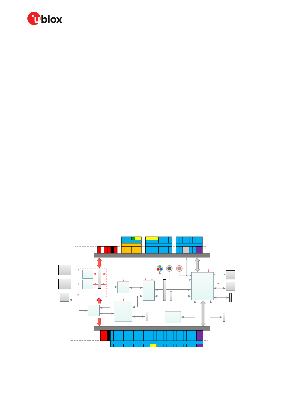
2.4 EVK-NINA-B4 block diagram ....................................................................................................................8
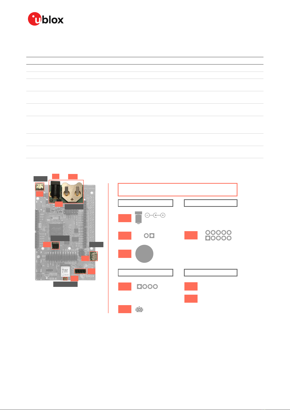
2.5 Connectors ...................................................................................................................................................9
3Setting up the evaluation board .................................................................................................. 10
3.1 Evaluation board setup............................................................................................................................10
3.2 Starting up .................................................................................................................................................10
EVK-NINA-B41x ................................................................................................................................10
EVK-NINA-B40x ................................................................................................................................11
3.3 Measuring current consumption...........................................................................................................11
Using an ampere meter...................................................................................................................11
Using a voltmeter .............................................................................................................................12
Using an external power supply or power analyzer....................................................................13
4Board configuration......................................................................................................................... 14
4.1 Powering options.......................................................................................................................................14
Selecting the power configuration jumpers................................................................................14
Default power configuration, 3.3 V ...............................................................................................17
Battery powered, 3–1.7 V ................................................................................................................18
Battery powered with protection diode, 2.7–1.7 V.....................................................................19
External supply, 3.6–1.7 V...............................................................................................................20
Raspberry Pi HAT..............................................................................................................................21
4.2 Disconnecting NINA signals from board peripherals ........................................................................21
4.3 Connecting an external antenna (EVK-NINA-B410DF).....................................................................23
5Interfaces and peripherals ............................................................................................................ 24
5.1 Buttons and LEDs.....................................................................................................................................24
5.2 Arduino interface ......................................................................................................................................25
Arduino shield compatibility...........................................................................................................27
5.3 Raspberry Pi compatible interface ........................................................................................................27
Powering considerations.................................................................................................................30
UART ...................................................................................................................................................30
EEPROM support..............................................................................................................................30
5.4 Additional Interfaces................................................................................................................................30
Extra memory –external Flash ......................................................................................................32
Extra USB to UART interface .........................................................................................................32
CPU trace interface..........................................................................................................................33

EVK-NINA-B4 - User guide
UBX-19054587 - R04 Contents Page 4 of 40
C1 - Public
Appendix .................................................................................................................................................... 34
ASchematics ........................................................................................................................................ 34
BGlossary .............................................................................................................................................. 38
Related documents ................................................................................................................................ 39
Revision history ....................................................................................................................................... 39
Contact....................................................................................................................................................... 40

EVK-NINA-B4 - User guide
UBX-19054587 - R04 Quick start guide Page 5 of 40
C1 - Public
1Quick start guide
EVK-NINA-B4 software and documentation is available at www.u-blox.com/evk-search.
Install s-center evaluation software
s-center is a powerful and easy-to-use tool for evaluating, configuring, and testing u-blox short range
modules. Running on Windows 10 operating systems, the software allows end users to assess and
configure u-blox short range modules using the EVK.
Follow the procedure outlined below to download and install the s-center software and
documentation. The software can be downloaded from the u-blox s-center product page and is
available free of charge.
1. Download the latest s-center software to your computer.
2. Open the s-center setup installer to install the software.
3. Select Launch button in the installer or open the application from the Windows Start button.
Install J-Link drivers
Follow the procedure outlined below to install the J-Link drivers needed for programming the module.
1. Connect the EVK-NINA-B4 board to your PC using the USB cable provided with the product.
2. Verify that the USB drivers are installed successfully. Check the Evaluation board setup if the
drivers do not install automatically.
3. Once the drivers are installed, a COM port is enabled in Windows. Use the Windows Device
Manager to view the port number (COM #) for the USB serial port.
4. Start s-center to communicate with the module.
For EVK-NINA-B4x0 (with external antenna), attach the antenna to the antenna cable and connect
the antenna cable to the U.FL connector.
⚠The initial prototypes of EVK-NINA-B406, marked with PT1 (date code 1950 or older) have a
different pin out and some hardware limitations. This is described in the sample delivery notes
that come with the prototypes.
⚠For EVK-NINA-B410DF flashing tools and procedures, see also the Indoor direction finding
XPLR-AOA explorer kits user guide [8].

EVK-NINA-B4 - User guide
UBX-19054587 - R04 Product description Page 6 of 40
C1 - Public
2Product description
2.1 Overview
The u-blox EVK-NINA-B4 evaluation kit is a versatile development platform that allows quick
prototyping of a variety of extremely low-powered Internet of Things (IoT) applications, using full
Bluetooth 5.1, NFC, and IEEE 802.15.4.
EVK-NINA-B4 boards are available in the following four variants that accommodate alternative
antenna and software solutions:
•EVK-NINA-B400, with open CPU NINA-B400 module and U.FL antenna connector for connecting
to external antennas. The EVK-NINA-B400 is also used for evaluation of NINA-B401 module.
•EVK-NINA-B410, with u-connect NINA-B410 module pre-flashed with u-connectXpress software
or boot prepared for u-connectLocate software (EVK-NINA-B410DF), and U.FL antenna
connector for connecting to external antennas. The EVK-NINA-B410 version is also used for
evaluation of NINA-B411 module.
•EVK-NINA-B406, with open CPU NINA-B406 module that includes an internal PCB trace antenna.
•EVK-NINA-B416, with u-connect NINA-B416 module pre-flashed with u-connectXpress software
and an internal PCB trace antenna.
Figure 1: EVK-NINA-B400/B410 evaluation board

EVK-NINA-B4 - User guide
UBX-19054587 - R04 Product description Page 7 of 40
C1 - Public
Figure 2: EVK-NINA-B406/B416 evaluation board
All NINA-B4 standalone modules include an Arm®Cortex®-M4F microcontroller with a 64 MHz system
clock, 512kB internal flash and 128 kB RAM.
EVK-NINA-B4 evaluation boards provide access to the 38 GPIO pins and interfaces that are supported
on NINA-B4 modules. The interfaces are available through a variety of connectors, including Arduino™
Uno R3 [1] and Raspberry Pi [2] header connectors. The boards alos provide simple USB drag-n-drop
programming and a SEGGER J-Link debug interface that can be used with the Open CPU variants of
the EVK.
Nordic Semiconductors, the manufacturer of the nRF52833 SoC, provide a free Software
Development Kit (SDK) that includes a broad selection of drivers, libraries, and example applications
that can be used for rapid prototyping.
2.2 Kit includes
The EVK-NINA-B4 evaluation kit includes the following:
•NINA-B4 evaluation board
•2.4 GHz antenna with U.FL connector (only in EVK-NINA-B400 and EVK-NINA-B410)
•NFC antenna
•USB cable
2.3 Key features
•u-blox NINA-B4 Bluetooth Low Energy module based on the Nordic nRF52833 SoC
oFull Bluetooth 5.1 support
oNFC tag functionality
o802.15.4 PHY
oIntegrated Arm Cortex-M4 microcontroller with 512kB internal flash and 128 kB RAM, and
64 MHz system clock
oUSB 2.0
oWide 1.7-3.6 V supply range
•The NINA-B4 module supports different interfaces that can be configured to any of the 38
available GPIO pin(s):
o8 analog capable inputs
o16 PWM capable outputs
o4x SPI

EVK-NINA-B4 - User guide
UBX-19054587 - R04 Product description Page 8 of 40
C1 - Public
o2x UART with HW flow control
o2x I2C
o1x I2S
o1x PDM input
o1x Quadrature decoder
•EVK-NINA-B41x: support for u-connectXpress software
•EVK-NINA-B40x: support for developing your own software on the Open CPU NINA-B4 module
•Full UART to USB converter with a Virtual COM port, allowing control of the extended UART
features of the u-connectXpress software
•On-board J-Link debugger/programmer
oMass Storage Device interface to PC, for drag-n-drop programming
oDebug port
oAn additional Virtual COM port that, for example, may be connected to add-on boards or to a
debug UART on the NINA-B4
•Dedicated USB connector for the NINA-B4 USB interface
•Additional flash memory can be added to the board for use by the NINA-B4 module
•RGB LED and push-buttons
•Arduino UNO R3 and Raspberry Pi compatible pin header interfaces
•Jumper headers and level shifters allow for flexible powering options of the NINA-B4 module,
even with full board support. They isolate the module entirely and control each power net
separately to precisely measure low power applications or disconnect only unused parts of the
board to save battery life.
•Multiple board power supply options
o5–12 V power plug
o5 V USB supply
o5–12 V Arduino VIN input
•Battery holder supporting CR2032 coin cell batteries
2.4 EVK-NINA-B4 block diagram
Figure 3 shows the major interfaces and internal connections of the EVK-NINA-B4.
Figure 3: EVK-NINA-B4 block diagram
UART
to USB
USB
conn.
Interface
MCU
(Program &
Debug Unit)
USB
Hub
USB
conn.
Batt.
holder
Power
plug
RF
conn.
Voltage
Level
Shifters
UART
SWD
Flash
Memory
3.3 V VDD_NINA
DC/DC
reg.
Protect.
diodes
NFC antenna
connector
Dedicated NINA
USB 2.0 conn.
VDD_NINA
Bluetooth
802.15.4
Arduino Uno R3 interface
D0
D1
D2
D3
D4
D5
D6
D7
D8
D9
D10
D11
D12
D13
SCL
SDA
A0
A1
A2
A3
A4
A5
IOREF
3V3
5V
VIN
GND
RESET
ADC/Comp. GPIO/Dig. Interface GPIO/Dig. Interface
UART
GPIO/Dig. Int.
UART
SW2
Raspberry Pi 40 pin GPIO header
3V3
5V
GND
GPIO/Digital Interface
UART
ID_SC
ID_SD
RPi_3
RPi_4
RPi_5
RPi_6
RPi_7
RPi_2
RPi_8
RPi_9
RPi_10
RPi_11
RPi_12
RPi_13
RPi_14
RPi_15
RPi_16
RPi_17
RPi_18
RPi_19
RPi_20
RPi_21
RPi_22
RPi_23
RPi_24
RPi_25
RPi_26
RPi_27
NINA
Module
User
RGB LED
User
buttons
Reset
button
NINA
SWD conn.
NINA signal
jumper header
SWD
UART
UART
COM port
pin header
Power selector
jumper headers
USB USB
USB
3.3 V
3.3 V
SPI
20-pin Trace
connector
ETM/ITM
Trace
USB
NFC
RF
VBUS
VBUS
CR2032
3 V
5 - 12 V
NINA COM port
NINA program & debug
Additional COM port
1.7 - 3.6 V
Raspberry Pi pin
NINA Open CPU function
Arduino pin
NINA Connectivity Software function
D10 and D11
are optional

EVK-NINA-B4 - User guide
UBX-19054587 - R04 Product description Page 9 of 40
C1 - Public
2.5 Connectors
Table 1 describes the available connectors of the EVK-NINA-B4 shown in Figure 4.
Connector
Function
Description
J5
Power supply
2.1 mm power jack, the center pin is the positive terminal. 5 –12 V input.
J17
Power supply
Pin header that can be used to connect external power supplies. 5 –12 V input.
BT1
Battery holder
CR2032 coin cell battery holder. CR2032 usually has a 3 V potential when fully
charged.
J11
NFC antenna connector
Pin header that connects to the u-blox NFC antenna included in the kit. The antenna
can be mounted in either direction.
(J2)
2.4 GHz RF antenna
connector
U.FL coaxial connector that can be used to connect antennas or RF equipment. This
connector is only included in the EVK-NINA-B400/EVK-NINA-B410.
J12
Cortex Debug connector
10-pin, 50 mil pitch connector that can be used to connect external debuggers to the
NINA-B4 module. The NINA-B4 modules support Serial Wire debug (SWD) and Serial
Wire Viewer, but not JTAG debug.
J8
Power supply, COM port
and debug USB
The main USB connector that is used to program, debug, and communicate with the
NINA module. It can also be used to power the entire board.
J16
Power supply and NINA
USB port
Additional USB connector directly connected to the NINA-B4 USB interface. Can also
be used to power the entire board.
Table 1: EVK-NINA-B4 connector description
Figure 4: Available connectors and their pinout
J5
21
1 4
GNDVIN
5 - 12 V
NFC1
GND
GND
NFC2
U.FL RF coax, (J2 is the module designator)
GND
GND
N/C
VDD_IO
GND
SWDIO
SWDCLK
GPIO_8
N/C
RESET_N
BT1
J17
Power
J8
J16
USB
Debug
J12
Antennas
J11
(J2)
CR2032
+
3V
2
1
10
9
Micro USB
Micro USB
J17
Debug
Power
Antennas
USB
USB
J8
J5 BT1
J12
J16
(J2)
J11
Board Connectors

EVK-NINA-B4 - User guide
UBX-19054587 - R04 Setting up the evaluation board Page 10 of 40
C1 - Public
3Setting up the evaluation board
3.1 Evaluation board setup
EVK-NINA-B410 and EVK-NINA-B416 boards are delivered with pre-installed u-connectXpress
software. EVK-NINA-B410DF is delivered with a pre-installed boot for download of u-connectLocate
software.
Before connecting the evaluation board, download and install the latest u-blox s-center evaluation
software from the u-blox website.
To use Bluetooth Low Energy on EVK-NINA-B410 and EVK-NINA-B416 boards, connect a 2.4 GHz
antenna to the U.FL antenna connector. The EVK-NINA-B400 and EVK-NINA-B406 board variants
include antennas on the NINA module.
Plug in either an external power supply in the J5 connector or connect to a USB host with a USB cable
attached to the J8 connector. You can also power the evaluation board with a CR2032 coin cell
battery. The NFC antenna can be connected to the J11 connector.
☞Make sure that the power configuration jumpers are connected according to your use case, as
described in Powering options. The Default power configuration, 3.3 V works for most use cases.
⚠Be careful to check polarity before connecting an external power supply to the EVK-NINA-B4
evaluation board. Center conductor is positive (+) and the ring is negative (-).
The operating system installs the correct drivers automatically. The drivers need only be installed
once when you connect the unit to a new computer.
⚠If the drivers are not installed automatically, download the J-Link driver included in the Nordic
nRF Command Line Tools.
Two COM ports are automatically assigned to the unit by Windows:
•The COM port labelled “USB Serial Port”is used to communicate with the UART interface of the
NINA-B4 module.
•The COM port labelled “JLink CDC UART Port”can be used as an extra USB to the UART
interface. See also Extra USB to UART interface.
Use the following procedure to view the assigned COM ports on Windows 7:
1. Open the Control Panel and select Hardware and Sound.
2. Open the Device Manager in Devices and Printers. This opens the Device Manager window where
you can view the assigned COM ports.
3. To view the assigned COM ports on Windows 10, right click the Windows Start button and select
Device Manager.
3.2 Starting up
EVK-NINA-B41x
To communicate with the module using AT commands, install and start the s-connect evaluation
software (see Quick start guide), and set the baud rate to 115200, 8N1 with flow control. All available
AT commands are described in the u-connect AT commands manual [5].
To get started with the basic use case set up of the EVK-NINA-B4 with u-blox u-connect software, see
also the u-connectXpress user guide [7].

EVK-NINA-B4 - User guide
UBX-19054587 - R04 Setting up the evaluation board Page 11 of 40
C1 - Public
3.2.1.1 u-connectXpress software
EVK-NINA-B41x is equipped with a NINA-B41x module that runs the u-connectXpress software. The
software is preinstalled on the module.
☞Go to the u-blox support webpage to obtain the latest available software. Instructions on
reflashing the EVK-NINA-B4 can be found in the Software section of the NINA-B4 system
integration manual [4].
3.2.1.2 u-connectLocate software
EVK-NINA-B410DF is equipped with a NINA-B410-40B module that runs the u-connectLocate
software. The software needs to be downloaded to the module. Note that the NINA-B41x-40B
modules are not compatible with u-connectXpress software, only the u-connectLocate software.
☞Go to the u-blox support webpage to obtain the latest available software. Instructions on
flashing the EVK-NINA-B410DF can be found in the Indoor direction finding XPLR-AOA explorer
kits User Guide [8].
EVK-NINA-B40x
3.2.2.1 Nordic Semiconductor SDK
To use the EVK-NINA-B40x together with Nordic Semiconductor SDK it is necessary to:
•Create your own board file
•Adapt the examples in the Nordic Semiconductor SDK to use this board file
For more information about performing these tasks, see the Software section of the NINA-B4
system integration manual [4]. See also the u-blox short range open CPU github repository [9].
3.2.2.2 Software debug options
Use either of the following options to debug software with EVK-NINA-B4:
•Onboard debug solution available through the USB connector
•External debugger connected to J12 connector
An external debugger is useful when powering the evaluation board with a CR2032 coin cell battery,
or through the J5 external power supply connector. It is also useful when the MCU interface has been
disconnected from the NINA-B4 module using the jumpers on the J19 header.
SEGGER J-Link software [6] is necessary to debug with the onboard J-Link hardware on the EVK-
NINA-B4.
3.3 Measuring current consumption
☞Before starting the current consumption measurement, go through Chapter 4 to identify your
chosen power configuration and find out what NINA signals must subsequently be isolated. The
J22 jumper pins 1 and 3 must be removed to measure the current consumption.
Figure 5 shows some suggestions for connecting the various instruments when measuring module
current consumption.
Using an ampere meter
An ampere meter should be connected in series with whatever the power source is and what is being
measured. In this way the current can be measured when the NINA module is supplied from either the
onboard 3.3 V regulator or an external supply.

EVK-NINA-B4 - User guide
UBX-19054587 - R04 Setting up the evaluation board Page 12 of 40
C1 - Public
Using a voltmeter
The EVK board must be modified before module current can be measured with a voltmeter.
To modify the board, solder a low resistance, high tolerance, 0402 sized resistor to the footprint
labeled R6. This resistor replaces the jumper normally positioned between J22 pins - 1 and 3, and any
current running through it produce a voltage across its terminals. Measure this voltage with the
voltmeter and calculate the current using Ohm’s law.

EVK-NINA-B4 - User guide
UBX-19054587 - R04 Setting up the evaluation board Page 13 of 40
C1 - Public
Using an external power supply or power analyzer
Connect the terminals of the instrument to the EVK pins, as shown in Figure 5. An ampere meter can
also be added in series.
Since the external voltage of any connected instrument can never perfectly match the 3.3 V
generated by the EVK, some small current leakage is apparent whenever the signal from the NINA
module is connected to an EVK peripheral. The leakage is typically in the order of 100’s of nano amps.
To reduce leakage current, use a second external power channel to supply the EVK peripherals. This
second channel must also be used to enable PC communication when using NINA supply voltages
other than 3.3 V.
Figure 5: Different options when measuring the NINA module’s current consumption
J22
VCC_IO
VCC
1
GND
5
AJ22
VCC_IO
VCC
1
GND
5
A
6
4
R6
J22
VCC_IO
VCC
3
1
V
J22
VCC_IO
VCC
3
1
A
Ampere meter Volt meter
One channel Two channels
GND GND
Onboard
3.3 V supply
DC/DC
External supply
1.7 - 3.6 V
-.-- V

EVK-NINA-B4 - User guide
UBX-19054587 - R04 Board configuration Page 14 of 40
C1 - Public
4Board configuration
4.1 Powering options
Power can be supplied to the board in any of the following ways:
•Via any of the USB connectors, J8 or J16
•Using the power jack, J5
•Using the Arduino interface VIN or 5V pin, J1.8 or J1.5
•Using the Raspberry Pi interface 5V pins, J14.2 or J14.4
•Using the pin header J17
•Plugging in a battery to the battery holder BT1
These power supply sources are distributed to the rest of the board as shown in Figure 6.
Figure 6: Block diagram of the power net distribution
Selecting the power configuration jumpers
EVK-NINA-B4 offers flexible powering options for the NINA-B4 module and the board itself. To
configure this, jumpers are added or removed to pin headers, shorting two of the pins together and
connecting or disconnecting different power nets on the evaluation board. Figure 7 shows an overview
of the available power sources and targets. Figure 8 shows the location of the power configuration
jumper headers.
⚠Check the jumper positions carefully. If any jumper is connected in a wrong way, it can
permanently damage the components that are ON or connected to the board. Note also that
some jumpers should not be mounted simultaneously.
Diode protection
3.3 V
DC/DC
Regulator
Fuse
5 V
3.3 V
Diode protection
3 V
2.7 V
J7
Power select
jumper header
J22
NINA power select
jumper header
VDD_NINA
3.3 V
3.3 V
VIN
1.7- 3.6 V
external supply
J1and J14
Arduino and
Raspberry Pi
pin headers
VCC
VCC_IO
VDD_IO
NINA
Module
Board
peripherals
BT1
CR2032
3 V
J5
5 - 12 V
J8
5 V
J16
5 V
J17 pin 2
VIN pin header
5 - 12 V
J1pin 8
Ardunio VIN pin
5 - 12 V
Diode protection
USB
conn.
Batt.
holder
Power
jack
USB
conn.

EVK-NINA-B4 - User guide
UBX-19054587 - R04 Board configuration Page 15 of 40
C1 - Public
Figure 7: Overview of EVK power sources and targets showing connected schematic net names
Figure 8: Jumper headers J7 and J22 board location and pinout
DC/DC
Onboard 3.3 V
converter
Battery
Battery with
protection diode
MCU
PC communication
HAT
Raspberry Pi
expansion board
NINA module power
Board I/O power:
Level shifters, LEDs etc.
3V3
VBAT_DIODE
VBAT
VDD_MCU
3V3_PI
VDD_IO
VCC
VCC_IO
Sources Net names Targets
Any power net
-.-- V
External supply
iguration
GND
GND
VDD_MCU
VDD_NINA
VDD_NINA
VDD_NINA
3V3_PI
3V3
3V3
VBAT
VBAT_DIODE
3V3
J7
J22
111
12 2
J7
GNDGND
VDD_IO
VCC_IO
VDD_NINA
VCC
5
6
21
J22
Power Conf

EVK-NINA-B4 - User guide
UBX-19054587 - R04 Board configuration Page 16 of 40
C1 - Public
Connector
Pin no.
Schematic net
Description
J7
1
3V3
Regulated 3.3 V net. This net is supplied by the board and will always be
powered as long as a power source is connected.
2
3V3_PI
Connects to the Raspberry Pi header’s (J14) 3V3 pins. If a Raspberry Pi is
connected, this net must be unconnected to prevent back currents. If a HAT is
connected, this net can be shorted to the EVK 3.3 V supply to power the HAT.
3
VBAT_DIODE
To protect the battery from current back surges, connect the battery to the
NINA module via a protection diode using this pin.
4
VDD_NINA
Connects to J22 pin 3, from where it can be connected to the module supply
pin or somewhere else.
5
VBAT
Battery + terminal
6
VDD_NINA
Connects to J22 pin 3, from where it can be connected to the module supply
pin or somewhere else.
7
3V3
Regulated 3.3 V net. This net is supplied by the board and will always be
powered as long as a power source is connected.
8
VDD_NINA
Connects to J22 pin 3, from where it can be connected to the module supply
pin or somewhere else.
9
3V3
Regulated 3.3 V net. This net is supplied by the board and will always be
powered as long as a power source is connected.
10
VDD_MCU
Supply net for the board functions not directly connected to the NINA module;
Interface MCU, USB hub, UART to USB converter etc.
11
GND
Ground net
12
GND
Ground net
J22
1
VCC
NINA module voltage supply that connects to the module VCC pin. Shorted to
the VCC_IO net via 0 Ωresistor R4 by default.
2
VCC_IO
Connects to the NINA module VCC_IO pin. Shorted to the VCC net via 0 Ω
resistor R4 by default.
3
VDD_NINA
Connects to J7 pins 4, 6 and 8. Short J22 pins 1 and 3 allow the EVK to power
the NINA module.
4
VDD_IO
Supply net for level shifters, LEDs and peripherals connected directly to the
NINA module. Short J22 pins 2 and 4 use the NINA module I/O voltage as
supply.
5
GND
Ground net
6
GND
Ground net
Table 2: Pinout of jumper headers J7 and J22 used to configure the board power nets

EVK-NINA-B4 - User guide
UBX-19054587 - R04 Board configuration Page 17 of 40
C1 - Public
Default power configuration, 3.3 V
This is the default power configuration for the evaluation board, and the jumpers are installed
out-of-the-box with this power configuration. All board peripherals are powered up, the NINA module
is directly supplied by the board, and everything is running at 3.3 V.
Figure 9: Jumper positions for default power configuration
Connector
Add jumper to pins
Description
J7
7, 8
Selects the board regulated 3.3 V net as source for the VDD_NINA net.
9, 10
Powers up the Interface MCU, USB hub, and UART to USB converter with 3.3 V.
J22
1, 3
Powers up the NINA module. The NINA VCC and VCC_IO pins are connected to the
selected source for the VDD_NINA net.
2, 4
Powers up the peripherals directly connected to NINA such as LEDs and external
memory with the NINA supply voltage.
Table 3: Jumper positions for default power configuration
J7
BOARD
NINA
3V3
34
2 1
J22
VCC_IO
VCC
7
8
9
10
NINA module powerboard I/O power
J22: 2-4 J22: 1-3
PC communication
MCU
DC/DC
EVB powered
J7: 9-10J7: 7-8

EVK-NINA-B4 - User guide
UBX-19054587 - R04 Board configuration Page 18 of 40
C1 - Public
Battery powered, 3–1.7 V
When using a battery, Figure 10 shows the default configuration. The battery voltage is connected to
VDD_NINA, which in turn, is connected to the NINA-B4 VCC supply. If needed, a jumper can be added
to J22 pins - 2 and 4 to supply LEDs and other peripherals with power, as long as this does not exceed
the maximum current rating of the battery. If the NINA module has to be configured, the VDD_MCU
net can be connected to enable PC communications by adding a jumper to J7 pins 9 and 10.
☞Jumpers must be connected to both J7: 9–10 and J22: 2–4 to be able to communicate with the
NINA module from a PC. If possible, the EVB power configuration should be switched to the
default 3.3 V configuration, as connecting an extra board peripheral might deplete the battery.
⚠Do not connect jumpers J7: 5–6 and J7: 7–8 at the same time while a battery is connected. This
might cause damage to the battery.
Figure 10: Jumper positions for battery powered operation, the jumpers shown in dashed lines are optional
Connector
Add jumper to pins
Description
J7
5, 6
Selects the battery connected to the battery holder as source for the VDD_NINA net.
9, 10
(Optional) Powers up the Interface MCU, USB hub, and UART to USB converter with 3.3 V.
J22
1, 3
Powers up the NINA module. The NINA VCC and VCC_IO pins are connected to the
selected source for the VDD_NINA net.
2, 4
(Optional) Powers up the peripherals directly connected to NINA such as LEDs and
external memory with the NINA supply voltage.
Table 4: Jumper positions for battery powered operation, two jumpers are optional
J7
BOARD
BATT
3V3
34
2 1
J22
VCC_IO
VCC
5
6
9
10
NINA module powerboard I/O power
(optional)
J22: 2-4 J22: 1-3
PC communication
(optional)
MCU
J7: 9-10
Battery powered
J7: 5-6

EVK-NINA-B4 - User guide
UBX-19054587 - R04 Board configuration Page 19 of 40
C1 - Public
Battery powered with protection diode, 2.7–1.7 V
This use case is meant to protect the battery from current back surges. When using the NFC
interface, there is a risk that the applied electromagnetic field can cause back surges on the module’s
power supply lines that will typically damage a non-chargeable battery. To prevent this damage, a
Schottky diode is added in series to the battery, which will block any back current surges. A jumper
should be added to J7 pins 3 and 4 instead of 5 and 6.
☞The diode will lower the voltage level of the battery by about 0.3 V.
Figure 11: Jumper positions for battery powered operation with a protection diode (dashed lines show optional jumpers)
Connector
Add jumper to pins
Description
J7
3, 4
Selects the diode protected battery as a source for the VDD_NINA net.
9, 10
(Optional) Powers up the Interface MCU, USB hub, and UART to USB converter with 3.3 V.
J22
1, 3
Powers up the NINA module. The NINA VCC and VCC_IO pins are connected to the
selected source for the VDD_NINA net.
2, 4
(Optional) Powers up the peripherals directly connected to NINA such as LEDs and
external memory with the NINA supply voltage.
Table 5: Jumper positions for battery powered operation with a protection diode (with two optional jumpers)
J7
BOARD
BATT DIODE
3V3
34
2 1
J22
VCC_IO
VCC
3
4
9
10
NINA module powerboard I/O power
(optional)
J22: 2-4 J22: 1-3
PC communication
(optional)
MCU
J7: 9-10J7: 3-4
Battery powered
with protection

EVK-NINA-B4 - User guide
UBX-19054587 - R04 Board configuration Page 20 of 40
C1 - Public
External supply, 3.6–1.7 V
When measuring current consumption or performing other NINA-B4 module characterization
measurements, it can be useful to power the module with an external source such as a lab power
supply. In such cases, all jumpers can be removed and the required supply nets can be fed externally
by connecting to the pin headers. For example, the NINA-B4 module can be powered by connecting an
external supply directly to the J22 pin 1 and GND. See also Using an external power supply or power
analyzer.
☞Make sure that unpowered parts of the board are properly isolated from the NINA module. If a
voltage is applied to the signal of an unpowered device/component, current might leak through
various protection circuits of this device. This might give false readings when measuring current
consumption. Isolation can be achieved by removing NINA signal jumpers. See also
Disconnecting NINA signals from board peripherals.
Figure 12 below shows a few optional jumper connections that can be helpful when supplying the
module with an external supply.
Figure 12: Optional jumper positions while using an external power supply
Connector
Add jumper to pins
Description
J7
7, 8
(Optional) Selects the board regulated 3.3 V net as a source for the VDD_NINA net.
9, 10
(Optional) Powers up the Interface MCU, USB hub, and UART to USB converter with 3.3 V.
J22
3, 4
(Optional) Powers up the peripherals directly connected to NINA such as LEDs and
external memory with the selected source for the VDD_NINA net.
Table 6: Optional jumper positions while using an external supply
J7
BOARD
NINA
3V3
34
J22
7
8
9
10
board I/O power
(optional)
J22: multiple
PC communication
(optional)
MCU
DC/DC
EVB powered
(optional)
J7: 9-10J7: 7-8
VCC_IO
VCC
12
56
GND
-.-- V
External supply
This manual suits for next models
5
Table of contents
Other Ublox Motherboard manuals

Ublox
Ublox EVK-L2 Series User manual

Ublox
Ublox EVK-M10QSAM User manual

Ublox
Ublox EVK-JODY-W3 User manual

Ublox
Ublox EVK-F9DR User manual

Ublox
Ublox EVK-G31 User manual

Ublox
Ublox EVK-M8CCAM User manual

Ublox
Ublox EVK-L4 User manual

Ublox
Ublox EVK-R6 User manual

Ublox
Ublox EVK-M91-00-01 User manual

Ublox
Ublox EVK-ANNA-B112 User manual

Ublox
Ublox EVK-M101 User manual

Ublox
Ublox EVK-M8GZOE User manual

Ublox
Ublox SARA-R5 Series User manual

Ublox
Ublox EVK-M8 User manual

Ublox
Ublox EVK-L2 Series User manual

Ublox
Ublox EVK-U2X User manual

Ublox
Ublox TOBY-L2 series User manual

Ublox
Ublox EVK-M8GZOE User manual

Ublox
Ublox EVK-ANNA-B112 User manual

Ublox
Ublox XPLR-HPG-1 User manual