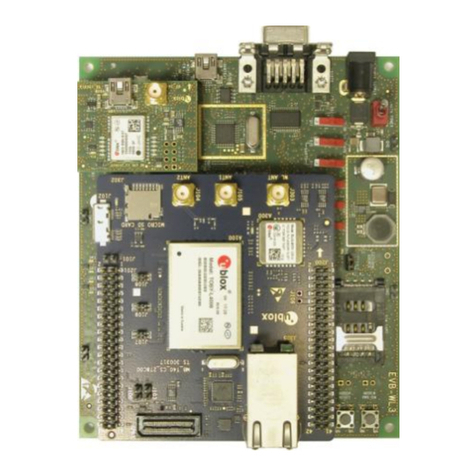
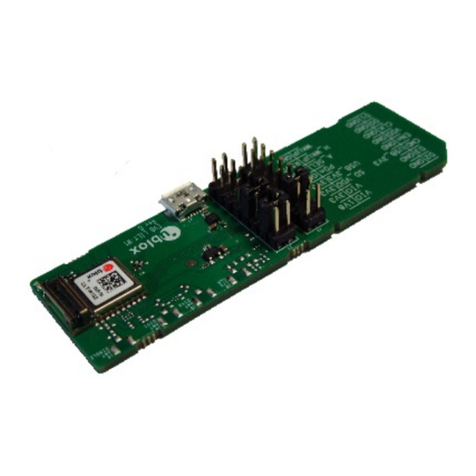
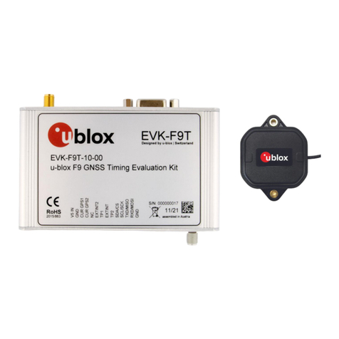
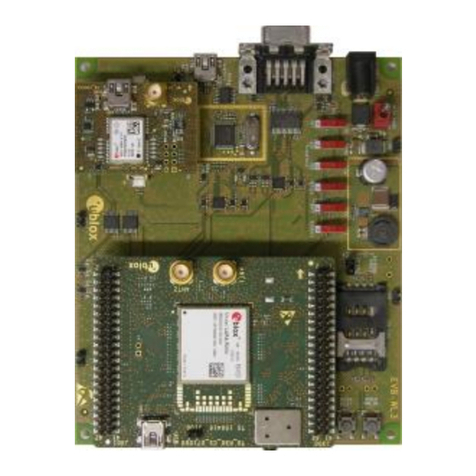
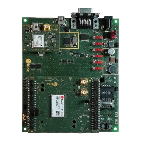
Figure 2: Block diagram of EVK-N3 for SARA-N3 series modules
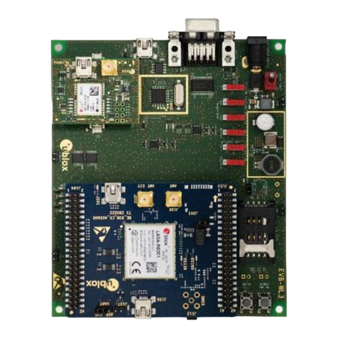
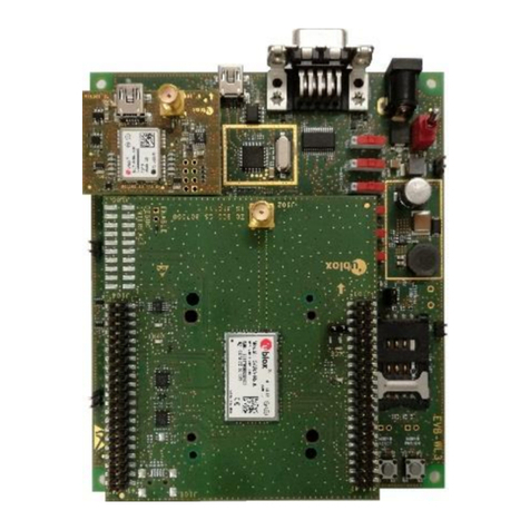
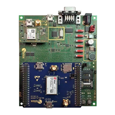
The EVK-N3 evaluation kit is formed by three boards:
•The lower one, called EVB-WL3, contains the power supply and other peripherals for the SARA-N3
series cellular module (such as SIM card holder, reset button and power-on button).
•The cellular adapter board, called ADP-N3, contains the SARA-N3 cellular module, the cellular
antenna connector, a 3-pin header with jumper for the digital I/O interfaces (GDI) voltage selection,
a 2-pin header with jumper for VCC and current consumption measurement, and the DIL
connectors (J101 and J102).
•The GNSS adapter board, called ADP-GNSS, contains the u-blox GNSS module, the GNSS antenna
connector and the USB connector for the GNSS module.
The boards are connected by means of male header board-to-board connectors provided on the
bottom of the adapter boards and their corresponding female connectors provided on top of the lower
board.
The SARA-N3 series pins are available on the dual in-line male board-to-board connectors provided on
the top layer of the cellular adapter board (J101 and J102), which are pin-to-pin compatible to the
connectors on the bottom layer of the adapter board EVB-WL3.
Communication with the SARA-N3 series cellular module is provided through the Cellular RS232 DB9
connector (J500) or the Cellular USB Mini-USB connector (J501), available on the EVB-WL3 board.
The UART interface of the SARA-N3 series cellular module is routed up to both the connectors - J500
and J501. The Mini-USB / DB9 slide switch (SW403) must be set according to the selected connector.
The Cellular USB Mini-USB connector (J501) provides also access to the additional UART interface
for firmware upgrade and tracing of the SARA-N3 series cellular module (see section 1.8).
The lower board (EVB-WL3) is designed also to be used with other u-blox cellular adapter boards. It
contains additional switches, jumpers, connectors, LEDs and parts that may be partially described in
Figure 1 or in this document, because they are intended for use only with other u-blox cellular modules.
It is recommended to leave any additional connector unconnected and any additional switch in its
default configuration.
