Uchida Yoko TAPIT-50W User manual

June 28,2006
OHKURA KOGYO CO.,LTD.
UCHIDA TAPIT-50W
SERVICE MANUAL
UCHIDA YOKO CO., LTD.

1
Safety Instructions
Definition of Symbols and Notes
In this manual following names and signs stand for possible dangers.
Danger
This Symbol stands for immediate danger threatening the life and health of
persons.
Disregarding these instructions may cause severe damage to health and even
serious injuries.
Caution
This symbol stands for an endangering situation that may occur.
Disregarding these instructions may lead to slight injuries or damage to property.
Note
This symbol stands for notes, operational hints and other useful information.
They are convenient for exploiting the machine’s functional abilities.
Caution
1. The internal temperature of the machine is very high during operation. Do not
touch the inside of the machine. Touching it may cause a burn.
2. When the power is turned on, do not put a hand inside the machine and in the
tape passage groove. There is a danger of an injury.
3. Do not spill any liquid such as water over the machine. Do not use any wet
article. Using such an article may cause an electric shock or failure.
4. When a failure occurs, lightning may occur or the machine is not used, pull out
the power plug from the plug socket. Keeping the machine in such a condition
without pulling out the power plug may cause a fire or electric shock.
5. Be sure to ground the machine. Operating the machine without grounding it
may cause an electric shock or fire.
6. Do not install the machine in an unstable place such a shaky base and an
inclined floor. Such installation may cause a fall or turnover, resulting an injury.

2
Contents
1. Brief Description of Each Section .........................................................................................3
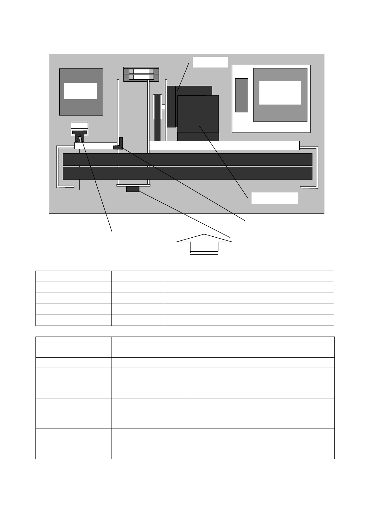
1. Reference assembly drawing of each section [Brief functional description of each section] 3
2. Function of each sensor or switch .......................................................................................... 4
3. Inching.................................................................................................................................... 5
2. Adjustment of Main Frame Section...................................................................................... 6
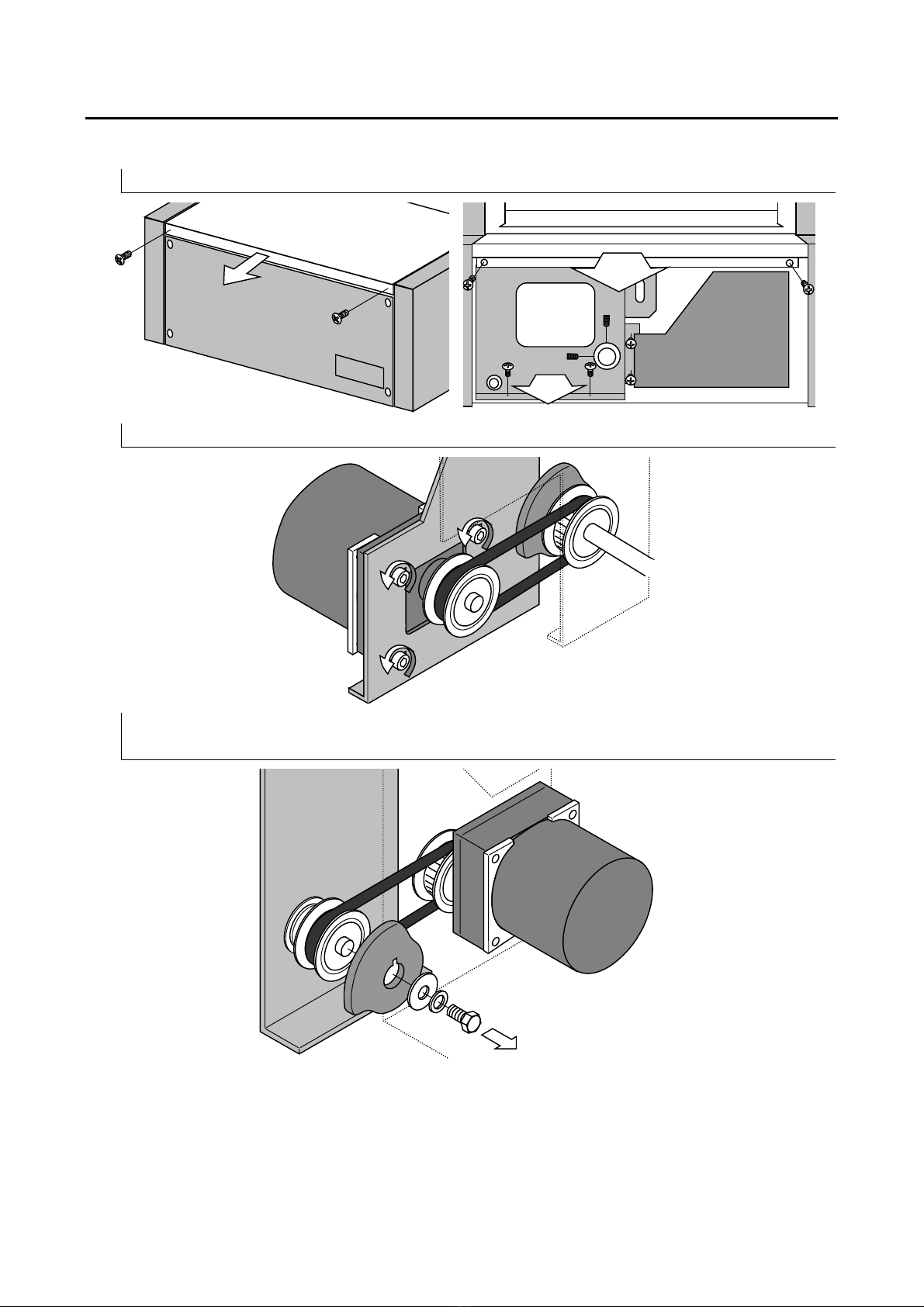
1. Replacement of spindle timing belt........................................................................................ 6
2. Adjustment of main spindle timing belt ................................................................................. 8
3. Adjustment of cutter section ...............................................................................................10
1. Replacement of cutter...........................................................................................................10
4. Adjustment of heater...........................................................................................................15
1. Replacement of heater.......................................................................................................... 15
5. Adjustment of hold plate section.........................................................................................18
1. Position check of sensor mounting plate.............................................................................. 18
2. Adjustment of sensor mounting plate................................................................................... 20
3. Adjustment of tape detecting plate....................................................................................... 23
6. Adjustment of tape reel section...........................................................................................25
1. Replacement of tape brake. .................................................................................................. 25
2. Adjustment of tape break........................................................................................................ 27
7. Adjustment of tape guide section........................................................................................28
1. Adjustment of wire............................................................................................................... 28
8. Adjustment...........................................................................................................................29
1. Installation of foot switch.....................................................................................................29
2. Starter Switch ....................................................................................................................... 29

3
1. Brief Description of Each Section
1. Reference assembly drawing of each section
[Brief functional description of each section]
1: Main frame section
[Internal side plate, main motor, main spindle]
2: Heater/cutter section
[Heater for deposition, tape press-down, tape cutting]
3: Hold plate section
[Tape deposition support plate, tape press-down support plate, tape detection]
4: Tape feed/tightening section
[Take lead-in, tightening]
5: Tape reel section
[Tape reel setting, tape braking]
6: Tape guide section
[Fed-out tape guide, tape holding]
7: Main unit section
[Outside covers, switches]

4
2. Function of each sensor or switch
Near side
Item sensor
Taper sensor
Main spindle sensor A/B
Main motor
Tape feed motor
PCB
OUK-071D
Heater
transformer
Sensor name Model No. Function
Main spindle sensor A EE-SX670 Detects the main spindle position.
Main spindle sensor B EE-SX670 Detects the main spindle position.
Tape sensor EE-SX671 Detects whether a tape is at the bundle enable position or not.
Item sensor KR895 Detects whether an item is on the table or not.
Switch name Model No. Function
POWER switch JW-M21RKK Turns on and off the main power supply.
Temperature control knob RV24YN20SB1kΩControls the heater temperature
START switch KSW-R00 (switch)
KTA-0227
(STRAT key top)
Starts bundling
Returns the main spindle to the initial position.
Selects between enable/disable for the item sensor.
AUTO switch KSW-R00 (switch)
KTA-0117
(AUTO key top)
Sets the AUTO start function.
TAPE FEED switch KSW-R00 (switch)
KTA-0117
(TAPE FEED key top)
Feeds the tape.

5
3. Inching
Inching is performed by a switch provided on the PCB. While the INCHING switch is pressed,
the main motor is operated.
After pressing the INCHING switch, press the START switch to return the main spindle to the
initial position. The main motor will be operated and the main spindle will be returned to the
initial position. If the main spindle is at the initial position even after the INCHING switch is
pressed, the main motor is not started.
OUK-071D
INCHING Switch
CPU
In addition, inching can be performed according to the condition of the switches when the
power switch is turned on. If the power switch is turned on while the AUTO switch and TAPE
FEED switch are pressed, the INCHING mode can be set. Under the INCHING mode, if the
TAPE FEED switch is pressed while the AUTO switch is pressed, inching will be performed.
To release the INCHING mode, turn off the power.

6
2. Adjustment of Main Frame Section
1. Replacement of spindle timing belt
1. Remove the rear table, rear cover, front table and switch panel.
M4 x 8
set screw
x 2
2. Loosen the main motor mounting screw.
3. After removing the mounting screw fixing the roller pressure cam, remove the roller pressure
cam.

7
4. Remove the old timing belt and replace it with a new timing belt.
5. Mount the roller pressure cam.
6. Make adjustment according to “2. Adjustment of spindle timing belt.”

8
2. Adjustment of main spindle timing belt
After the main motor or the gear head is replaced, the main spindle timing belt (Hereinafter
referred to as the belt) must be adjusted.
1. Tentatively fit the main motor and the gear head loosely using mounting screws and fix the
motor side pulley on the gear head spindle.
Clearance between the metal
plate and the pulley: 9mm
2. Put the belt on the motor side pulley and main side pulley.

9
3. Pull the main motor backward to uniform the belt tension between on the upper side and on the
lower side, and tighten the mounting screws to an extent that the main motor may not be moved
easily.
4. Push the middle of the belt lightly on the upper side and lower side with fingers and fix the main
motor at the position where the middle of the belt is flexed about 1 to 2 mm.
The belt should flex 1 to 2mm
when lightly pushed down with your fingers.
* The belt will be considerably tightly stretched.

10
3. Adjustment of cutter section
1. Replacement of cutter
When the tape is hard to cut, the cutter must be replaced. When replacing the cutter, replace
both upper blade and lower blade as a set if possible.
1. Remove the rear table, front table, and switch panel.
M4x8
Set screw
x2
2. Remove the hold plate.
3. Remove the connection line fixed at the heater connecting terminal. (On both sides)

11
4. Remove the tension coil springs (2 locations) provided around the heater
Remove these
two springs.
5. Press the INCHING switch to rotate the main spindle to cause the heater to go to the top dead
point.
Tape guide Tape guide
6. Turn off the power switch.
7. While opening the tape guide by hand, take out the heater section.

12
8. While opening the tape guide by hand, take out the tape press-down section
9. Remove the tape cutter while taking care not to cause the springs to jump out, and then install a
new tape cutter.
2. Remove the cutter while holding these springs
b
y hand so as not to cause them to jump out and
be lost.
1. Remove one of the bosses.
Thrust Washer

13
10. Remove the tension coil spring of the tape press-down section, remove the cap bolts provided
on the tape holder (1), and install a new tape holder (1)
Cap bolt M4 x 8
Spring washer 4
Stainless spacer CU-406
Pan-head screw
M4x16 Nut M4
11. While opening the tape guide by hand, install the tape press-down section.
12. While opening the tape guide by hand, install the heater section
13. Turn the power switch on and set the main spindle to the initial position.

14
14. Remove the tension coil spring removed in step 4.
Wire diameter: 1.2mm
Spring diameter: 11.2mm
Wire diameter: 1.2mm
Spring diameter: 9.2mm
15. Install the connection line at the heater connecting terminal.
M4 x 8 cap bolt (Sems)
Flat washer φ4 (small round)
Tighten it firmly
to prevent a connection fault
16. Install the holder plate.
Insert the slide fixture into
the push nut of the spring pin.
Slide fixture
Link ar
m
Slide plate
Hold plate
View from
the near side
17. Install the switch panel, front table, and rear table.
M4 x 6
truss machine screw
M4 x 8
set screw
x 2
M4 x 6
truss machine screw
x 4
M4 x 6 pan-head
screw(W sems)
x 2

15
4. Adjustment of heater
1. Replacement of heater
When the tape is hard to deposit, the heater must be replaced.
1. Remove the rear table and front table.
2. Remove the hold plate.
3. Remove the tension coil spring provided around the heater.
Remove this spring.

16
4. Press the INCHING switch to rotate the main spindle to cause the heater to go to the top dead
point.
Tape guide Tape guide
5. Turn the power switch off.
6. Hoist the heater section to the position where the heat fitting screws can be loosened.
7. Remove the old heater. If crack or void is caused in the heat insulating material, it is necessary
to replace it.
8. Install a new heater.
Install the insulating material in curved form as shown
in the figure so that the insulating material may be
brought into close contact with the heater. If they are
not in close contact, this will cause lack of thermal
uniformity.
Tighten these screws securely to
prevent a contact fault.
M3 x 4 pan-head machine screw
Flat washer φ3 (small round)

17
9. Push in the heater section.
10. Install the tension coil spring removed in step 3.
Wire diameter: 1.2mm
Spring diameter: 11.2mm
11. Turn the power switch on and set the main spindle to the initial position.
12. Install the hold plate.
Insert the slide fixture into
the push nut of the spring
p
in.
Slide Fixture
Link arm
Slide plate
Hold plate
View fro
m
the near side
13. Install the rear table and front table.
M4 x 6
Truss machine screw
M4 x 8
Set screw
X 2
M4 x 6
Truss machine screw
X 4
M4 x 6 pan head
(W sems)
X 2

18
5. Adjustment of hold plate section
1. Position check of sensor mounting plate
If the hold plate section (1) and the press-down plate (2) are not properly positioned, the tape
will not be held firmly, and, the deposition section will deviate or the tape will get out of place
when tightening it.
1. Remove the rear table.
2. Cut the film tape about 10 to 20 cm and insert it between the tape press-down plate (1) and the
hold plate.
10 – 20cm
Tape
3. Press the INCHING switch to move the main spindle to the position where the tape press-down
plate (1) touches the hold plate and the guide is fully opened. (Position where the heater is not
raised.) The tape is interposed between the hold plate and the tape press-down plate (1).

19
4. Stretch the tape and check that there is no difference in nipping force between the near side and
the far side.
○
×
×
If the tape can be stretched straight, it is OK.
If the tape is curved, it must be adjusted.
Table
Hold plate
]
5. Press the START switch to cause the main spindle to go to the initial position.
6. In the same way as above, cut the film tape about 10 to 20 cm and insert it between the tape
press-down plate (2) and the hold plate.
10 – 20 cm
Tape
7. Press the INCHING switch to move the main spindle to the position where the heater touches
the hold plate and spindle is placed one level lower from it. (Position where the heater is
lowered and the rape us held only by the tape press-down plate (2). ).
Tape
Position where the main spindle is stopped.
Table of contents
Popular Packaging Equipment manuals by other brands

HAITEC
HAITEC HT-KJ20 Series Quick start manual

Smipack
Smipack FP560 Use and maintenance manual

Z.R. Tools
Z.R. Tools MS25-1 Operation manual

AETNAGROUP
AETNAGROUP ROBOPAC ROTOPLAT Use and maintenance manual

Signode
Signode BXT 10 Operation, parts and safety manual

Transpak
Transpak TP-201 Operation manual & spare parts list

Francotyp-Postalia
Francotyp-Postalia FPi 5020 Operator's manual

U-Line
U-Line H-1459 manual

AirBo
AirBo AED1223 manual

Fromm
Fromm P326 Operation manual & spare parts list

MSW Motor Technics
MSW Motor Technics MSW-MST25 user manual

M.J. MALLIS GROUP
M.J. MALLIS GROUP SIAT SM26-P Instruction manual and spare parts list