uhlmann & zacher CX2172 Product guide

CX2172/4
Clex private
Electronic door handle
Operating and
assembly manual

CX2172/4 TABLE OF CONTENTS
2
Imprint
Operating and assembly manual
Electronic door handle CX2172/4
Document number: 0704
Version: 1.41
Status: 09.07.2018
Manufacturer
Uhlmann & Zacher GmbH
Gutenbergstr. 2–4
97297 Waldbuettelbrunn
Germany
Tel.: +49 931 40672-0
E-Mail: contact@UundZ.de
http://www.UundZ.com
This operating and assembly manual is copyright protected. The information
contained this manual should not be reproduced, distributed or used for
competitive purposes or shared with third parties. It is likewise forbidden to
manufacture any component using this manual without prior written consent.

CX2172/4 TABLE OF CONTENTS
3
Table of contents
1About this document ........................................................................ 5
1.1 Warnings ............................................................................................5
1.2 Symbols..............................................................................................5
2Security .......................................................................................... 6
2.1 Proper use ..........................................................................................6
2.2 Improper use.......................................................................................6
2.3 General safety instructions....................................................................6
3Product description .......................................................................... 7
3.1 Functional description ..........................................................................7
3.2 Design................................................................................................9
3.3 Versions............................................................................................12
3.4 Technical data ..................................................................................13
3.5 Standards .........................................................................................17
3.6 Management accessories ...................................................................18
4Assembly .......................................................................................19
4.1 Assembly instructions .........................................................................19
4.2 Assembly ..........................................................................................20
5Commissioning ..............................................................................32
5.1 Programming the service key ..............................................................32
5.2 Management as programming / clearing system ..................................32
5.3 Management with Keyng CX2530.......................................................33
5.4 Changing the settings ........................................................................33
6Operation .....................................................................................34
6.1 Automatic wake up ............................................................................34
6.2 Opening the door..............................................................................34
6.3 Toggling the door handle...................................................................35
6.4 Signals .............................................................................................36
7Cleaning and maintenance..............................................................37
7.1 Cleaning...........................................................................................37
7.2 Maintenance .....................................................................................37
8Faults during operation ...................................................................40
8.1 Fault indications ................................................................................40
9Disassembly and Disposal................................................................41
9.1 Disassembly ......................................................................................41
9.2 Disposal ...........................................................................................43
10 FAQ .............................................................................................44
10.1 Door handle does not come to rest position.........................................44

CX2172/4 TABLE OF CONTENTS
5
1About this document
This operating and assembly manual describes the Clex private electronic door
handle in rosette fitting (in short: CX6172) and the electronic door fitting (in short:
CX2174). It is part of the product and contains important information that is
necessary for proper operation and maintenance.
This operating and assembly manual is valid for all versions of CX2172 and
CX2174 and is intended for technicians, who are responsible for assembling and
disassembling, as well as for end customers.
Read this operating and assembly manual carefully for smooth and safe
operation and follow the instructions given in it before operating the door
handle.
Keep the operating and assembly manual in a safe place.
After the installation, hand over the manual to the end customer and make
sure that the customer familiar with its use.
Uhlmann & Zacher GmbH does not assume any responsibility for disruptions or
hazards such as as non-access to injured personnel, malfunctions, property
damage or other damages resulting from non-compliance with this operating and
assembly manual or incorrectly configured door handles.
If there are still any doubts after reading this operating and assembly manual,
please contact your respective dealer or Uhlmann & Zacher GmbH directly.
1.1 Warnings
Warnings warn against hazards which may arise when using the door handle.
There are two levels of warnings that can be identified based on the signal word:
Signal word
Meaning
CAUTION
Indicates a hazard with a low risk that can lead to mild or
moderate injury if not avoided.
ATTENTION
Indicates a hazard that results in property damage.
1.2 Symbols
The following symbols may be used in this manual:
This symbols indicates a usage instruction that must be followed by the user.
This symbol indicates an entry in a list.
This symbol indicates useful and important information.

CX2172/4 TABLE OF CONTENTS
6
2Security
2.1 Proper use
The electronic door handle CX2172/4 is intended to be installed in building
doors and for opening the doors. It is compatible with the commonly used
European standards for locking systems.
The different versions allow it to be used in all the common doors such as wood,
steel and aluminum doors as well as doors with narrow frames having a backset
of more than 18 mm (depending on the product version).
The CX2172/4 can be used indoors as well as outdoors (depending on the
product version).
The version for fire and smoke-resistant doors, emergency exit locks can be used
on the corresponding doors. The applicable regulations should be followed.
2.2 Improper use
The CX2172/4 should not be used for locking up supplies required in case of
emergencies (for example defibrillator, emergency medication, fire extinguishers,
etc.).
The CX2172/4 should not be used in potentially explosive surroundings.
Specially approved versions that are intended for the purpose should be installed
and used in fire, smoke resistant doors and emergency exit locks. The applicable
regulations should be followed.
The CX2172/4 should not be used if the housing or the electronics is damaged.
Changes or retrofits to the product are not allowed. The knob module should not
be used outside the given specifications.
The CX2172/4 should not be used in doors that do not open freely or in doors or
lock cases that are damaged. The product should not be used as a stopper
against obstacles.
2.3 General safety instructions
Follow these basic safety instructions when using the door handle:
Installation and battery replacement should only be done by qualified
technicians according to the instructions in this operating and assembly
manual.
Do not use the door handles in potentially explosive areas.
Do not make any kind of modifications to the door handles, with the
exception of those described in this operating and assembly manual.
Do not apply paints or acids to the door handles.
Do not heat the door handle and battery beyond the specified storage
temperature.
Use only original spare parts and accessories from Uhlmann & Zacher to
prevent malfunctions and damages.
Only use batteries procured from Uhlmann & Zacher.

CX2172/4 TABLE OF CONTENTS
7
3Product description
3.1 Functional description
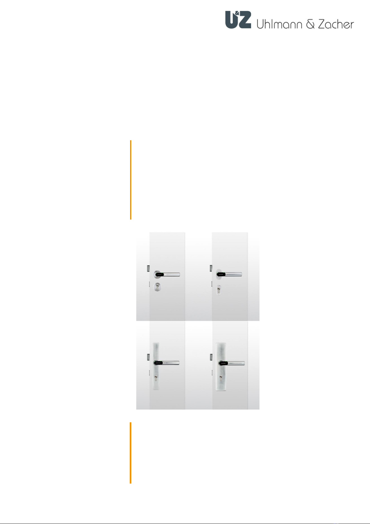
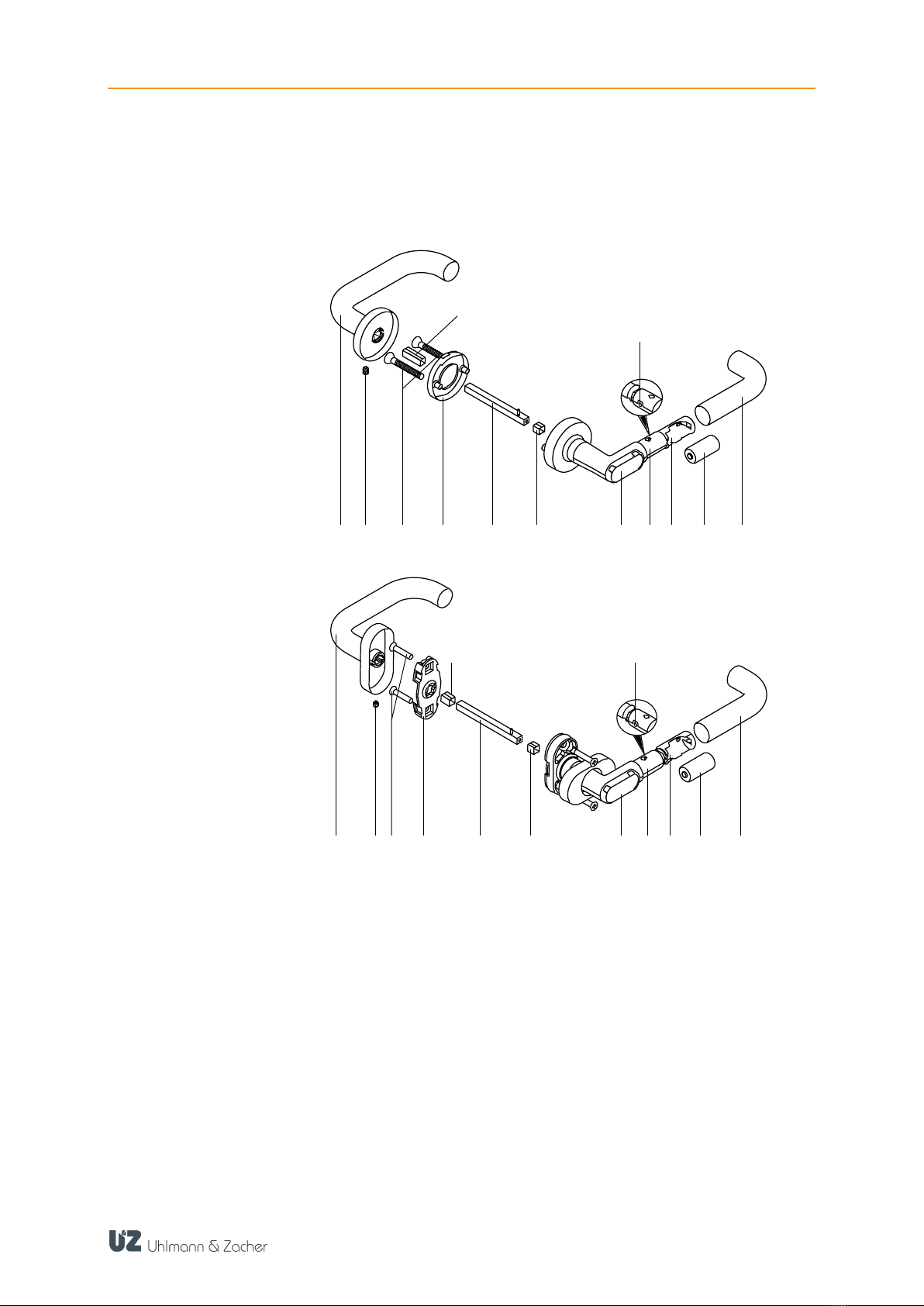
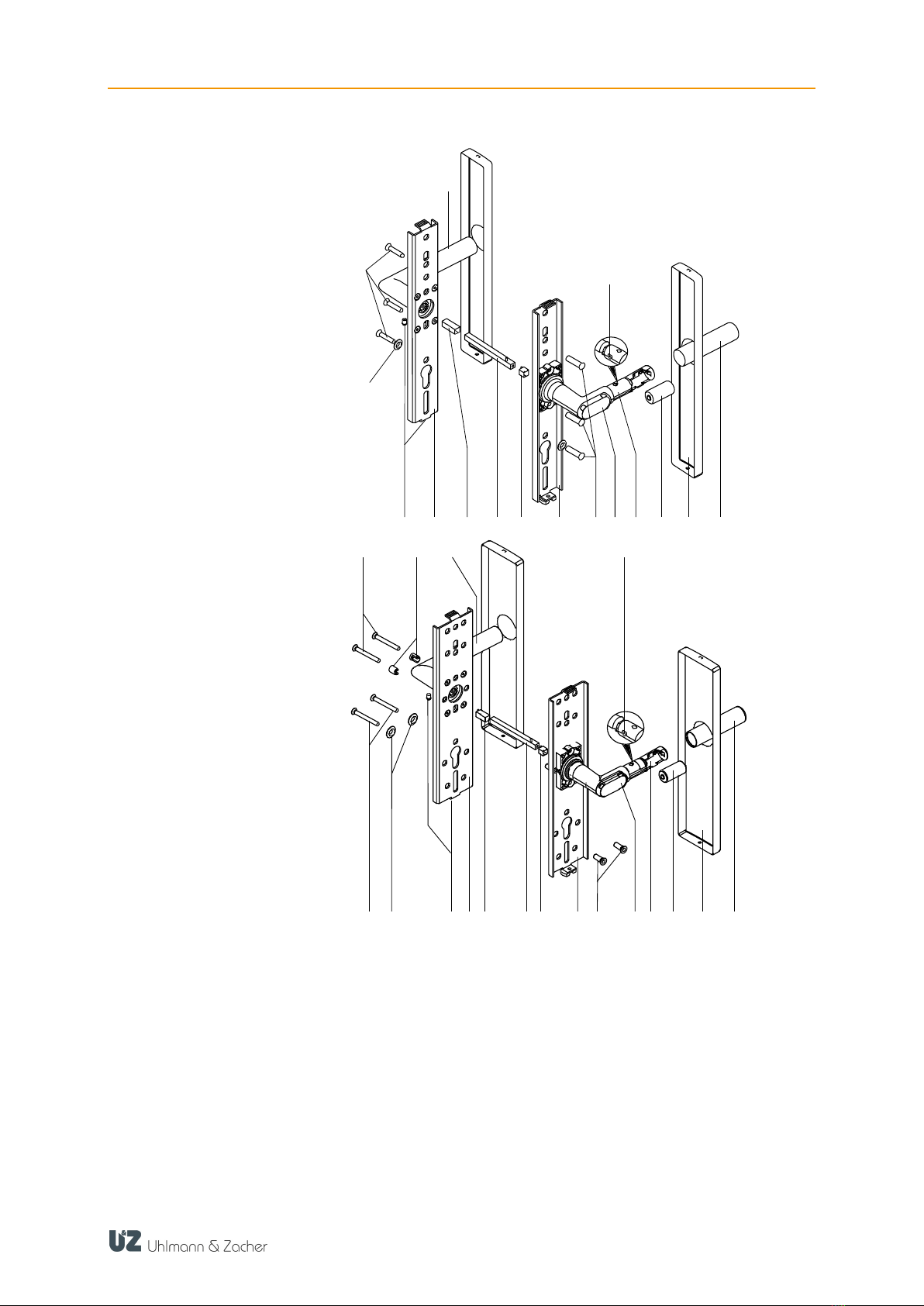
The electronic door handle CX2172/4 is a product in the Clex private system.
The reading unit, the communication electronics, the mechanical system and
power supply, are integrated within the door handle.
Different transponder carriers can be used as key in the CX2172/4, for example,
ISO card or key fob.
CX2172/4 has the following system properties:
Up to 1,000 key/locking authorizations can be stored
Up to 128 events can be recorded in the fitting*
Up to 32 holidays can be configured*
Automatic summer and winter time changeover*
15 weekly schedules can be programmed*
Permanent engagement possible without additional power consumption
Engagement time can be programmed from 1 to 15 seconds
Can be connected to the IDS module CX6934
Pre-configured by default for 868 MHz wireless networking
Inner fitting fixed mechanically (only for one-sided electronic authorization)
Different handle shapes available
Suitable for all doors having a thickness of 30 mm to 110 mm
Square thickness of 7 mm, 8 mm, 8.5 mm, 9 mm and 10 mm are available
No cabling required
Can be combined with other systems (for example Clex prime)
Version for MIFARE®transponder available
Optional management via the CX2530 Keyng software
3.1.1 Battery management
The electronic door handle CX2172/4 comes with a battery management system,
which indicates the need for battery replacement by means of a visible and audio
signal, when the battery power reduces (capacity loss) during the final 1,000
operations of the battery (see chapter 7.2.1 Battery Replacement).
The signal is given out in two phases:
The battery needs to be changed soon.
If an authorized key is held in front of the reading unit, then the engaging of the
door handle is accompanied with flashing of red light (5 times) and 5 short
audible signals.
The battery needs to be changed immediately.
If an authorized key is held in front of the reading unit, then the red LEDs flash (5
times) accompanied by 5 short audible signals. The engaging of the door handle
is delayed by 5 seconds, during which time the green LEDs flash.
The access data, the events log, the settings of the cabinet lock and the time are
stored on non-volatile memory and thus retained even when there is no power
supply, for example, when changing the battery or if the battery discharges
completely. The time is written to the non-volatile memory once every 30 minutes.
If the power supply remains off, then the clock comes to a standstill after a few
seconds and starts running from the last stored value onwards after the power
supply is restored.
*When using CX2530 Keyng
Phase 1
Phase 2

CX2172/4 TABLE OF CONTENTS
8
3.1.2 Event log
The last 128 events of the door handle are stored in the event log.
Event logging can be enabled or disabled for each door handle individually, to
comply with specific data privacy guidelines.
The event log can be read via the CX2530 Keyng.

CX2172/4 TABLE OF CONTENTS
9
3.2 Design
3.2.1 One-sided electronic authorization
12
1 2 3465 78910 11
6
1 2 345 6 78910 11
126
1
Mechanical door handle
7
Reading unit
2
Locking screw
8
Electronic door handle
3
Mounting screw
9
Battery compartment
4
Opener holder (with bayonet
lock)
10
Battery
5
Square pin with spiral
clamping
11
Gripping sleeve
6
Adapter sleeve (only for 7 mm
square pin)
12
Grub screw for gripping sleeve
Circular rosette
Oval rosette

CX2172/4 TABLE OF CONTENTS
10
1
345 6 5 4 7 8910 11 12
13
14
2
1 2
1
345 6 5 78910 11 12
13
14
15
4
1
Mounting screws
9
Electronic door handle
2
Washers
10
Battery
3
Locking screws
11
Plate cover
4
Base plate
12
Gripping sleeve
5
Adapter sleeve (only for 7 mm
square pin)
13
Grub screw for gripping sleeve
6
Square pin with spiral
clamping
14
Mechanical door handle
7
Threaded sleeves
15
Screw-type sleeve
8
Reading unit
Long narrow plate
Long wide plate

CX2172/4 TABLE OF CONTENTS
11
1
Mounting screws
7
Locking screw
2
Mechanical door handle
8
Threaded sleeve
3
Grub screw for gripping sleeve
9
Electronic door handle
4
Locking screw
10
Battery
5
Square pin with spiral
clamping
11
Plate cover
6
Adapter sleeve (only for 7 mm
square pin)
12
Gripping sleeve
Short plate

CX2172/4 TABLE OF CONTENTS
12
3.2.2 Two-sided electronic authorization
Two-sided electronic authorization is possible only in certain combinations of the
variants circular rosette, oval rosette, long narrow plate and long wide plate.
1
Reading unit
6
Rosette cover
2
Electronic door handle
(outside)
7
Electronic door handle (inside)
3
Square pin
8
Battery
4
Adapter sleeve (only for 7 mm
square pin)
9
Gripping sleeve
5
Mounting screw
10
Grub screw for gripping sleeve
3.3 Versions
Different opener shapes and versions are available:
Door openers in L-shape or U-shape
One or two-sided electronic authorization
Circular rosette, oval rosette, long narrow plate and long wide plate
For emergency exit locks, fire and smoke resistant doors
For door hinged on the right or left
For indoor or outdoor use
Various square sizes (7 mm, 8 mm, 8,5 mm, 9 mm, 10 mm)

CX2172/4 TABLE OF CONTENTS
13
3.4 Technical data
3.4.1 General technical data
Name
Value
Minimum backset
Circular rosette: 28 mm
Oval rosette: 18 mm
Long narrow plate: 22 mm
Long wide plate: 33 mm
Door thickness
30 mm to 110 mm
Maximum door weight
300 kg
Swivel angle
45°
Transponder
MIFARE®Classic (868 MHz)
MIFARE®DESFire® (868 MHz)
Active transponder (868 MHz)
Radio
Frequency: 868.3 MHz
Maximum transmission power: 1 mW
Power supply,
Rated voltage
CR123A 3V battery (1 piece),
3 volts
Battery life
up to 170,000 operations or 9.8 years
Power consumption in
sleep mode
0.06 mW
3.4.2 Ambient conditions
Name
Value
Operating
temperature
+5°C to +55°C (indoor version)
-25°C to +65°C (outdoor version)
Storage
temperature
-40°C to +65°C
Maximum relative
humidity (door
handle)
Up to 95% non-condensing
Installation location
Indoor or outdoor (depending on the product model)
Protection class
Indoor version: IP40
Outdoor version: IP66

CX2172/4 TABLE OF CONTENTS
14
3.4.3 Dimensions
Circular rosette
electronics side and
handle versions
Circular rosette
mechanical side and
handle versions
Oval rosette
electronics side
Oval rosette
mechanical side

CX2172/4 TABLE OF CONTENTS
15
14,7
79,0
14,7
75,5
Long narrow plate
electronics side
Long narrow plate
mechanical side

CX2172/4 TABLE OF CONTENTS
16
14,7
79,0
75,5
14,7
Long wide plate
electronics side
Long wide plate
mechanical side

CX2172/4 TABLE OF CONTENTS
17
75,5
14,7
3.5 Standards
The electronic door handle CX2172/4 meets the following standards:
prEN 16867:2015
EN 1906:2012
Short plate electronics
side
Short plate mechanical
side
14,7
79,0

CX2172/4 TABLE OF CONTENTS
18
3.6 Management accessories
3.6.1 CX2530 Keyng
The CX2530 Keyng management software helps easy management of the
electronic locking system Clex private via the PC. The software, in comparison to
the learning / clearing system, offers an extended function range.
The communication between the locking units and the management software
takes place via a USB wireless stick.
3.6.2 Service key
Using the service key, a user identifies himself as an administrator of the locking
system. If the service key is held in front of a component of the locking system,
then the respective component goes into programming mode. It is then possible,
for example, to authorize keys, adjust settings or read the event log.

CX2172/4 TABLE OF CONTENTS
19
4Assembly
4.1 Assembly instructions
CAUTION
Damage to the door handle by mounting screws that are too
long
The cover of the electronic door handle can be damaged if
the mounting screws are too long!
4.1.1 General assembly instructions
Check the approval when installing the CX2172/4 door handle in a fire /
smoke resistant door or in an escape door.
If a cylinder holder is present in the door, then it should be sealed properly,
for e.g. using a dummy cylinder.
Carry out the assembly with the door open.
Ensure that the latches or seals fitted to the door do not hinder the proper
operation of the CX2172/4.
Ensure that the door handle does not protrude and prevent the door from
swinging freely.
When installing the CX2172 door handle in the circular and oval rosettes
version, the hole in the door for inserting the handle pin should have a
diameter of at least 25 mm.
When installing the CX2174 door handle in the long plate version, the plate
has to be fixed at least at four points distributed as evenly as possible over the
length, such that the corresponding force can be applied on the plate.
Before assembling the door handle, always check whether all the components
can move freely.
After assembly, check the function with the door open.
4.1.2 Drilling template
The drilling template supplied is used to mark the drilling holes.
There should be a distance of at least 38 mm between the two drilling holes for
the handle rosette and that for the key rosette.
There should be a distance of at least 50 mm between the two drilling holes for
the handle rosette and that for the key rosette.
The base plates of the two long plate versions are provided with holes for
different doors. Usually the same holes are used for the long narrow plate version
as for the oval rosettes versions, for the wide version that of the circular rosette
version.
The base plate of the short plate is provided with holes for mounting a short
plate. Usually the upper short plate hole and a hole below the locking cylinder
are used for fixing.
Circular rosette
Oval rosette
Long plate
Short plate

CX2172/4 TABLE OF CONTENTS
20
4.2 Assembly
4.2.1 Assembling the square pin
The square pin has to be assembled before installation on the electronic
door handle (outside). This applies to all the versions and is shown here
using an example of the circular rosette version.
1
Electronic door handle
2
Spiral clamping pin
3
Square
4
Adapter sleeve for square (only for 7 mm square)
Insert the adapter sleeve into the square holder (if required)
Insert the square onto the retaining pin and into the square holder
Insert the spiral clamping pin into the square
1
3
2
4
Other manuals for CX2172
1
This manual suits for next models
1
Table of contents
Other uhlmann & zacher Door Lock manuals