Ultralife CH0004 User manual

CH0004 Operation Manual
Newark, New York |315-332-7100 |Fax: 315-331-7800
©2010 Ultralife Corporation • www.ultralifecorp.com • All specific subject to change without notice
The information contained herein is for reference onl
y
and does not constitute a warrant of
p
erformance • 30 SEP 10 UBI-5157 Rev: E
CH0004 Battery Charger/Conditioner
Operation Manual
Ultralife Corporation
2000 Technology Parkway, Newark, NY 14513 USA
Telephone (315) 332-7100 FAX (315) 331-7800
E-MAIL: [email protected]
www.ultralifecorporation.com

Copyright
Copyright © 2010, Ultralife Corporation. All Rights Reserved.
Disclaimer of Liability
Information and descriptions contained in this manual are the property of Ultralife Corporation.
Distribution and/or reproduction in part or in whole are expressly forbidden without written consent.
Ultralife Corp believes that information in this publication is accurate as of its publication date.
Ultralife Corp reserves the right to change the contents without prior notice and is not responsible for
any inadvertent errors.
Ultralife Corporation
2000 Technology Parkway
Newark, New York 14513
Phone: (315) 332-7100
Fax: (315) 331-7800
Email: [email protected]
http://www.ultralifecorporation.com
CH0004 Operation Manual
Newark, New York |315-332-7100 |Fax: 315-331-7800
©2010 Ultralife Corporation • www.ultralifecorp.com • All specific subject to change without notice
The information contained herein is for reference only and does not constitute a warrant of performance • 30 SEP 10 UBI-5157 Rev: E
Page 2 of 15

CH0004 Operation Manual
Newark, New York |315-332-7100 |Fax: 315-331-7800
©2010 Ultralife Corporation • www.ultralifecorp.com • All specific subject to change without notice
The information contained herein is for reference only and does not constitute a warrant of performance • 30 SEP 10 UBI-5157 Rev: E
Page 3 of 15
CONTENTS
CONTENTS ...............................................................................................................................3
1ABOUT THIS MANUAL................................................................................................4
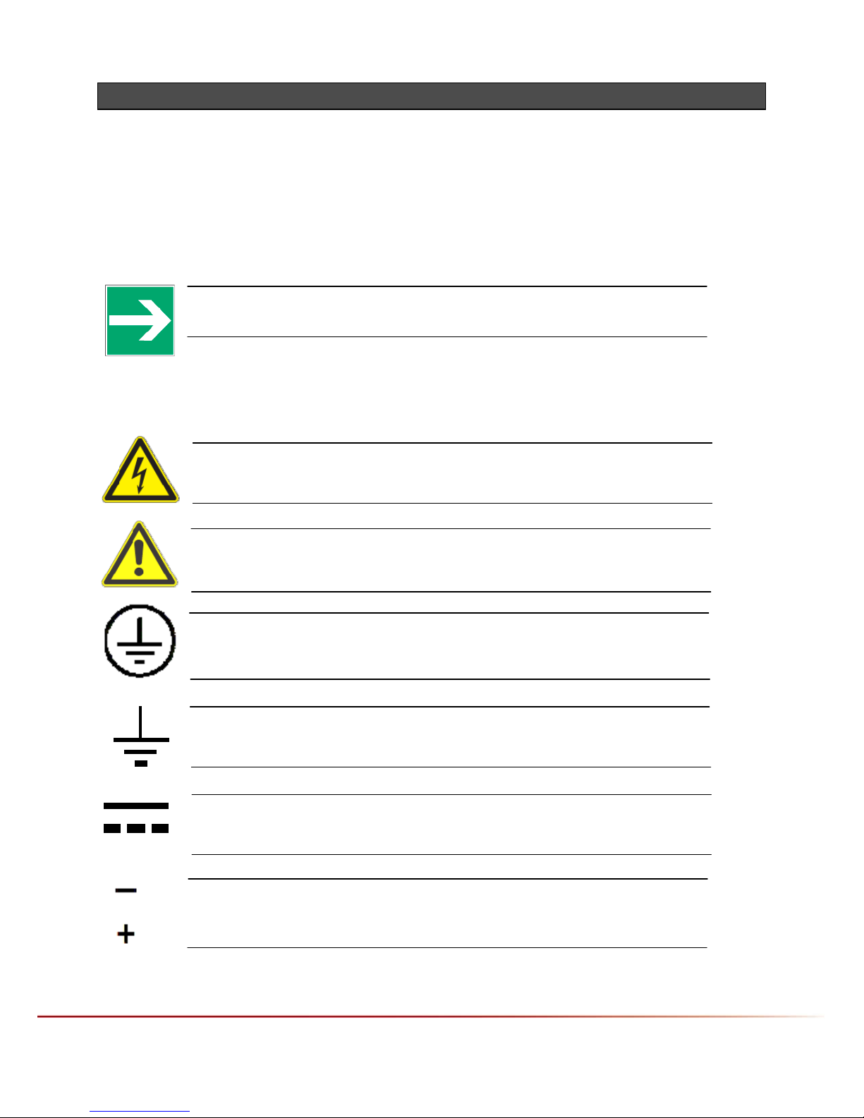
1.1 SYMBOLS USED.................................................................................................................4
1.2 GENERAL SAFETY INSTRUCTIONS.......................................................................................5
2PRODUCT DESCRIPTION...........................................................................................6
2.1 FEATURES.........................................................................................................................6
2.1.1 Charge Detection .................................................................................................6
2.1.2 Lithium Ion Battery Detection...............................................................................6
2.1.3 NiCad OR NiMH Battery Detection ......................................................................6
2.1.4 Temperature Detection.........................................................................................7
2.1.5 Unattended Charging...........................................................................................7
2.1.6 Wide Range Input Voltage ...................................................................................7
2.1.7 Conditioning Cycle ...............................................................................................7
2.1.8 Equipment Provided.............................................................................................7
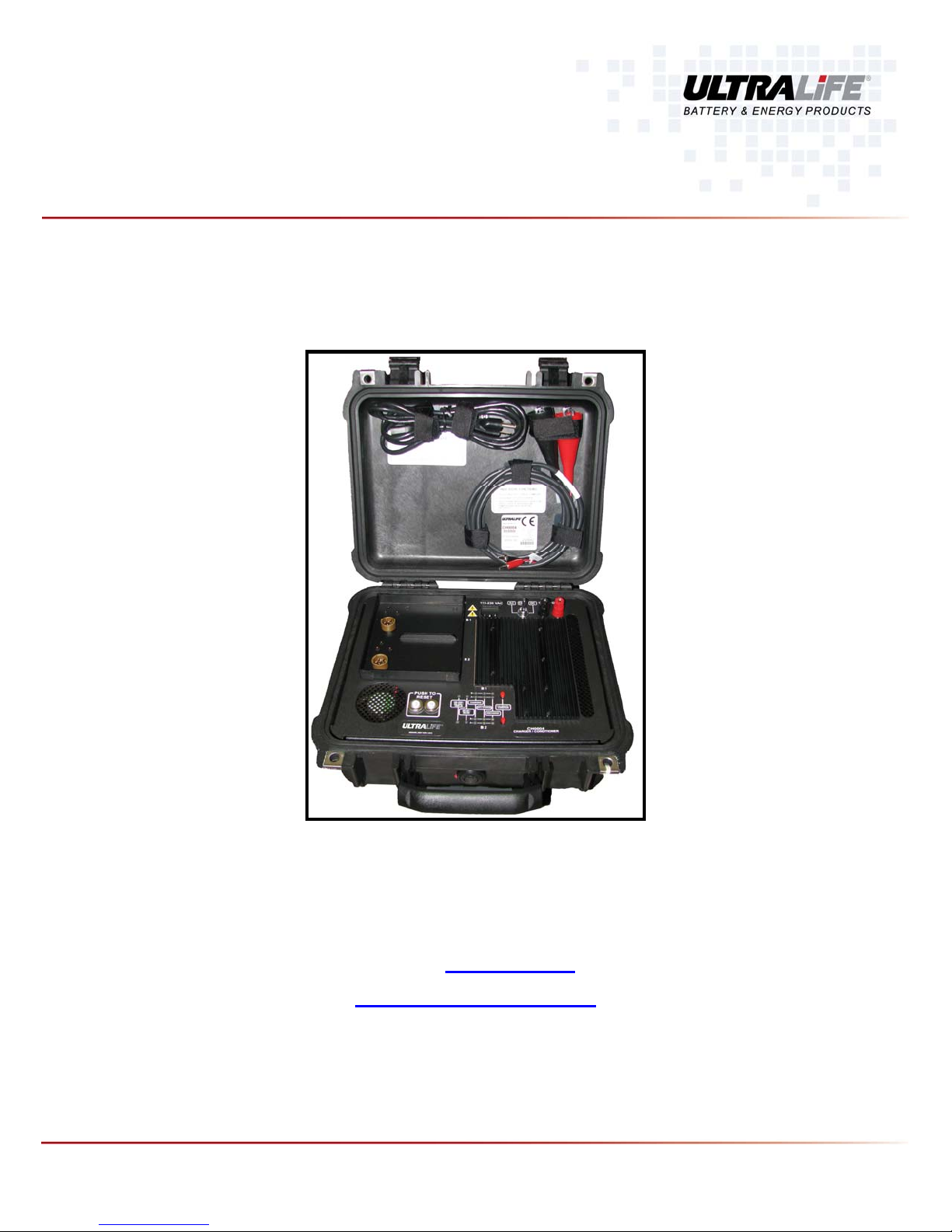
2.2 PHYSICAL DESCRIPTION.....................................................................................................8
2.3 FUNCTIONAL DESCRIPTION ................................................................................................8
2.3.1 Charge Supply......................................................................................................8
2.3.2 Control/Filter Board..............................................................................................8
2.3.3 AC to DC Power Supply.......................................................................................8
3OPERATION.................................................................................................................9
3.1 GROUNDING CONNECTIONS ...............................................................................................9
3.2 AC POWER CORD CONNECTIONS.......................................................................................9
3.3 BATTERY SELECTION,CHARGING AND CHARGE CYCLE .......................................................9
3.4 BATTERY DISCHARGE ......................................................................................................10
3.5 START-UP .......................................................................................................................10
3.6 LED INDICATORS.............................................................................................................11
3.6.1 Battery Type” Indicator LEDs.............................................................................12
3.6.2 “Charging” Indicator LEDs..................................................................................12
3.6.3 “90% Charge” Indicator LEDs ............................................................................12
3.6.4 “Discharge” Indicator LEDs................................................................................12
4MAINTENANCE..........................................................................................................13
4.1 CLEANING .......................................................................................................................13
4.1.1 Dirt and Dust.......................................................................................................13
4.1.2 Oils and Grease .................................................................................................13
4.2 CORRECTIVE MAINTENANCE.............................................................................................13
5CUSTOMER ASSISTANCE .......................................................................................14
5.1 WARRANTY INFORMATION................................................................................................14
5.2 CONTACT/RETURN INFORMATION .....................................................................................14
6SPECIFICATIONS......................................................................................................15

1 ABOUT THIS MANUAL
This manual has been prepared by Ultralife Corp for the purpose of providing a maintenance
technician the information necessary to understand and to maintain the CH0004 Battery
Charger/Conditioner.
1.1 Symbols Used
The symbols shown in this section appear throughout this manual, the first one shown being the
NOTE symbol, below, which is self-explanatory.
NOTE: Note statements contain important information that may affect
how you use this product.
The other symbols represent important safety advice, and they appear throughout this manual and
on the CH0004 in the form of WARNINGS and CAUTIONS against possible hazards to people or
equipment, respectively. These safety WARNINGS and CAUTIONS must be followed at all times.
WARNING: Warning statements mean danger. They identify practices, procedures
or conditions such as high voltage that could result in injury or loss of life and
which, therefore, require extreme care before proceeding.
CAUTION: Caution statements denote a hazard. They identify practices,
procedures or conditions that could result in damage to or destruction of this
product or other equipment or property.
Ground: This symbol is placed adjacent to grounding locations on the unit. These
areas are designed to be connected to an earth ground either through a power
cable or grounding cable to prevent injury to the user.
Ground: This symbol is placed adjacent to grounding locations on the unit. These
areas are designed to be connected to an earth ground either through a power
cable or grounding cable to prevent injury to the user.
Direct Current: This symbol is placed adjacent to the Direct Current (DC) input
location on the unit. This connector is designed to be connected to only a DC
source.
DC Polarity: These two symbols are placed next to their corresponding DC input
connectors to identify positive and negative to the user. The “+” symbol indicates
the red positive terminal, and the “-“symbol indicates the black negative terminal.
Ultralife Corp assumes no liability for the customer’s failure to comply with these
WARNINGS and CAUTIONS.
CH0004 Operation Manual
Newark, New York |315-332-7100 |Fax: 315-331-7800
©2010 Ultralife Corporation • www.ultralifecorp.com • All specific subject to change without notice
The information contained herein is for reference only and does not constitute a warrant of performance • 30 SEP 10 UBI-5157 Rev: E
Page 4 of 15

1.2 General Safety Instructions
WARNING: Prior to using the CH0004, please read the safety and caution
instructions located in this section to prevent the mischarge or catastrophic
destruction of a battery.
While inherently safe, misuse of the CH0004 may result in damage to the battery
and/or the CH0004 battery charger. Specifically:
Before using the CH0004 battery charger, read all instructions and
cautionary markings on (1) the battery charger, (2) battery, (3) product
using the battery.
To reduce the risk of injury, charge only batteries this charger is
designed to charge: BB-390/U / MAI-390 Nickel Metal - Hydride,
UBI-2590 / BB-2590/U, UBBL09 Lithium Ion and BB-590/U / MAI-590
NiCad batteries. Attempting to charge other types of batteries may
cause personal injury and/or equipment damage.
Do not operate the CH0004 if it has received a sharp blow, been
dropped, or otherwise damaged in any way; take it to a qualified repair
technician for servicing.
Do not expose the unit to wet conditions (rain or snow) with the lid open.
Use of an attachment not recommended or sold by the battery charger
manufacturer may result in risk of fire, electric shock, or personal injury.
To reduce risk of damage to electric plug or cord, pull by plug rather
than cord when disconnecting charger.
Make sure cord(s) is located so that it will not be stepped on, tripped
over, or otherwise subjected to damage or stress.
An extension cord should not be used unless absolutely necessary. Use
of improper extension cord could result in risk of fire and electric shock.
Do not operate the charger with damaged cord or plug—replace it
immediately.
Do not disassemble the CH0004; take it to a qualified repair technician
when service or repair is required. Incorrect reassembly may result in a
risk of electric shock or fire.
To reduce risk of electric shock, unplug charger from its power source
before attempting any maintenance or cleaning. Turning off controls will
not reduce this risk.
If there are any questions regarding maintenance or safety-of-use
issues pertaining to the CH0004, please contact our service department
at:
Service Department
Ultralife Corporation
(PHONE) (315) 332-7100 (FAX) (315) 331-7800
(Email) [email protected]
CH0004 Operation Manual
Newark, New York |315-332-7100 |Fax: 315-331-7800
©2010 Ultralife Corporation • www.ultralifecorp.com • All specific subject to change without notice
The information contained herein is for reference only and does not constitute a warrant of performance • 30 SEP 10 UBI-5157 Rev: E
Page 5 of 15

2 PRODUCT DESCRIPTION
The CH0004 Battery Charger/Conditioner is designed to provide a safe and effective recharge of the
following batteries:
BB-390/U / MAI-390 Nickel Metal Hydride
BB-590/U / MAI-590 Nickel Cadmium
BB-2590/U Lithium-ion
UBI-2590 Lithium-ion
UBBL09 Lithium-ion
These batteries are rechargeable batteries commonly used with Tactical Communication Equipment.
Each battery has the same form factor and in many cases is interchangeable for battery operated
equipment. The CH0004 will charge up to two batteries at one time. Additionally, the user can
charge multiple battery types at the same time.
CAUTION: Prior to using the CH0004, please read the safety and caution
instructions located in section 1 to prevent the mischarge or catastrophic
destruction of a battery.
While inherently safe, if the CH0004 is used incorrectly, an accident can
occur. Misuse of the CH0004 may result in damage to the battery and/or
the CH0004 battery charger.
2.1 Features
CH0004 features are described in the following subsections.
2.1.1 Charge Detection
The CH0004 automatically detects battery problems such as open cells or other battery problems,
which prevent a safe and efficient charge. There are a number of internal safeguards built into the
unit. Temperature, voltage and time are monitored throughout the fast charge. Fast charge is
terminated when the unit detects the battery has been fully charged. The CH0004 also automatically
detects different battery chemistries by the contacts or lack of contacts on the battery itself.
2.1.2 Lithium Ion Battery Detection
The charger detects the BB-2590 Li-Ion battery through the contact on the battery. When it is
detected, the charger will charge using a constant current of 1.0A until the voltage reaches 16.4V.
When the voltage is reached, the charger will go into a constant voltage mode. When the charge
current falls below 140mA, the charge is complete. There is a 12-hour safety timer if the charge
current never goes low enough. This will terminate the charge.
2.1.3 NiCad OR NiMH Battery Detection
With the lack of a contact, as with Lithium Ion batteries, the CH0004 will assume that the battery is a
Nickel-based chemistry (NiCad or NiMH). The charger will charge at a constant current of 1A while
sampling change in voltage. When a negative change in voltage is detected, the peak has been
found and the charge is complete. There is a 6 hour safety timer that will terminate the charge if the
battery never peaks. On the NiMH battery are thermistor contacts for each section that detect the
battery’s temperature.
CH0004 Operation Manual
Newark, New York |315-332-7100 |Fax: 315-331-7800
©2010 Ultralife Corporation • www.ultralifecorp.com • All specific subject to change without notice
The information contained herein is for reference only and does not constitute a warrant of performance • 30 SEP 10 UBI-5157 Rev: E
Page 6 of 15

2.1.4 Temperature Detection
If the battery’s temperature is above 65°C when it is put on to charge, the charger goes into a fault
condition and waits until the battery cools down before going into fast charge. If the battery gets
above 65°C while charging, the charger will suspend the charge until the battery cools down, and
then go back into fast charge to complete.
2.1.5 Unattended Charging
The Charge Modules will detect open or shorted cells. If a defective cell is detected the CH0004 will
not start the charge cycle.
Once Charge is completed the CH0004 will maintain the battery being charged with a trickle charge
if battery is left connected to the CH0004.
In no event will a battery be overcharged using the CHARGING ALGORITHM of the CH0004.
2.1.6 Wide Range Input Voltage
Allows for operation from nearly any AC or DC power source likely to be encountered worldwide.
2.1.7 Conditioning Cycle
Automatic discharge/recharge function included. The conditioning cycle can be activated individually
per battery at operator’s option.
2.1.8 Equipment Provided
Provided with the CH0004 Charger/Conditioner is, an AC power cable and this technical manual.
CH0004 Operation Manual
Newark, New York |315-332-7100 |Fax: 315-331-7800
©2010 Ultralife Corporation • www.ultralifecorp.com • All specific subject to change without notice
The information contained herein is for reference only and does not constitute a warrant of performance • 30 SEP 10 UBI-5157 Rev: E
Page 7 of 15

2.2 Physical Description
Figure 1 shows the physical layout of the charger. The CH0004 consists of two charge modules, an
AC to DC Power Module and a Control/Filter Board.
Figure 1: CH0004 Charger (Front View)
2.3 Functional Description
The CH0004 Charger (Figure 1) consists of the following items:
Charge Module (2 ea.)
Control/Filter Board
AC to DC Power Supply
Each is described in the following subsections.
2.3.1 Charge Supply
The Charge Modules are non-repairable potted modules. These modules accept a DC input voltage,
monitor battery selection and provide the charging functions for the battery to be charged. The
battery detection circuit, discharge switches, battery charge indicator LEDS and charge circuitry are
all located on these boards. Each module provides the necessary voltage/current parameters to the
battery charge connectors.
2.3.2 Control/Filter Board
The Control/Filter Board accepts the AC and/or DC input power, contains self-resetting circuit
breakers to protect the unit, filters for EMI suppression, a 5V regulator for charger modules and fan,
and functions as the interconnect point between the charge modules and AC to DC Power.
2.3.3 AC to DC Power Supply
The AC to DC Power Module accepts a 115-230 VAC, 50/60 Hz AC input and converts the AC input
to a regulated 25V DC output to the Charge Modules.
CH0004 Operation Manual
Newark, New York |315-332-7100 |Fax: 315-331-7800
©2010 Ultralife Corporation • www.ultralifecorp.com • All specific subject to change without notice
The information contained herein is for reference only and does not constitute a warrant of performance • 30 SEP 10 UBI-5157 Rev: E
Page 8 of 15

3 OPERATION
This section provides a basic operational description of the CH0004 battery charger and its
assemblies/major components.
3.1 Grounding Connections
The CH0004 should be grounded to reduce risk of electric shock. The CH0004 is equipped with an
electric cord having an equipment-grounding conductor and a grounding plug. The plug must be
plugged into an outlet that is properly installed and grounded in accordance with all local codes and
ordinances.
3.2 AC Power Cord Connections
If the plug will not fit into the outlet, have a proper outlet installed by a qualified electrician. A
temporary adapter can be used to connect plug to a two-pole receptacle if a properly grounded
outlet is not available. (See Specifications chapter for input power capabilities of the CH0004).
WARNING: Never alter AC cord or plug provided. Improper connection can
result in a risk of an electrical shock. The temporary adapter should only be
used until a properly grounded outlet can be installed by a qualified
electrician.
WARNING: Before using adapter, ensure the center screw of outlet plate
is grounded. The green colored rigid ear or lug extending from adapter
must be connected to a properly grounded outlet. If necessary, replace
original outlet cover plate with a longer screw that will secure adapter ear
or lug to outlet cover plate and make ground connection to outlet.
3.3 Battery Selection, Charging and Charge Cycle
The CH0004 will charge two batteries at one time (including different battery chemistries or two of
the same). Each battery’s type will automatically be detected when placed on the charger. The
CH0004 charge module allows the unattended recharge of batteries. The module also assures a
safe and effective recharge of the battery. The charger has a built-in timer to shut off the CH0004 to
prevent the battery from being overcharged. The recommended batteries are listed in the table that
follows.
The typical charge cycle for the three types of batteries listed below assumes a fully discharged
battery for the charge cycle. Note these are average (approximate) times and are listed to show a
reasonable time frame for the charge cycle.
CH0004 Operation Manual
Newark, New York |315-332-7100 |Fax: 315-331-7800
©2010 Ultralife Corporation • www.ultralifecorp.com • All specific subject to change without notice
The information contained herein is for reference only and does not constitute a warrant of performance • 30 SEP 10 UBI-5157 Rev: E
Page 9 of 15

CAUTION: Prior to charging any rechargeable battery, verify the type of
battery to be charged. The CH0004 consists of two charge modules and a
Control/Filter Board. The CH0004 will safely and completely recharge UBI-
2590/U, BB-2590, UBBL09 Li-ION, BB-390/U, BB-590/U, and UBBL02
batteries.
Battery Description Manufacturer NSN Charge Cycle
BB-390/U Nickel Metal Hydride
12/24VDC Bren-Tronics 6140-01-490-4317 4 hours
MAI-390 Nickel Metal Hydride
12/24VDC Mathews & Associates 4 hours
BB-590/U NiCad 12/24 VDC Various 2.5 hours
MAI-590 NiCad 12/24 VDC Mathews & Associates 2.5 hours
UBI-2590 Lithium-ion Ultralife 6 hours
BB-2590/U Lithium-Ion Bren-Tronics 6140-01-490-4316 6 hours
UBBL09 Lithium-ion Ultralife 6 hours
UBBL02 UBI-2590 Lithium-ion Ultralife 6140-01-553-3527 6 hours
NOTE: If a battery type is encountered which is not listed in the table above,
please contact Ultralife Corp at the address or E-mail provided throughout
this document.
3.4 Battery Discharge
The CH0004 allows the operator to discharge batteries. During the discharge function the top heat
sink surface of the charger will become warm. This is normal operation. During discharge operation
locate the CH0004 in a well-ventilated area and ensure no flammable materials are near the unit.
3.5 Start-up
The CH0004 automatically determines the battery type connected. The operator can either plug the
CH0004 into a power source or attach the batteries to the unit first. Once the batteries are attached
and power applied to the unit, the batteries automatically start charging.
CH0004 Operation Manual
Newark, New York |315-332-7100 |Fax: 315-331-7800
©2010 Ultralife Corporation • www.ultralifecorp.com • All specific subject to change without notice
The information contained herein is for reference only and does not constitute a warrant of performance • 30 SEP 10 UBI-5157 Rev: E
Page 10 of 15

3.6 LED Indicators
There are four groups of LEDs indicating the status of the charger. Refer to Figures 2 and 3 on this
page and the paragraphs that follow.
Figure 2 CH0004 Operation Panel
`
B2 = Battery 2 Indicators
2.2.2 Green LEDs
Battery Type Indicators
2.2.3 Green LEDs
Charging Indicators
2.2.5 Yellow LEDs
Discharging Indicators
2.2.4 Yellow LEDs
Charging Indicators
B1 = Battery 1 Indicators 2.2.6 Calibrate/Condition
Red Push Button
Figure 3 LED Indicators
CH0004 Operation Manual
Newark, New York |315-332-7100 |Fax: 315-331-7800
©2010 Ultralife Corporation • www.ultralifecorp.com • All specific subject to change without notice
The information contained herein is for reference only and does not constitute a warrant of performance • 30 SEP 10 UBI-5157 Rev: E
Page 11 of 15

3.6.1 "Battery Type" Indicator LEDs
When a battery is plugged in to the charger, one of the two green LEDs labeled "BATTERY TYPE"
will indicate which type of battery (UBI-2590 / UBBL09 / BB-2590 or BB-390 / BB-590) is plugged in.
When the correct type of battery is indicated, the battery will be charged correctly. If the incorrect
type of battery is indicated, remove the battery from charger. The incorrect type of battery has been
detected because of defect or damage to the battery contact, or damage to the charger. A battery
that has been indicated as an incorrect battery will not charge correctly if left on the charger, and
may cause damage to the battery or charger.
3.6.2 "Charging" Indicator LEDs
The two green LEDs labeled "CHARGING" indicate the state of charge a section of the battery is in.
One indicator is for each section of the battery.
Solid green: Indicates the battery is fast charging.
Extinguished: Indicates the charge is complete.
Blinking: Indicates a trickle charge condition. Trickle charge condition means the battery
section voltage is too low or the battery section is too cold or too hot to fast charge. If a
battery section’s voltage is too low, or, is too cold (below optimum charging temperature) to
charge, the charger will trickle charge until the voltage or temperature is high enough and
then go into fast charge. If the battery section is too hot, the charger will wait until the section
cools down before going into fast charge.
3.6.3 "90% Charge" Indicator LEDs
The two yellow LEDs labeled "90% CHARGE" indicate when the battery section is at least 90% full
capacity. One indicator is for each section.
If the battery is charging and it is removed and then reinstalled back on the charger, the unit will
restart the charge cycle.
3.6.4 "Discharge" Indicator LEDs
The two yellow LEDs labeled "DISCHARGE" indicate when the battery section is being
discharged/conditioned. One indicator is for each section.
CH0004 Operation Manual
Newark, New York |315-332-7100 |Fax: 315-331-7800
©2010 Ultralife Corporation • www.ultralifecorp.com • All specific subject to change without notice
The information contained herein is for reference only and does not constitute a warrant of performance • 30 SEP 10 UBI-5157 Rev: E
Page 12 of 15

4 MAINTENANCE
Maintenance for the CH0004 is described in the following sections.
4.1 Cleaning
Cleaning of the CH0004 is described in the following sections.
4.1.1 Dirt and Dust
All external components to the CH0004 can be cleaned with a water dampened non-abrasive cloth
and allowed to air dry or wipe dry with a clean dry non-abrasive cloth.
4.1.2 Oils and Grease
All external components of the CH0004 can be cleaned with a mild soap/water solution dampened
non-abrasive cloth. Rinse with water dampened non-abrasive cloth and allowed to air dry or wipe
dry with a clean dry non-abrasive cloth.
4.2 Corrective Maintenance
The CH0004 has NO user serviceable parts. Units requiring corrective maintenance should be sent
to Ultralife Corporation for repair. Contact information is provided in the next chapter.
CH0004 Operation Manual
Newark, New York |315-332-7100 |Fax: 315-331-7800
©2010 Ultralife Corporation • www.ultralifecorp.com • All specific subject to change without notice
The information contained herein is for reference only and does not constitute a warrant of performance • 30 SEP 10 UBI-5157 Rev: E
Page 13 of 15

5 CUSTOMER ASSISTANCE
5.1 Warranty Information
Warranty Statement
4 years for equipment shipped after May 1, 2004.
3 years for equipment shipped prior to May 1, 2004.
Ultralife Corporation warrants to its customers that the products it manufactures and sells will be free
from defects in materials and workmanship for a period of four (4) years for equipment shipped after
May 1, 2004.
This warranty shall not apply to any defect, failure or damage caused by improper use or inadequate
maintenance and care. Ultralife shall not be obligated to provide service under this warranty to
repair, service, or modify these products.
In order to obtain service under this warranty, customers must return a failed unit to Ultralife Corp
with a description of the failure, contact information (in case questions arise and to speed up
processing of guarantee claims) and finally a return shipping address. Ultralife Corp will return any
failed unit at Ultralife’s cost.
NOTE: This warranty does not apply to batteries supplied by Ultralife Corp. All
batteries supplied by Ultralife Corp are warranted for one (1) year from date of
shipment.
5.2 Contact/Return Information
Please call (315) 332-7100 to obtain an RMA number prior to returning any failed unit(s) to:
Ultralife Corporation
2000 Technology Parkway
Newark, New York 14513
Phone: (315) 332-7100
Fax: (315) 331-7800
CH0004 Operation Manual
Newark, New York |315-332-7100 |Fax: 315-331-7800
©2010 Ultralife Corporation • www.ultralifecorp.com • All specific subject to change without notice
The information contained herein is for reference only and does not constitute a warrant of performance • 30 SEP 10 UBI-5157 Rev: E
Page 14 of 15

6 SPECIFICATIONS
Table 1: Physical Characteristics
Dimension Measurement
Width 295 mm (11.62 inches)
Length 340 mm (13.37 inches)
Depth 153 mm (6.00 inches)
Weight without Battery 5.4 kg (12 lbs.)
Table 2: LED Indicators
Indicator Meaning
Flashing Green Pre-charge Condition
Steady Green Fast Charge
Green LED Off Fast Charge Complete
Table 3: Electrical Characteristics
Dimension Measurement
DC Input Range 12-36 VDC auto ranging
AC Input Range 115-230 VAC 50/60 Hz
Charge Rate 1.0 Amp PER STRING (BB-390/590 Batteries)
1.0 Amp PER STRING (BB-2590 Batteries)
NOTE: The DC Input requires approximately 100 watts max. Input current will vary
depending on the voltage. Ultralife Corporation recommends a minimum of a 20
AWG wire be used for the DC power cable.
CH0004 Operation Manual
Newark, New York |315-332-7100 |Fax: 315-331-7800
©2010 Ultralife Corporation • www.ultralifecorp.com • All specific subject to change without notice
The information contained herein is for reference only and does not constitute a warrant of performance • 30 SEP 10 UBI-5157 Rev: E
Page 15 of 15
Table of contents
Other Ultralife Batteries Charger manuals
Popular Batteries Charger manuals by other brands

Makita
Makita DC9711 technical information

Everpower Electronics
Everpower Electronics 3PA5015R user manual

GCteq
GCteq GF-01 instruction manual

Inateck
Inateck AL2011 instruction manual

Sterling Power Products
Sterling Power Products PS1212 user manual

Clarke
Clarke BC520P Operation & maintenance instructions