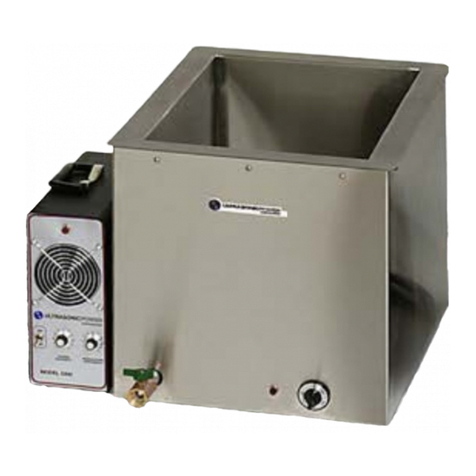
Ultrasonic UP3218 Installation instructions

Property of Ultrasonic Power Corporation - © 2018
Publication #181114 1
Operator and Maintenance Manual
UP3218- 39-GALLON ULTRASONIC CLEANING CONSOLE
UP4822- 90-GALLON ULTRASONIC CLEANING CONSOLE
UP 5424-135-GALLON ULTRASONIC CLEANING CONSOLE
UP 7028-204-GALLON ULTRASONIC CLEANING CONSOLE
Ultrasonic Power Corporation
239 E. Stephenson Street
Freeport, IL 61032, U.S.A.
Phone: 815-235-6020 • 1-800-575-0168
Fax: 815-232-2150
Email: [email protected]
www.upcorp.com

Property of Ultrasonic Power Corporation - © 2018
Publication #181114 2
Congratulations,
You have just purchased the best Ultrasonic cleaning system available to the
market today. We here at Ultrasonic Power Corporation take pride in our
products and our ability to provide you, our customer the best quality service
available. Please take some time to familiarize yourself with this manual and all
aspects of the system configuration prior to start-up. We know that your
Ultrasonic Power Corporation cleaning system will serve you for years to come.
Thank You again for selecting Ultrasonic Power Corporation for your cleaning
needs.
Sincerely,
The Ultrasonic Power Family
Find your console on page three and read the corresponding section in its
entirety. The console series of cleaning systems require special care for
proper operation. This manual gives you the education and special skills
required to operate the system at its peak performance.

Property of Ultrasonic Power Corporation - © 2018
Publication #181114 3
Table of Contents (click to use hyperlinks)
WARNINGS ....................................................................................................................4
39-GALLON BASE CLEANING CONSOLE....................................................................8
39-GALLON CLEANING CONSOLE WITH FILTRATION.............................................24
39-GALLON CLEANING CONSOLE WITH FILTRATION, WEIR AND SPARGER ......41
39-GALLON TENOR CLEANING CONSOLE WITH FILTRATION ...............................59
90-GALLON BASE CLEANING CONSOLE..................................................................76
90-GALLON CLEANING CONSOLE WITH FILTRATION.............................................92
90-GALLON CLEANING CONSOLE WITH FILTRATION, WEIR AND SPARGER ....109
90-GALLON BASS CLEANING CONSOLE WITH FILTRATION................................127
135-GALLON BASE CLEANING CONSOLE..............................................................144
135-GALLON CLEANING CONSOLE WITH FILTRATION.........................................160
135-GALLON CLEANING CONSOLE WITH FILTRATION, WEIR AND SPARGER ..177
135-GALLON CONTRA BASS CLEANING CONSOLE WITH FILTRATION..............195
204-GALLON BASE CLEANING CONSOLE..............................................................212
204-GALLON CLEANING CONSOLE WITH FILTRATION.........................................228
204-GALLON CLEANING CONSOLE WITH FILTRATION, WEIR AND SPARGER ..245
WARRANTY................................................................................................................262
RETURN OF EQUIPMENT POLICY...........................................................................266
RESHIPMENT OR RELOCATION..............................................................................268

Property of Ultrasonic Power Corporation - © 2018
Publication #181114 4
Warnings
Warning Symbols
Danger
The DANGER symbol means that failure to follow this safety statement
WILL result in personal injury or death.
Warning
The WARNING symbol means that failure to follow this safety statement
MIGHT result in personal injury or death.
Caution
The WARNING symbol means that failure to follow this safety statement
MIGHT result in personal injury or property damage.
High Voltage
The HIGH VOLTAGE symbol means that failure to follow this safety
statement MIGHT result in personal injury or death.

Property of Ultrasonic Power Corporation - © 2018
Publication #181114 5
SAFETY PRECAUTIONS
The following safety precautions should be observed when operating or servicing this
equipment.
WARNING: Utilize this equipment with accordance to the manual and good safety practices. Failure may
result in poor equipment performance, personnel injury or death, or equipment damage.
WARNING: USE ONLY WATER OR WATER-DETERGENT MIX IN CLEANING CHAMBER. NEVER USE
FLAMMABLE SOLVENTS (FIRE OR EXPLOSION COULD RESULT) OR CARBON TETRACHLORIDE
(PRODUCES TOXIC FUMES).
CAUTION: Never use ultrasonic cleaning console as a sink. Under no circumstances should waste water
be poured into it as the water could overflow the drain and damage delicate components.
CAUTION: Incorrect voltage can damage the generator. Do not operate the equipment unless the correct
voltage is available. Contact the proper authority about necessary changes at the wall receptacle.
CAUTION: Never operate unit without at least 8 inches of water in the cleaning chamber. Failure to observe
this precaution could damage the heating system.
WARNING: ALWAYS DISCONNECT ALL POWER TO THE SYSTEM PRIOR TO PERFORMING
PREVENTATIVE MAINTENANCE WITHIN THE COMPARTMENTS. ELECTRICAL SHOCK CAN CAUSE
SERIOUS INJURY OR DEATH.
WARNING: Do not operate this equipment for other than its intended use. The system is intended for
cleaning components with water and an aqueous, non-flammable, detergent.

Property of Ultrasonic Power Corporation - © 2018
Publication #181114 6
SAFETY PRECAUTIONS (Continued)
WARNING: EXTREMELY HIGH VOLTAGES, WHICH CAN CAUSE DEATH ON CONTACT, ARE PRESENT IN
ELECTRICAL CIRCUITS OF THE SYSTEM. ALWAYS USE THE FOLLOWING PRECAUTIONS WHEN
WORKING ON THE EQUIPMENT:
1. DO NOT ATTEMPT TO OVERRIDE SAFETY INTERLOCKS.
2. NEVER REACH ACROSS ANY SYSTEM WHICH HAS NOT BEEN TURNED OFF, THE PLUG PULLED AND
HIGH-VOLTAGE CAPACITORS DISCHARGED.
3. WHEN SERVICING LIVE ELECTRONIC EQUIPMENT, ALWAYS WORK WITH ONE HAND IN YOUR
POCKET OR BEHIND YOUR BACK AND STAND ON AN INSULATED PAD (e.g. RUBBER). THAT WAY IF
YOU GET SHOCKED, THE CURRENT WILL NOT PASS THROUGH YOUR BODY.
4. DON'T CARRY ON CONVERSATION OR PERMIT YOURSELF TO BE DISTRACTED IN ANY MANNER
WHILE SERVICING LIVE EQUIPMENT.
5. NEVER SERVICE LIVE EQUIPMENT UNLESS SOMEONE IS IN THE SAME ROOM WITH YOU.
6. NEVER TURN OFF THE MAIN POWER SWITCH IN SOME REMOTE SPOT AND THEN SERVICE
EQUIPMENT WITHOUT ALSO PULLING PLUG ON LINE CORD.
7. IN THE EVENT OF SHOCK, ARTIFICIAL RESPIRATION SHOULD BE APPLIED IMMEDIATELY. IF
POSSIBLE, BY A PERSON TRAINED IN ADMINISTERING SUCH TREATMENT.
WARNING: ALWAYS DISCHARGE ALL HIGH-VOLTAGE CAPACITORS BEFORE ATTEMPTING ANY
SERVICING. DON'T ASSUME THAT THE DISCHARGE FROM A CAPACITOR WILL NOT PRODUCE A
SERIOUS SHOCK. THE DISCHARGE FROM A HIGH-CAPACITY, HIGH-VOLTAGE CAPACITOR IS LETHAL!
WARNING: THE TRANSDUCERS CAN BUILD UP A CHARGE, REGARDLESS OF POWER BEING APPLIED,
DUE TO MECHANICAL SHOCK OR HEAT OF SOLUTION IN CLEANING CHAMBER. THEREFORE, TO
REMOVE SHOCK HAZARD, DISCONNECT TRANSDUCER CABLE AND SHORT THE CABLE TO GROUND
BEFORE SERVICING THE GENERATOR. USE CAUTION WHEN WORKING ON THE TRANSDUCER
ASSEMBLY.
CAUTION: Failure to reconnect wires in their original positions when replacing components in the system
may lead to failure of the system. Carefully note proper arrangement before removing wires from
components to be replaced.

Property of Ultrasonic Power Corporation - © 2018
Publication #181114 7
This equipment is intended to be utilized indoors in an ambient temperature of 50°F to 95°F.
The console systems are all protected by splashing water and debris to a rating of IP 23.
This system contains one power cord that is required to be attached to a properly rated three wire fusible
disconnect with a grounding connection capable of handling twice the rated current. The wires are
colored as follows: black - hot / ungrounded, red- return / grounded, green & yellow - protective earth. The
system also contains one drain valve for tank content drainage. The drain can be plumbed into a facility
drain or remaining unplumbed for added mobility on draining locations.
Approved hearing protection is recommended for use with this system.
Recommend the use of NRTL approved electrical plug for use with this system. Select the appropriate
plug for the voltage and current rating of the unit as per the respective national standard. When the plug is
installed, make sure the wires are cut so that the protective earth is the last to take the strain. Electrical
plugs should be installed only by a certified electrician.

Property of Ultrasonic Power Corporation - © 2018
Publication #181114 8
39-Gallon Base Cleaning Console
UP3218- 39-GALLON ULTRASONIC CLEANING CONSOLE
Table of Contents
1. SPECIFICATIONS ................................................................................................................................................. 9
2. OPERATING INSTRUCTIONS............................................................................................................................. 10
3. INSPECTION AND MAINTENANCE.................................................................................................................... 13
4. TROUBLESHOOTING......................................................................................................................................... 15
5. COMPONENT REPAIR AND REPLACEMENT ...................................................................................................... 18
6. ILLUSTRATIONS AND SCHEMATICS .................................................................................................................. 21

Property of Ultrasonic Power Corporation - © 2018
Publication #181114 9
1. Specifications
39-Gallon Base Console
Overall Width
23”
Overall Length
51”
Overall Height
40”
Tank Width
18”
Tank Length
32”
Tank Depth
16”
Working Depth
14”
Total Volume of Liquid
39 Gallons (Optimum)
Working Volume
35 Gallons
Weight (Empty)***
150 Pounds
Electrical Supply
Requirements
230V/240V-1P
50/60 Hz
Total Amperage
17 A
Ultrasonic Power (Average)
1500 Watts
Operating Frequency
40 kHz
Heater Power
2000 Watts
Estimated Heat Up Time*
3.3 Hours
Maximum dB level
86 dB
Maximum Operating Temperature**
180°F
(*) 70°F-140°F change of temperature with stainless steel lid on machine. Heat up times can be
shortened by up to 30 minutes by turning on the ultrasonics at 100% intensity.
(**) System will turn off if operated above 180˚F, liquid overtemp indicator will be on. When system
reaches below the pre-set (Pre-set at 180˚F) temperature, indicator will be turned off.
(***) Approximate weight. Subject to change. Not the same as shipping weight.
Fuse Schedule*
F1
Control Circuit Fuse
250V / 1A / FLM
F2
Control Circuit Fuse
250V / 1A / FLM
F3
Ultrasonic Generator Fuse
250V / 10A / FLM
F4
Ultrasonic Generator Fuse
250V / 10A / FLM
F5
Heater Fuse
250V / 10A / FLM
F6
Heater Fuse
250V / 10A / FLM
(*) Only trained personnel, not the operator, should replace the fuses
(**) All fuses are slo-blow time delay

Property of Ultrasonic Power Corporation - © 2018
Publication #181114 10
2. Operating Instructions
2.1. General
The following instructions are intended to guide the user when: (1) instructing operators
in techniques designed to ensure optimum equipment performance; and (2) verifying
the validity of operator complaints. See Section 4 - Troubleshooting, if the console is
not operating properly.
2.2. Before Operating this Equipment
1. Ensure that the liquid level is at an appropriate height as to not to damage the
heaters. Minimum level is 8 inches.
2. Check for leaks in the plumbing for a precautionary measure before adding
chemicals.
3. Plug the power cable into the appropriate voltage outlet. Using incorrect voltage will
not allow the cleaner to operate properly and may damage the system.
2.3. Operating the Equipment
1. Getting Started - Locate the unit on a solid and level surface. If you are filling the
unit with a hose be sure the customer provided disconnect switch is in the off
position prior to filling the machine to avoid splashing the internal electrical
components.
2. Filling the Unit - Check to be sure the drain valve is tightly closed. Fill the tank up
to the recommended working level with high quality water. If tap water is not of good
quality, it is recommended that filtered water is used to allow the detergent to
perform at its highest level. Optimum water temperature will vary as some
chemicals will require higher temperatures for proper cleaning.
3. Set Heater temperature –For most industrial applications, 140F is the
recommended fluid temperature. Some applications or detergents will require other
temperatures and may be as low as 90F. Consult your sales representative if you
do not know what temperature to set the unit to.
4. Adding Chemicals –Use the mixture rate recommended by the detergent
manufacturer. After cleaning one or two items, you may choose to increase the
chemical ratio. The amount of chemical will be based on the condition of the water
being used and how much contamination is to be removed. Detergents that are
used in this ultrasonic cleaning system must be compatible with 304 and 316L
stainless steel. You will void the warranty if chemical attack to the stainless
steel occurs.

Property of Ultrasonic Power Corporation - © 2018
Publication #181114 11
5. Power On –Turn on the ultrasonic start switch. The ultrasonic generators will start
the ultrasonic action in the tank. All installed generator circuits are controlled by one
switch on the control panel. The power intensity should be set to 80% and adjusted
after testing parts. If UPC performed a cleaning test, consult the test report or
contact your sales representative.
6. System Degassing -If new water and detergent has been added allow the system
to run through one cycle. This allows the water in the cleaning tank to properly
degas (the water comes to oxygen equilibrium). The de-gassing process removes
unwanted air molecules from the cleaning tank, thus maximizing the efficiency of
the cavitation/cleaning process.
7. Liquid Overtemp Protection –The liquid overtemp protection’s primary purpose is
to turn off the system when operated above 180˚F. When the system is operated
above 180˚F, liquid overtemp indicator will turn on. Liquid overtemp indicator will
stay on until the system reaches below the pre-set (Pre-set at 180˚F) temperature.
Contact UPC if system does not turn on when temperature reaches below the pre-
set temperature.
8. Cleaning - Place materials to be cleaned into the cleaning tank. Be sure that all
parts and components are fully submerged into the cleaning solution. Check to be
sure that no air pockets are present on the item(s) being cleaned, as the cavitation
process will only be effective where water contacts the part’s surface. It may be
necessary to rotate the part while submersed to allow air to escape. Some initial
testing will help determine the proper settings for the optimum time and
temperature. For most applications, due to the extreme efficiency
of the unit, only 2 to 3 minutes of immersion time is required to thoroughly clean the
average part. These applications include removing machining oils and small
particles. For application involving baked on carbon or calcium and mineral
deposits, longer times and higher temperatures may be required.
When first learning the capabilities of this system, do no leave items
unattended in the wash tank for long periods. The system may damage
surfaces if allowed to remain in the ultrasonic bath for extended periods of
time. Longer cleaning times can be used after thorough testing has been
completed.
Do not place items to be cleaned directly on the tank bottom. The bottom is
essentially a high frequency speaker so contact may hinder the acoustic
propagation. Use UPC approved baskets or fixtures that are designed to minimize
acoustical losses and or damage to the tank bottom and the transducers. Heavy
items should always be suspended or placed on a work rest. In cases when a work
rest is required, consult UPC regarding a proper design for your application.

Property of Ultrasonic Power Corporation - © 2018
Publication #181114 12
Do not attempt to clean aluminum in a caustic solution.
Do not use any chemical that is combustible. Chemicals not approved by UPC may
void warranty. Consult with UPC if unsure.
Do not use bleach or ammonia as a cleaning chemical.
2.4. At the End of Each Day
1. Turn the heater switch to the "OFF" position.
2. Turn the main power switch to the "OFF" position.
3. Wipe off the machine to remove excess dirt and water.

Property of Ultrasonic Power Corporation - © 2018
Publication #181114 13
3. Inspection and Maintenance
3.1. General
The maintenance described in this section should be performed at best intervals
determined by the usage of the equipment, unless otherwise indicated. Should a
problem occur when operating the unit, refer to Section 4, Troubleshooting. If a policy
requires for calibration of the unit, the generators would be the only calibrated items that
UPC recommends calibrating. They may be sent back to Ultrasonic Power Corporation
for calibration on an annual basis. Please request an RMA number before shipping the
generators back to the manufacturer.
3.2. PERFORMANCE VERIFICATION
1. Check installation requirements against specifications in Section 1.
Also:
a. Inspect overall unit for signs of damage or misaligned parts.
b. If applicable, make sure leveling feet are adjusted to fit the floor.
c. If applicable, make sure the castors are locked in place to prevent
movement of system during operation.
d. Be sure all side panels are in place on the system.
NOTE: All side panels must be installed prior to operation to allow for
proper airflow to the system. This also protects the operator from potential
shock.
2. Check input voltage at the wall receptacle. The voltage at the wall
receptacle must be the same rating for the system for the system to
operate properly. Make sure system is grounded properly or erratic
operation may occur with optional Sonic Touch control panel.
Caution: Incorrect voltage can damage the generator. Do not
proceed unless the above voltage readings are obtained. Contact the
proper authority about necessary changes at the wall receptacle.
3. Enable the power switches for each sub-system to check their operability.
a. ULTRASONICS- Enable the ULTRASONICS power switch. Rotate the
power intensity control (PIC) clockwise to increase the cleaning action.
Sound from transducers should increase/ decrease and you should
visually see ripples in the liquid.

Property of Ultrasonic Power Corporation - © 2018
Publication #181114 14
CAUTION: Never turn on the system without having at least 8” of
liquid in the tank or damage to the heating system will occur.
b. HEATER - Enable the HEATER switch. Over time, the liquid will heat
up. Estimated heat up time from 70°F –140°F is 3.3 Hours
* Turning on the ultrasonics during heat up will shorten heating time.
3.3. Preventative Maintenance
WARNING: ALWAYS SET BUILDING ELECTRICAL-SUPPLY
DISCONNECT SWITCH AND CLEANER MASTER POWER SWITCH AT
"OFF", OR DISCONNECT POWER CORD FROM WALL RECEPTACLE,
BEFORE PERFORMING ANY PREVENTATIVE MAINTENANCE
FUNCTIONS WITHIN ANY COMPARTMENTS. ELECTRICAL SHOCK
CAN CAUSE SERIOUS INJURY.
Recommended maintenance cycle is 3 months.
1. Wash chamber interior with mild detergent. Rinse with tap water using a
sponge or damp cloth. Dry with a lint free cloth.
2. Clean exterior of system with stainless steel cleaner.
3. Remove side panels and clean interior of system with compressed air.
Caution: Do not use liquid to clean the interior of the system. Electric
shock may occur.

Property of Ultrasonic Power Corporation - © 2018
Publication #181114 15
4. Troubleshooting
Only trained personnel are allowed into the inside of the machine.
4.1. GENERAL
This section contains detailed information for locating and correcting malfunctions. The
following steps provide an effective approach to the use of this information in
conjunction with other areas of the manual. If possible, consult with the operator who
used the Cleaner last. Find out what happened just before the trouble started and
indicated that a problem existed. Check to be sure that the system has the minimum
specified level of water in the cleaning tank and that the system has power prior to
troubleshooting.
4.2. PRINCIPLES OF OPERATION
Ultrasonic cleaning systems employ high frequency, mechanical vibrations transmitted
into and through a suitable cleaning liquid where the cleaning action takes place. High
frequency or ultrasonic vibrations are similar to audible sound, but the frequencies used
are generally above a level that can be heard (>18 kHz). Since sound is a compression
wave, the action of this high frequency energy in a liquid may be considered as the
rapid generation and violent collapse of minute bubbles. Countless small but intense
impacts erode surface soil from immersed parts. This action (cavitation) wears away
surface contamination...it does not "shake off the dirt".
An ultrasonic cleaning system consists of the following components:
1. An ultrasonic generator capable of producing high frequency electrical energy.
Ultrasonic Power Corporation utilizes our 5300 series generator.
2. Vibra-bar®transducer technology to convert electrical energy received from the
generator into mechanical energy.
a. Transducers fall into two main classes: Piezoelectric (electrostrictive) and
magnetostrictive. In the first instance, a material changes dimensions in the
presence of an electric field is utilized; in the second instance, the material is
influenced by a magnetic field (causes it to vibrate). Ultrasonic Power
Corporation uses the Piezoelectric (electrostrictive) transducers with its
generators.
3. A tank to contain the cleaning liquid (water-detergent mix) and into which the
mechanical (ultrasonic) energy is transmitted by the transducers.
a. Use of a suitable detergent is important because the liquid that transmits the
energy from the transducers also participates in the cleaning process: (1) the
mechanical action (cavitation), and (2) by solvent action, physical wetting or
chemical attack on surface soil.
4. The Heater pads are affixed to the sides of the tank. The heater controls are located
on the control panel.

Property of Ultrasonic Power Corporation - © 2018
Publication #181114 16
4.3. HOW TO USE TROUBLESHOOTING CHARTS
1. Select the proper Table.
2. Refer to Problem and select example you think most appropriate for your
particular trouble symptom. Examples are presented in cycle sequence.
3. Perform a mechanical and electrical checkout of components to designate under
ITEMS TO CHECK. Note the following:
a. Examine electrical as well as mechanical component for signs of damage
and loose or misaligned parts.
b. When applicable, use the schematic component designation and the
appropriate schematic to determine the circuit and component function.
Correct all loose wires or improper connections.
4. When troubleshooting is complete, replace defective items, restore circuits to
normal and reinstall removed items

Property of Ultrasonic Power Corporation - © 2018
Publication #181114 17
4.4. Troubleshooting Table
Only trained personnel are allowed into the inside of the machine.
PROBLEM
ITEMS TO CHECK*
1. System does not receive
power when "Main Power"
switch is turned to "ON" position.
a. Unit Power Cord
b. Building Power Supply
c. Unit’s Fuses
d. Loose/ disconnected wires
e. Switches
PROBLEM
ITEMS TO CHECK*
2. The Ultrasonics do not work.
a. Building Power Supply
b. Unit’s Fuses
c. Loose/ disconnected wires. Broken wires may result in changes to
the transducer capacitance
d. Capacitance of BNC Connector to Generator is at least 20 nF.
e. Switches and Settings
PROBLEM
ITEMS TO CHECK*
3. The Heater does not work.
a. Building Power Supply
b. Unit’s Fuses
c. Loose/ disconnected wires
d. Amperage is near 4.1A per 1000W’s
e. Switches and Settings
(*) Where applicable, the component schematic for a console model follows the component description.
If the problem has not been solved using the trouble shooting guide, call the Ultrasonic
Power Corporation service department at (815) 235-6020 7:00 AM - 3:30 PM CST Monday -
Friday.

Property of Ultrasonic Power Corporation - © 2018
Publication #181114 18
5. Component Repair and Replacement
Only trained personnel are allowed into the inside of the machine.
5.1. GENERAL
This section includes instructions for the adjustment, disassembly, repair and
replacement of selected components. Illustrations showing the various parts and
assemblies, as well as their associated part numbers, referred to in this Section are in
Section 6.
WARNING: EXTREMELY HIGH VOLTAGES, WHICH CAN CAUSE
DEATH ON CONTACT, ARE PRESENT IN ELECTRICAL CIRCUITS OF
THE ULTRASONIC SYSTEM. ALWAYS USE THE FOLLOWING
PRECAUTIONS WHEN WORKING ON THE EQUIPMENT:
1. NEVER REACH ACROSS A SYSTEM WHICH HAS NOT BEEN
TURNED OFF, THE PLUG PULLED AND THE HIGH-VOLTAGE
CAPACITORS DISCHARGED.
2. WHEN SERVICING LIVE ELECTRONIC EQUIPMENT, ALWAYS
WORK WITH ONE HAND IN YOUR POCKET OR BEHIND YOUR
BACK AND STAND ON AN INSULATED PAD (e.g. RUBBER).
THAT WAY, IF YOU DO GET SHOCKED, THE CURRENT WILL
NOT PASS THROUGH YOUR BODY.
3. DON'T CARRY ON CONVERSATION OR PERMIT YOURSELF TO
BE DISTRACTED IN ANY MANNER WHILE SERVICING LIVE
EQUIPMENT.
4. NEVER SERVICE LIVE EQUIPMENT UNLESS SOMEONE IS IN
THE SAME ROOM WITH YOU.
5. NEVER TURN OFF THE MAIN POWER SWITCH IN SOME
REMOTE SPOT AND THE SERVICE EQUIPMENT WITHOUT
ALSO PULLING PLUG ON LINE CORD.
6. IN THE EVENT OF SHOCK, ARTIFICIAL RESPIRATION SHOULD
BE APPLIED IMMEDIATELY. IF POSSIBLE, BY A PERSON
TRAINED IN ADMINISTERING SUCH TREATMENT.

Property of Ultrasonic Power Corporation - © 2018
Publication #181114 19
5.2. MODEL 5300 GENERATOR
NOTE: Use the following procedure whenever the generator is not operating properly.
Do not attempt to do more than is listed below as it may void the warranty.
1. Remove power from the system.
2. Check fuses (on control panel and on back of
generator), replace if necessary.
3. Check for loose connection of wires.
4. Check supplied power for correct voltage
specifications.
5. Test generator by turning the system on.
6. If generator does not work, contact Ultrasonic Power Corporation service
department for repair or replacement.
NOTE: DO NOT open the generator as this will immediately void the warranty of the
generator.

Property of Ultrasonic Power Corporation - © 2018
Publication #181114 20
5.3. VIBRA-BAR®TRANSDUCER PACK
1. Remove power from the system.
2. Check transducer stacks for damage and loose
wires.
3. If damage is visible or capacitance is low, contact
Ultrasonic Power Corporation service department for repair
or replacement.
5.4. HEATERS
1. Remove power from the system.
2. Check heater fuses located on the inside of
the control panel.
3. Check heater pad for proper contact with the system tank.
4. Check for loose or damaged wires.
If damage is visible, contact Ultrasonic Power Corporation service department for repair
or replacement.
This manual suits for next models
3
Table of contents
Other Ultrasonic Cleaning Equipment manuals

Ultrasonic
Ultrasonic 6000FLT Quick start guide

Ultrasonic
Ultrasonic BT SE Series User manual

Ultrasonic
Ultrasonic BT2424/Alto User manual

Ultrasonic
Ultrasonic BT H Series User guide

Ultrasonic
Ultrasonic Ultra 3800FLT Quick start guide

Ultrasonic
Ultrasonic Digital Pro Ultra 2100 User manual

Ultrasonic
Ultrasonic BT H Series User manual