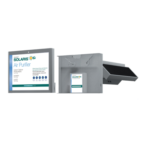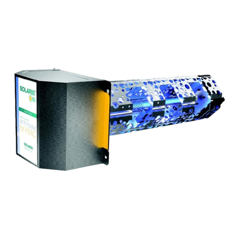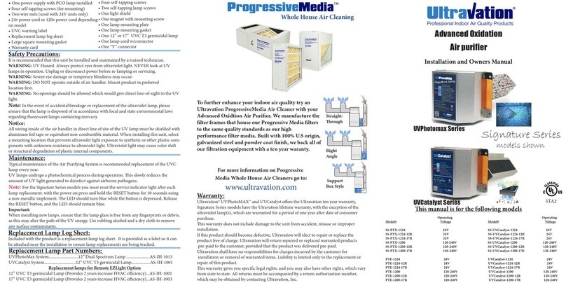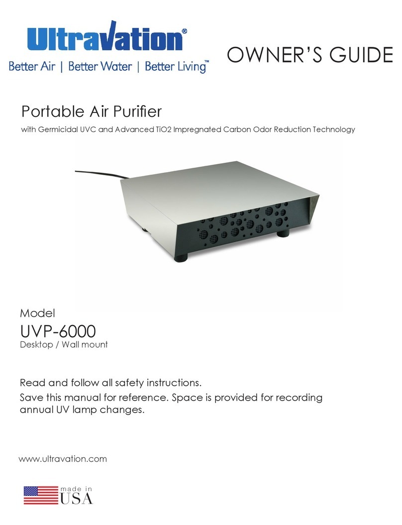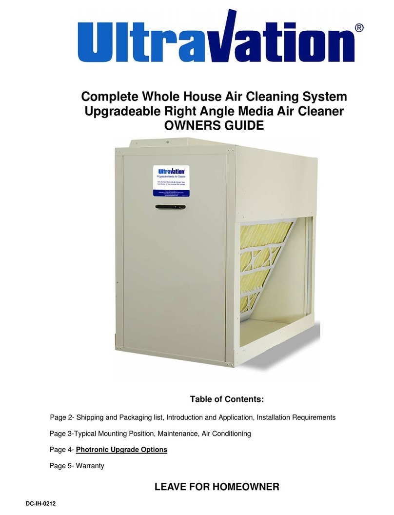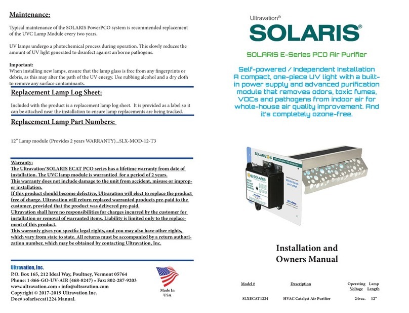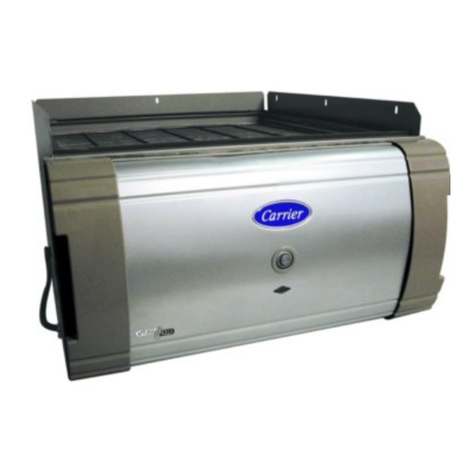
• Solaris EUVCat/ UVCat purifer
• Four self tapping screws
• Two wire nuts
• 24VAC Power cord
• UV Lamp (installed)
• Warranty card
• warning/ lamp replacement card
• Product gasket
Package Contents:
UVGI lamp replacement procedure:
To replace the module follow the steps below:
1. Unplug power cord, remove two screws from housing pull to unplug
power module.
2. Remove two lamp screws (do not discard screws).
3. Install newlamp with care not add any nger prints to glass sleeve.
5. re-install the module with two screws.
6. plug power cord in, repplay power.
7. UVCat series only with power on depress reset button for 10 seconds.
Electrical installation
is product operates on 24 VAC must be connected to a dedicated minimum 40va trans-
former .
1. Disconnect power supply before beginning installation to prevent electrical shock or
equipment damage.
2. Connect secondary voltage. Refer to voltage color or terminal coding on transformer
for proper wire combination. On terminal type transformer, be sure that no exposed wire
can come in contact with any terminal.
3. Connect primary voltage. Refer to voltage color coding on transformer for proper wire
combination.
4. Tape or protect all unused exposed wire separately to avoid a possible electrical short.
5. Check installation and reconnect power supply for proper operation.
6. Connect 24 VAC wires to supplied 6 cable (polarity not important)
Position
Actuators
Closed
Position
Actuators
Open
e PCO Panels ship in the closed position. Only open for operation aer
mechanical installation. Never move the panels by hand only use the actuatorsNever move the panels by hand only use the actuators
Optional accessory sold seperatly
p/n: 94-135
e Solaris UVCat series has onboard disagnostics
to determine lamp failure and lamp replacement
requirement. A visual blue LED indicates normal
operation , red indicates service is required. rember
to press the reset button for 10 seconds aer each
lamp change (UVCat models only). also equpped
with an audiable alarm for any faults
Installation Steps:
1. Determine a suitable location to install the module. Mounting location should be of
sucient strength as to support the module; otherwise reinforcement of the ductwork
may be necessary. e module should be installed aer ltration and before any branch-
es in the ductwork.
2. When a suitable location is determined drill a 4” hole for installation of the module.
3. Make sure to remove protecive bag from around lamp used for shipping purposes.
4. Ensure catalyst position actuator is in the closed position (as shown
to the right.) Attach square mounting gasket (supplied) to the bottom
of the module. Li module, place against ductwork. Fasten module in
place with four self-tapping screws (supplied) in lower and upper
mounting positions.
5. Once installed push in and relocate the catalyst actuators to the
open position (as shown to the right).is ensures you maxamize the
surface area of titanium infused carbon to allow you to acheive
maximum performance.
6. Turn o power to system being upgraded by turning o, disconnect
or turning o breaker to the system.
7. Plug the lamp connector fully onto the installed UVCatalyst lamp. Be sure the four
pinholes are orientated properly to the four matching pins on the lamp.
is product can be
converted to 120 volt
(line voltage)
e E-UVCat series has 2 LED indicators. Green
operation is normal. Red indicates the need for
service.
is product is 6-P compatable
allowing it to operate a
second UVC lamp for additional
purication
(sold seperatly)
