Unic Stella Epic Specification sheet

1
TECHNICAL NOTE
Thank you for choosing UNIC, the leading French manufacturer of
professional espresso machines since 1919.
The manufacturer reserves the right to modify the
appliance presented in this publication without
notice in order to improve its performance.
Read the safety instructions carefully before use.
SE9011 07/2019


3
Table of contents
►Safety instructions...............................................................................................................................5
⌂INSTALLATION...........................................................................................................................6
►Preparing the machine ........................................................................................................................6
♦Unpacking the machine.................................................................................................................................... 6
♦Preparing the site and installing the machine................................................................................................ 6
►Water connection.................................................................................................................................6
►Electrical connection...........................................................................................................................7
♦Electrical connections ......................................................................................................................................7
♦Connection diagrams........................................................................................................................................7
► Verication of the toroidal transformer with respect to the mains voltage....................................8
►Starting up ............................................................................................................................................8
♦Filling the boilers...............................................................................................................................................8
♦Steam boiler ........................................................................................................................................................8
♦Unit boilers...........................................................................................................................................................9
♦Heating ...............................................................................................................................................................9
►Checks & adjustments.........................................................................................................................9
♦Temperature setting..........................................................................................................................................9
♦Adjusting the expansion valve.........................................................................................................................9
♦Adjusting the pump pressure......................................................................................................................... 10
♦Adjusting the water inlet solenoid valve....................................................................................................... 10
♦Adjusting the coee grinding.........................................................................................................................10
♦Adjusting the mixer tap for hot water............................................................................................................10
♦Adjusting the basin......................................................................................................................................... 10
⌂USE & PROGRAMMING ..........................................................................................................11
►Interface .............................................................................................................................................. 11
♦Description of the 4 dose BGX menu.............................................................................................................11
♦Description of the Dosamat BGX menu .........................................................................................................11
♦Description of the BTA menu .........................................................................................................................12
♦Various icons.....................................................................................................................................................13
►Main menu ..........................................................................................................................................14
►Day/night programming.....................................................................................................................15
►Counters .............................................................................................................................................15
►Settings...............................................................................................................................................16
►Other settings.....................................................................................................................................17
►Use ...............................................................................................................................................18
►Cleaning..............................................................................................................................................19
►Maintenance .......................................................................................................................................20
►Details of settings menu....................................................................................................................21
♦Language..........................................................................................................................................................21
♦Choice of language............................................................................................................................................21
♦Customisation..................................................................................................................................................21
♦Choice of type of keyboard................................................................................................................................21
♦Screensaver ......................................................................................................................................................21
♦CIM.................................................................................................................................................................... 21
♦Saving...............................................................................................................................................................22
♦Levels of access.............................................................................................................................................. 22

4
►Details of Other settings menu.........................................................................................................23
♦Probe calibration............................................................................................................................................. 23
♦IT connection................................................................................................................................................... 23
♦Connectivity..................................................................................................................................................... 23
►Details of Use menu...........................................................................................................................24
♦Hot water & steam........................................................................................................................................... 24
♦Dosamat ...........................................................................................................................................................24
♦Infusion proles...............................................................................................................................................24
♦Standard mode..................................................................................................................................................24
♦Expert mode......................................................................................................................................................25
⌂MAINTENANCE & REPAIRS...................................................................................................27
►Cleaning..............................................................................................................................................27
♦After each use..................................................................................................................................................27
♦Steam outlet tube ..............................................................................................................................................27
♦Daily.................................................................................................................................................................. 27
♦Before use or after several hours of inactivity: .................................................................................................. 27
♦After the service.................................................................................................................................................27
♦Weekly.............................................................................................................................................................. 27
♦Filter holder cup.................................................................................................................................................27
♦Basin..................................................................................................................................................................27
♦Bodywork...........................................................................................................................................................27
► Details of the coee cleaning Procedure menu ..............................................................................28
♦Coee rinsing ..................................................................................................................................................28
♦Coee cleaning................................................................................................................................................ 28
♦Reference of cleaning products.........................................................................................................................28
♦option SteamAir.............................................................................................................................................. 29
♦Components......................................................................................................................................................29
♦key SteamAir .................................................................................................................................................... 29
♦Programming.....................................................................................................................................................29
►Details of the Maintenance menu .....................................................................................................30
♦Components test............................................................................................................................................. 30
♦Softener............................................................................................................................................................ 30
♦Descaling..........................................................................................................................................................30
♦Machine cooling ..............................................................................................................................................31
♦Error log ...........................................................................................................................................................31
►Repairs ...............................................................................................................................................32
♦Troubleshooting.............................................................................................................................................. 32
♦Technical features...........................................................................................................................................32
♦CPU connectors & fuses.................................................................................................................................33
♦Cable lists.........................................................................................................................................................34
♦Plate assembly.................................................................................................................................................36
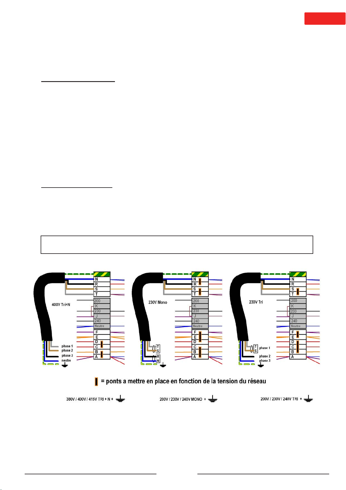
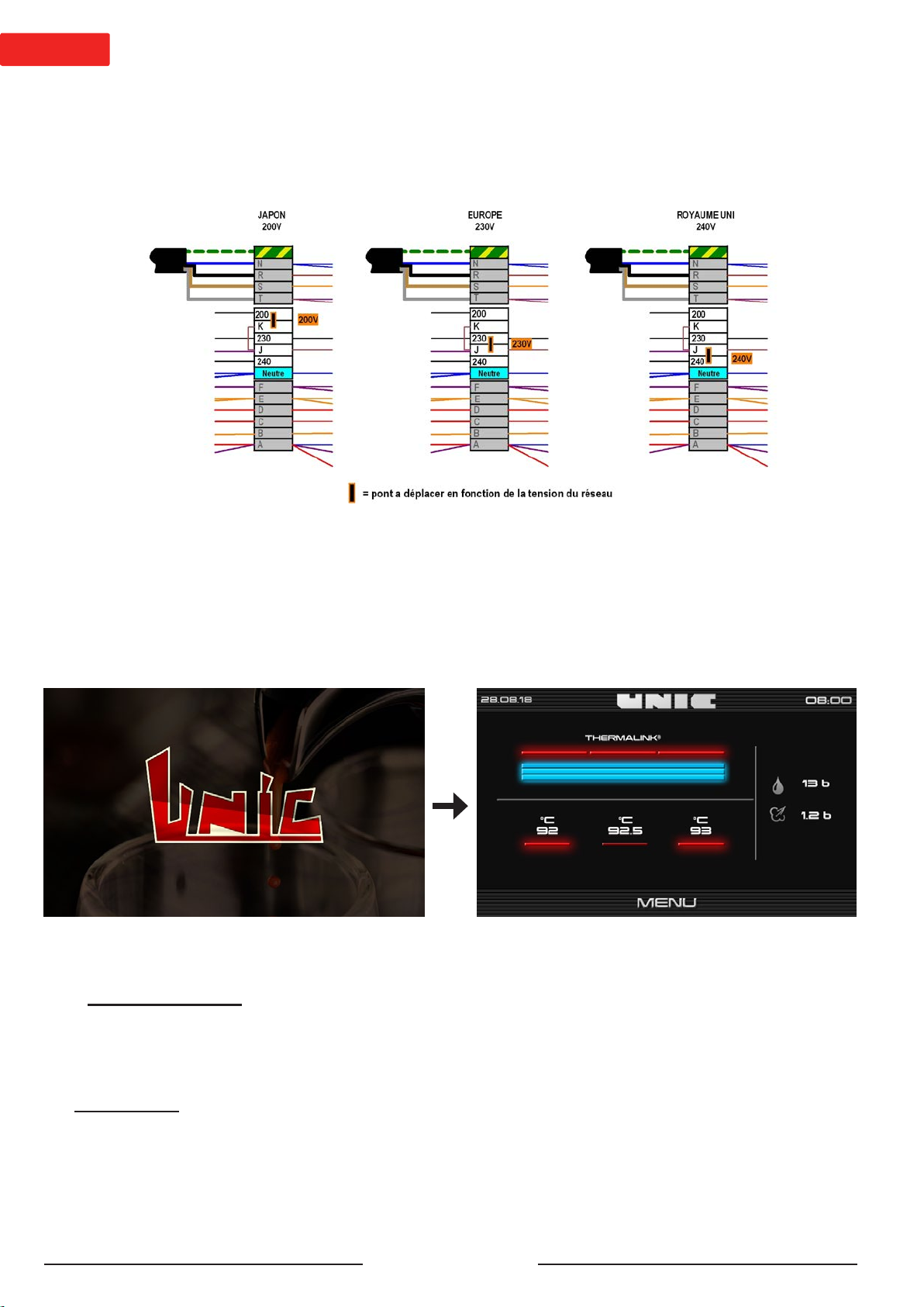
♦Wiring diagrams .............................................................................................................................................. 37
♦Procedure for updating the machine.............................................................................................................40
♦Assembly/replacement procedures...............................................................................................................42
♦Mother board replacement (CPU) .....................................................................................................................42
♦BTA/BGX/BST box replacement........................................................................................................................42
♦Cup seal............................................................................................................................................................43
♦List of error codes........................................................................................................................................... 44

5
►Safety instructions
This appliance is intended to be used only for its specic use.
The manufacturer disclaims any liability for damage caused by abnormal use or abuse.
Children 8 years of age or older and persons with reduced physical, mental or sensory abilities, or lack of
experience and skill may use this appliance, if supervised by a qualied person, or they have received the
instructions for use and safety necessary to understand the risks involved.
Supervise children to make sure they do not play with the appliance; they must not be allowed to clean or
maintain it.
Do not leave packaging elements within reach of children. These elements are potentially a source of danger.
The installation must be done by a qualied technician and following local and national regulations. They are
the only people authorised to access the internal parts of the appliance for maintenance and repair.
Only use the technical and spare parts manuals to ensure correct operation of the machine, and do not
compromise safety.
Access to the service area is restricted to persons with the necessary knowledge of safety and hygiene as
well as practical experience of the appliance.
Leave enough space around the machine for easy use and access if any repair intervention is required.
The appliance must not be:
- exposed to elements of the external environment or placed in damp places,
- exposed to a water jet or splashing.
- installed in areas where jets or high pressure cleaners are used.
The appliance must be:
- placed on a stable, level and horizontal surface
- used at ambient temperature of 5°C to 35°C (41°F - 95°F), (if it is stored at an ambient temperature below
5°C (41°F), the water circuit (boiler-piping) must be drained).
- if the appliance freezes, wait 24 hours at a minimum temperature of 10°C (50°F) before restarting it.
Before connecting the power and water supplies, check that the electrical and water mains comply with the
technical information plate of the appliance.
The power supply must be provided with the following safety features: power switch which completely isolates
the machine from the mains (gap between contacts of at least 3 mm), ecient earthing and an eective circuit
breaker for protection against earthing leaks; section of the conductors appropriate for a power capacity.
Before connecting or disconnecting the power cable, switch the main switch to position 0.
If the power supply cable is damaged, it must be replaced by the manufacturer, by its after-sales service
technician or similarly qualied persons, to avoid any danger.
For electrical safety, make sure that the appliance is properly earthed.
The manufacturer disclaims any liability for damage caused by improper earthing.
The appliance must be connected to the water mains with a pressure of 1 to 8 bar (0.1 to 0.8 MPa) and a tap
readily accessible must be tted in front of the water supply tube.
The appliance is to be installed with adequate backow protection to comply with applicable federal state and
local codes.
In case of an emergency (re, surge, abnormal noise, etc.), the rst thing to do is to cut o the power supply
and close the water tap.
Be careful not to obstruct the air inlets of the machine with cloths or other objects.
Beware of hot surfaces such as cup warmers, the unit heads and the hot water and steam outlets.
Never place containers lled with liquids on top of the machine
Never expose it to hot water or steam jets.
The machine should be descaled only by a qualied technician.

6
►Preparing the machine
The machine is delivered in a cardboard box and is screwed onto a wooden pallet.
♦Unpacking the machine
- Cut the strapping.
- Open the crate and take out the box containing the accessories.
- Unscrew the nuts securing the machine to the pallet.
- Separate the cardboard box from the pallet.
- Remove the machine from the pallet and place it on wooden blocks.
- Remove the transport screws and washers.
♦Preparing the site and installing the machine
- Position the machine in its denitive location.
- The machine must be installed on a at surface.
- It is necessary to leave a space of 5 cm at the back. Do not obstruct the air intakes provided on the top of
the machine.
- An earthed electrical socket corresponding to the characteristics of the machine and a water supply are
sucient.
(The machine must not operate without its feet)
►Water connection
A water softener is essential above 5° KH
Water inlet:
- Pressure: 1 - 8 bar (0.1 MPa - 0.8 MPa).
- Fitting: 3/8 female gas (male tting on the machine).
- Tube: internal diameter 8 mm minimum.
- Provide a shut-o tap.
Intervention underneath the machine at the centre:
Screw the water inlet tube onto the tting in the machine (photo
opposite).
Draining:
- Fitting: Ø18 mm female (at the back of the basin)
- Tube: internal diameter 12 mm minimum.
- Fitting: Ø12 mm female (on the bottom of the machine in the centre)
- Tube: internal diameter 10 mm minimum.
The drain tube is supplied tted on the machine.
Then connect the other end of the drain tube to a waste water drain by
ensuring that no adverse slope interferes with good outow.
NOTE: The tube with the smallest diameter must not include a goose
neck.
⌂INSTALLATION

7
1 = GREY PHASE
2 = BROWN PHASE
3 = BLACK PHASE
INALL CASES THE GREEN/YELLOW WIRE MUST BE CONNECTED TO THE EARTH OF THE
INSTALLATION
►Electrical connection
- None of the switches on the machine must be left on.
- Check that the values of the voltage, frequency and power shown on the technical information plate of the
appliance match those of the mains.
♦Electrical connections
IMPORTANT: The machine must be connected to a line tted with a general cut-o.
The machine is delivered with a cable of 5 numbered wires.
Set the general cut-o to 0 before the intervention.
Check that the wiring of the machine matches the available mains voltage, in accordance with the connection
diagrams below. If necessary, modify by working on the jumpers on the terminal block located on the left-hand
side of the machine.
IMPORTANT:
Connection to 230 V with 5-strand cable, it is necessary to couple the wires at the end of the cable correctly.
Single-phase 230V connection: blue and black wires together, brown and grey wires together. Watch the
amperage (32 A)
Connection in 230V 3-phase: brown and grey wires together. Important: there is no neutral so the blue wire
must be connected to a phase
♦Connection diagrams

8
►Starting up
When the machine is switched on, it runs an initialisation that checks all components. The start-up time lasts
about 45 seconds.
♦Filling the boilers
- Open the water shut-o tap
- Connect the mains electric plug.
- Turn the switch to the ON position.
♦Steam boiler
When the switched on, the lling is done automatically.
A safety mechanism is provided if the lling is not done within 3 minutes. In this specic case, the solenoid
valve for lling and the pump cut o.
Start-up screen Control screen
►Verication of the toroidal transformer with respect to the mains voltage
The machine has a multi-voltage transformer to guarantee the right mains voltage for the electronics.
The machine is factory-tted according to the destination country.
E.g.:
Should it be necessary to modify the factory assembly, it is only necessary to intervene on the jumpers: no
cables need to be displaced.

9
►Checks & adjustments
Usually, the adjustments are made before leaving the
factory. Check that these adjustments are correct and, if
necessary, change them, proceed as follows for access:
It is necessary to remove the right side of the machine:
Loosen the 3 mm BTR screws a few rotations at the bottom
of the machine (1), between the two straight feet.
Use the suction pad (2) to remove the side by tipping it (3)
upwards.
(Be careful to support the element which is heavy!)
♦Temperature setting
The temperature of each unit and the steam boiler are
adjusted independently from the control screen in the “Use”
menu. (See p:24)
♦Adjusting the expansion valve
The valve is on the front right-hand side of the machine
It can be adjusted the control screen
The valve must open at about 13 bar during heating
Use a lug wrench (ref.: OU003).
- If it opens ABOVE 13 bar: UNSCREW
- If it opens BELOW 13 bar: SCREW IN
After this adjustment, do not forget to block the lock-nut.
- Check the machine’s water supply.
- Shut down and restart the machine by turning the switch to OFF then ON.
- The lling starts again for 3 minutes.
♦Unit boilers
A small quantity of water needs to ow from each unit.
If not, the upper keys of the default unit ash:
Check the machine’s water supply.
- Shut down and restart the machine: turn the switch to OFF then ON.
Relling starts again.
♦Heating
Heating of all elements starts automatically if correctly lled. When the operating temperature of the machine
is reached, the machine is operational.
The steam pressure and temperature of the units are visible on the screen.
It is advisable to leave the machine heating permanently on and leave the lter holders engaged onto
the machine when not infusing.
The menu is not accessible as long as the machine is not hot. Once the machine is hot, just press the screen
to access the menu.
1
2
3

10
♦Adjusting the pump pressure
When infusing, the pressure must be 9 to 10 bar (0.9 MPa et 1 MPa),
display on the control/settings screen.
The pump is located on the right-hand side of the machine and is
adjusted on this same side.
SCREW to INCREASE pressure,
UNSCREW to REDUCE pressure,
♦Adjusting the water inlet solenoid valve
The water inlet solenoid valve is on the right-hand front of the machine.
It is accessed from the front of the machine.
When the machine has reached its operating temperature, start a
cycle (with coee) continuously on each unit simultaneously.
Induce the boiler to ll up (by drawing hot water).
Adjust the maximum ow rate of the solenoid valve so as not to fall
below 7 bar (0.7 MPa).
Then check that the lling time of the boiler is not excessive.
♦Adjusting the coee grinding
Wait until the machine has reached the set temperature 0.9 to 1 bar (0.09 MPa to 0.1 MPa).
The coarseness of the grinding determines the time needed for hot water to pass through the dose. This time
is usually controlled by using the two-cup lter with two doses of coee.
Average time to make 2 cups (6 to 7 cl. per cup): 30 to 35 seconds.
- If this time is shorter, reduce the grinding coarseness.
- If this time is too long, increase the grinding coarseness.
To obtain a good result, use at least 6 g of (good) ground coee per cup.
♦Adjusting the mixer tap for hot water
The mixer tap is located on the top, on the right-hand front of the machine. To adjust it, it is necessary to
remove the right side.
The temperature range is approximately 55°C to 95°C (131°F à
203°F), to adjust the required temperature, use a at screwdriver. The
adjustment is done on the cold water solenoid valve (if it is not already
open, open the hot water solenoid valve to its maximum).
Always make adjustments during the hot water cycle.
If you make adjustments without drawing any hot water, as the water
is incompressible, you could damage the elements of the water circuit.
SCREW to INCREASE the temperature
UNSCREW to REDUCE the temperature
♦Adjusting the basin
On the Stella EPIC range, the basin can be adapted to the products
required by the user.
5 positions possible, clearance of 115 mm maximum.
The adjustment is done manually by two triggers located below on the
sides of the basin.
85 mm
200 mm

11
⌂USE & PROGRAMMING
►Interface
♦Description of the 4 dose BGX menu
♦Description of the Dosamat BGX menu
Start key (free mode)
Pre-infusion key (free mode)
Stop key (free mode)
Free infusion
prole mode zone
Screen
Selection of an
expert prole
Dosed classic key
zone
Start key (free mode)
Pre-infusion key (free mode)
Stop key (free mode)
Free infusion
prole mode zone
MAN key, manual start Coee keys SELF key, automatic start
Screen
Selection of an
expert prole
Dosamat key zone
(option)

12
Coee boiler
heating element
Steam boiler heating element 1 to 3
Steam pressure
Machine’s water
network pressure
Coee heater
temperature
Steam boiler
level
Real-time information
relating to the whole
machine
Rapid access to the “Cleaning” menu Back to the main
screen
Access to levels 1 & 2
with password
Key to put the machine
into standby mode
♦Description of the BTA menu

13
♦Various icons
Icon to access the “rapid access/code” screen
Back to the main screen
Back to the previous page
Icon to copy a le and/or data
Icon to indicate parameters (e.g.: steam settings)
Icon to save data and/or settings
Icon to conrm data and/or settings
Icon to cancel data and/or settings
Icon to access enabled error codes / alarms.

14
Maintenance p.20
Day/night programming p.15
Counters p.15
Main menu
Use p.18
Cleaning p.19
Other settings p.17
Settings p.16
►Main menu
Once the security code has been conrmed, levels 1 (Use) or 2 (Technician) are accessible.

15
►Day/night programming
Used to programme days and hours of automatic
passageinNightmode(Machineonstandby,reduced
heating temperatures) and Day mode, followed or
not by an automatic cleaning cycle.
To add a time range:
- Press “add a time range”:
- Schedule the required times
- Do not forget to validate
- Then you can either copy this time range the next
day or add a new time range.
If you want to re-schedule your time ranges, press 3
seconds on the button on the bottom right of the screen.
Do not forget to save your settings.
Note: When monitoring is enabled to regulate the coee boilers to 70°C and 0.1 bar for the steam boiler. All
the screens are o, all safety mechanisms remain enabled.
Leaving standby mode: Resumption of normal settings is done 10 minutes before leaving standby mode.
►Counters
This machine is used to display statistics of all products delivered on the machine.
Note: On the USB, it is possible to do a general reset of all counters.

16
►Settings
This menu is used to dene settings of the machine such as the date and time using the required language,
the Machine Identity Card (CIM), the screensaver or temperature units.
Note: Some parameters are only accessible or modiable on the USB.
USB level required, Access levels p:22
CIM p:21, USB level required Saving p:22
Language p.21 Customisation p.21

17
►Other settings
IT connection p.23 Connectivity p.23
Probe calibration p.23
Level 2 (technician) required

18
►Use
Hot water / Steam p.24 Infusion proles p.25
Dosamat p.24 Miscellaneous p.24

19
►Cleaning
Coee cleaning p.28 Coee rinsing p.28

20
Components test p.30 Machine cooling p.31
Error log p.31 Softener p.30
►Maintenance
Note: accessible or modiable at the USB level.
Other manuals for Stella Epic
1
Table of contents
Other Unic Coffee Maker manuals

Unic
Unic DIVA User manual

Unic
Unic Tango Ace Instruction Manual

Unic
Unic Stella di Caffe User manual

Unic
Unic AURA 2 User manual

Unic
Unic Tango Instruction Manual

Unic
Unic STELLA EPIC 3 User manual

Unic
Unic Rumba Operation and maintenance manual

Unic
Unic Phoenix-R User manual

Unic
Unic Mira User manual

Unic
Unic STELLA User manual

Unic
Unic Mira Instruction Manual

Unic
Unic Tnira classic Configuration guide

Unic
Unic Stella di Caffe Manual

Unic
Unic Tango STP Configuration guide

Unic
Unic Stella Epic User manual

Unic
Unic Tango Ace Service manual

Unic
Unic AURA 2GR Instruction Manual

Unic
Unic Tango ST Duo Instruction Manual

Unic
Unic epic Configuration guide

Unic
Unic Phoenix-R Owner's manual