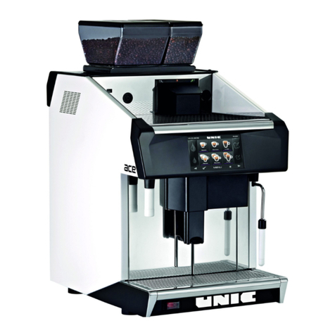
Unic Tango Ace Instruction Manual

1
ace
TECHNICAL NOTE
ace
Thank you for choosing UNIC, the rst French manufacturer
of professional espresso machines since 1919.
The manufacturer reserves the right to modify the
appliances presented in this publication without notice.
Read carefully the safety instructions before use.
TG9066 07/2019


3
ace
Contents
1-SAFETY INSTRUCTIONS...........................................................................................................5
2-STANDARD VERSIONS..............................................................................................................6
►TANGO ACE .........................................................................................................................................7
►TANGO ACE MT....................................................................................................................................7
►MODULE FRIGO ...................................................................................................................................8
3-MACHINE INSTALLATION .........................................................................................................9
►Preparation of the machine ................................................................................................................9
♦Unpacking the machine.......................................................................................................................................9
♦Installing the machine .........................................................................................................................................9
♦Fitting high feet....................................................................................................................................................9
►Hydraulic connections.........................................................................................................................9
►Electrical connections.......................................................................................................................10
►Connecting the ST module to the machine .....................................................................................12
♦LC hydraulic part...............................................................................................................................................12
►Installing the bins...............................................................................................................................12
4-COMMISSIONING......................................................................................................................13
►Switching on the machine and Turning on the heating..................................................................13
►Module ST...........................................................................................................................................13
5-INTERFACE................................................................................................................................15
►Main screen ........................................................................................................................................15
►Quick access screen / Code..............................................................................................................15
►Miscellaneous icons ..........................................................................................................................17
►Day/night programming.....................................................................................................................17
►Counters .............................................................................................................................................18
►Settings...............................................................................................................................................19
♦Other settings....................................................................................................................................................20
►Cleaning..............................................................................................................................................21
►Products..............................................................................................................................................22
►Maintenance .......................................................................................................................................23
►Access level........................................................................................................................................24
6-SETTINGS ..................................................................................................................................24
►Language ............................................................................................................................................24
♦Language selection...........................................................................................................................................24
►Personalization...................................................................................................................................24
♦Keyboard selection............................................................................................................................................24
♦Wallpaper..........................................................................................................................................................24
►CIM ...............................................................................................................................................25
►Backup ...............................................................................................................................................25
►Cleaning settings ...............................................................................................................................25
►Cleaning setup ...................................................................................................................................26
►Pre-infusion and STI .........................................................................................................................27
♦STI.....................................................................................................................................................................27
♦Tamping level ....................................................................................................................................................27

4
►Grinder calibration.............................................................................................................................27
►Computer connection........................................................................................................................28
►Connectivity........................................................................................................................................28
►Keyboard Menu creation ...................................................................................................................29
►Hot water & steam..............................................................................................................................29
► ‘PS’ Specic program ........................................................................................................................29
►‘PP’ Programmed parameters...........................................................................................................30
►Product management ........................................................................................................................30
♦Adding a drink...................................................................................................................................................30
7-CLEANING & MAINTENANCE.................................................................................................31
►Cleaning external outlets / housing .................................................................................................31
♦ Coee outlet......................................................................................................................................................31
♦Cappuccino outlet .............................................................................................................................................31
♦Steam wand......................................................................................................................................................31
♦Drip tray.............................................................................................................................................................31
♦Housing.............................................................................................................................................................31
►Cleaning Cycles .................................................................................................................................32
♦ Milk & coee cleaning .......................................................................................................................................32
♦ Coee cleaning .................................................................................................................................................32
♦Cappuccino cleaning (with LC) .........................................................................................................................33
♦Powder cleaning (ACE MT)...............................................................................................................................34
8-MAINTENANCE & TROUBLESHOOTING ..............................................................................35
►Description of cycles.........................................................................................................................35
♦1 group Cycles..................................................................................................................................................35
♦Cappuccino Cycle.............................................................................................................................................37
♦Hydraulic circuit ACE MT...................................................................................................................................38
►Component test..................................................................................................................................39
►Cooling machine ................................................................................................................................40
►History of errors.................................................................................................................................40
►Softener...............................................................................................................................................40
►Descaling ............................................................................................................................................40
►How to ugrade CPU and Display ......................................................................................................41
►Lists of cables ....................................................................................................................................44
♦Static relays.......................................................................................................................................................45
♦Connectors........................................................................................................................................................46
♦Fuses ................................................................................................................................................................48
►Electronic Cards ................................................................................................................................50
♦Turntable set .....................................................................................................................................................50
► LED Identication on card.................................................................................................................51
►Active components............................................................................................................................54
►List of error codes..............................................................................................................................56
►Electric wirings...................................................................................................................................58
♦Electric wirings 5/12V........................................................................................................................................60
♦Electric wiring 24V.............................................................................................................................................61
►Front panel replacement ...................................................................................................................62
5
ace
1-SAFETY INSTRUCTIONS
This device is intended to be used only for its specic use.
The manufacturer disclaims any liability for damage caused by abnormal use or abuse.
Children 8 years of age or older and persons with reduced physical, mental or sensory abilities, or lack of
experience and skill may use this device, if supervised by a qualied person, or they have received the
instructions for use and security necessary to understand the risks involved.
Supervise children to make sure they do not play with the appliance and they can’t make the cleaning &
maintenance of the machine.
Do not leave the packaging elements within reach of children. These elements are potentially a source of
danger.
The installation must be done by a qualied technician and following local and national regulations. He is
the only one to be authorized to access the internal parts of the device for maintenance and repair.
Useonlythetechnicalandsparepartsmanualsforproperfunctioningofthemachine,andavoidcompromising
safety.
Access to the service area is limited to persons with the necessary knowledge of safety and hygiene as well
as practical experience of the device.
Leaveenoughfreespacearoundthemachinetofacilitateitsuseandtopreformanymaintenanceoperations.
The device must not be:
- exposed to the elements of the external environment or placed in damp places,
- exposed to a water jet or splashing.
- installed in areas where the jets or high pressure cleaners are used.
The device must be:
- placed on a stable, level and horizontal surface
- used at an ambient temperature of 5°C to 35°C (41°F - 95°F), (if it is stored at an ambient temperature
below 5°C (41°F) the water circuit (boiler-piping) must be drained.)
- if the device freezes, wait 24 hours at a minimum temperature of 10°C (50°F) before restarting the device.
Before connecting the power and water supplies, check that the electrical and water network are in
accordance with the technical information plate of the device.
The power supply must be provided with the following safety features: power switch which completely
isolates the machine from the mains (gap between contacts of at least 3 mm), ecient earthing and an
eective circuit breaker for protection against earthing leaks; section of the conductors appropriate for a
power capacity.
Before connecting or disconnecting the power cable, switch the main switch onto position 0. If the power
supply cable is damaged, it must be replaced by the manufacturer, by its after-sales service technician or
similarly qualied persons, to avoid any danger.
For electrical safety, make sure that the device is properly earthed.
The manufacturer disclaims any liability for damage caused by improper earthing.
The device must be connected to a water network with a pressure of 1 to 8 bar (0.1 to 0.8 MPa) and a tap
readily accessible must be tted in front of the water supply tube. The device is to be installed with adequate
backow protection to comply with applicable federal state and local codes.
In case of emergency (re, surge, abnormal noise, etc. the rst thing to do is to cut o the current and close
the water tap.
Be careful not to obstruct the air inlets of the machine with towels or other objects.
Beware of hot surfaces such as cup heaters, the unit heads and the hot water and steam outputs.
Never install containers lled with liquid on the top of the machine.
Beware of jets of hot water or steam.
The machine should be descaled only by a qualied technician.

6
2-STANDARD VERSIONS
The ACE range is available in three colors, Brushed stainless steel, White or Black.
It is the sides and the rear shirt that change color.
DIMENSIONS
Width 45.3 cm
17.7”
Height 77 cm
30.3”
Depth 63 cm
24.8”
WEIGHT 100 kg
220 Lbs
CAPACITES
Steam / coee boiler 6.5 liters
- -
Coee grounds tray 100 coees
Numbers of cups / hour +200
STANDARD Power
Country Rep Voltage (V) Current Total Boiler
Philippines 0 415V tri + N 60Hz Ph 2+3: 7A
Ph 1+N: 21A 5550 W 4900 W
Europe 1 400V tri + N 50HZ Ph 2+3: 6.4A +6,4A
Ph 1+N: 10,5A 5200 W 4500 W
Europe 2 230V Mono 50Hz 25 A 5200 W 4500 W

UK 3 415V tri +N 50Hz Ph 2+3: 7,5A
Ph 1+N: 10,7A 5550 W 4900 W
UK 4 240V Mono 50Hz 25,7 A 5550 W 4900 W
Japon 5 200V tri +N 50Hz Ph 2+3: 6,2 A
Ph 1+N: 10 A 4060 W 3400 W
Japon 6 200V Mono 50Hz 22,5 A 4060 W 3400 W
Europe 7 230 tri 50Hz Ph 2+3: 6,4 A
Ph 1+N: 10,5 A 5200 W 4500 W
USA 8 240V Mono 60Hz 25,7 A 5500 W 4900 W
208V Mono 60Hz 23,2 A 4340 W 3680 W
USA 9 240V tri 60Hz Ph 2+3: 7,5 A
Ph 1: 10,7 A 5550 W 4900 W
208V tri 60Hz Ph 2+3: 6,5 A
Ph 1: 10,1 A 4340 W 3680 W
220V tri 60Hz 13.5 A 5150 W 4120 W

7
ace
►TANGO ACE
►TANGO ACE MT

8
►MODULE FRIGO
DIMENSIONS
Width 22.5 cm / 8.6”
Height 39.2 cm /15.4”
Depth 46.2 cm / 18”
Weight 14 kg / 30.8 Lbs
CAPACITIES
Milk tank (liter) 4

9
ace
3-MACHINE INSTALLATION
The machine must be installed on a horizontal plane.
A space of 5 cm (1.9”) should be left all around the machine; and do not obstruct the air inlets on the top of
the machine.
Provide an electricity supply corresponding to the power of the machine, a water supply and a “waste water”
drain.
►Preparation of the machine
The machine is delivered in a cardboard packing case and is screwed to a wooden pallet.
♦Unpacking the machine
- Cut the banding with shears.
- Open the packing case and remove the box containing the accessories.
- Unscrew the nuts holding the machine to the palette by tilting the pallet slightly.
- Separate the packing case from the pallet
- Remove the machine from the pallet and install it on wooden blocks.
- Remove the transport screws and washers.
♦Installing the machine
- Position the machine in its nal location, and level it using rubber washers if necessary.
♦Fitting high feet
Reference UNIC feet NSF: NM-176
Reference UNIC M8 x 16 bolts: 50402
For tting the aluminium feet, once the machine is installed in its location:
Screw the 50402 bolts to the aluminium feet, tip the machine onto the front
two feet to screw in the aluminium feet at the base of the rubber feet at the
back, and then do the same operation for bolting the feet to the front.
►Hydraulic connections
The machine is delivered with a complete connection kit including a stainless steel braided water hose 2 m
length and a drain hose 2m (78.7”) in length with a clamp located in the box of accessories.
- Slide the lower trims toward the front
- Remove the basin grille
- Remove the basin after unscrewing the central screw.
- Remove the right-hand side of the ACE,
- Screw the angled part (3/8’) of the stainless steel braided exible
pipe to the 3/8G tting of the water safety lter block and the straight
part (3/8’) on the water softener outlet union.
The water softener must be fed directly by the mains via a shut-o
tap allowing a sucient ow, Ø 8cm (3.1”) min.
Do not forget the seals. An opening in the chassis allows the hose
to pass through
- Put the softener in the ush position.
- Open the supply tap.
- Run a ush of the softener.
- Put the softener in the working position.
- Fit the drain hose on the tting located in the centre of the machine
- Check for leaks, and make sure that the drain tube allows a ow to
the main drain without any reverse slope.
- Ret the bowl, not forgetting the seal which must be between drain
blockandthebasin, and not between the central screwand the basin.
- Ret the trims and the basin grille.

10
►Electrical connections
Put the machine main switch in position 0, before any intervention.
The machine is delivered with a 5-core electric cable and a system of straps to allow for
3-phase or single-phase connection according to the installation.
The machine is pre-wired in accordance with the indications on the order and the country of destination.
Before connection, check the conformity of the machine with the electrical circuit to which it is going to be
connected.
To do this:
Compare the indications on the data plate, inside the drawer housing, with the characteristics of the circuit
to which the machine is to be connected. Remove the left side of the machine and check that the connection
of the straps on the terminal strip corresponds to the connection required (a diagram is glued to the inside of
the side).
ADAPTATION OF THE TOROIDAL TRANSFORMER TO THE VOLTAGE OF THE CIRCUIT
The machine is equipped with a multi-voltage transformer in order to ensure the correct supply voltage to the
electronics and 24-volt motors.
The machine is pre-set in the factory according to the country of destination (see page 6 and/or 7).
E.g.:
For Europe, the red wire is connected to the 230V terminal.
Oncetheconnectionhasbeenperformedcorrectly,itisnevertheless
advisable to check that the voltage is 230V± 5 %.
The low voltage should be about of 22V. These voltages should be
checked with the machine working and the main switch closed.
Réf: 46031
dessiné
Date controlé indice
Matière :
Débit :
Traitement :
Echelle :
Tolérances générales :
modification
+/- 0.1mm - angulaires: +/-0.3° - rugosité: Ra 6.3
NOTA:
LA PIECE DOIT ETRE CONFORME A LA DIRECTIVE EUROPEENNE 2008/35/CE RELATIVE A LA LIMITATION DE L'UTILISATION DE SUBSTANCES DANGEREUSES (CADMIUM,
PLOMB,CHROME HEXAVALENT,MERCURE, PBB OU PBDE)
AUTOCOLLANT BORNIER
TANGO SOLO ST
46031
0
0v/N 0v/N MV MR N/TR 200v 230v 240v
Connecter le fil ROUGE sur le plot indiquant la tension la
plus proche de la tension réelle mesurée sur votre réseau.
Connect the RED wire on the pin showing the voltage the
nearest of the actual voltage measured on your network.
NE JAMAIS DEPLACER LE FIL GRIS
NEVER MOVE THE GREY WIRE
Bleu
Blue
Bleu
Blue
Vert
Green
Rouge
Red
Bleu
Blue
ROUGE / RED
Etiquette adhésif fond blanc ecritures noires
Etiquette autocollante
impression Unic
08/12/2014 SC BG 0 CREATION

11
ace
T/Grd T/Grd
200.230.240 v
Mono+T/Gr
50/60HZ
T/Grd
5 FILS -5 WIRES 3 FILS -3 WIRES
T/Grd (Vert/Jaune )
(Green/Yellow) T/Grd
T/Grd
200 .220 .230v
3 Ph+T/Grd
50/60HZ
10/03/17 Ref=46240
T/Grd (Vert/Jaune )
(Green/Yellow)
T/Grd (Vert/Jaune )
(Green/Yellow)
BRANCHEMENT BORNIER / TERMINAL CONNECTING
(Gris / Grey)
(Noir / Black)
(Marron / Brown)
N (Bleu -Blue)
400. 415 v
3 Ph+N+T/Grd
50/60HZ
R
N
S
F
E
D
C
A
B
T
R
N
T
S
F
E
D
C
A
B
R
N
S
F
E
D
C
A
B
T
N
Ph1
(Gris / Grey)
(Noir / Black)
(Marron / Brown)
N (Bleu -Blue)
(Gris / Grey)
(Noir / Black)
(Marron / Brown)
T/Grd T/Grd
200.230.240 v
Mono+T/Gr
50/60HZ
T/Grd
5 FILS -5 WIRES 3 FILS -3 WIRES
T/Grd (Vert/Jaune )
(Green/Yellow) T/Grd
T/Grd
200 .220 .230v
3 Ph+T/Grd
50/60HZ
10/03/17 Ref=46240
T/Grd (Vert/Jaune )
(Green/Yellow)
T/Grd (Vert/Jaune )
(Green/Yellow)
BRANCHEMENT BORNIER / TERMINAL CONNECTING
(Gris / Grey)
(Noir / Black)
(Marron / Brown)
N (Bleu -Blue)
400. 415 v
3 Ph+N+T/Grd
50/60HZ
R
N
S
F
E
D
C
A
B
T
R
N
T
S
F
E
D
C
A
B
R
N
S
F
E
D
C
A
B
T
N
Ph1
(Gris / Grey)
(Noir / Black)
(Marron / Brown)
N (Bleu -Blue)
R
N
S
F
E
D
C
A
B
T
T
Sphase 1
phase 2
phase 3
(Gris / Grey)
(Noir / Black)
(Marron / Brown)
ST
ST
(Bleu -Blue)
R
N
S
F
E
D
C
A
B
T
T
Sphase 1
phase 2
phase 3
IN ALL CASES THE GREEN/YELLOW WIRE MUST BE CONNECTED TO THE EARTH OF THE
INSTALLATION

12
►Connecting the ST module to the machine
♦LC hydraulic part
With a cappuccino LC the refrigerator is delivered with the pipe already tted in the refrigerator, it remains
simply to feed it through the plate prepared for the purpose and x it to the cappuccino outlet end.
►Installing the bins
To avoid damage during transport, machines are
delivered with the bins removed
INSTALLING THE BINS:
- The bins are xed from behind. Respect the
direction of tting.
- Position the closing trap on the bins; pay attention
to the direction of the opening of the trap.
- Access to the trap is by removing the side.
- Capacity: 1.7 kg (4,5 liters) for the large bin.
- Capacity: 1.2 kg (3 liters) for the small bin.
INSTALLING POWDER BIN:
- Remove the powder cover forwards (locked by
the lock).
- The hoppers are xed from the rear. Observe the
mounting direction (picture).
- Reposition the cover and lock.
CAUTION:
Air must be able to circulate freely around the machine. The ventilation openings located at the rear of the
machine and on the top must not be obstructed.
The machine must not operate without its legs.

13
ace
4-COMMISSIONING
►Switching on the machine and Turning on the heating
Once all the connections are made and checked (water supply, electricity supply and drain).
Set the main switch in position 1.
As soon as the electricity is switched on, the boilers ll automatically.
Remember to open the water tap supplying the machine.
The heating of all the parts starts automatically if the lling is correct.*
When the machine reaches its operating temperature, it performs a self-check.
Theseinitializationphasesare very important for the proper functioningof the machine.Theyareonlypossible
if the coee grounds drawer is in place, and they must not be interrupted, for instance by removing the drawer.
(The steam pressure and the temperature of the groups are visible on the screen during heating).
The machine is operational once heating has been switched on and the self-check performed.
It is advisable to leave the machine heating on permanently.
►Module ST
The temperature display indicates the ambient temperature of the refrigerator.
Specicities:
Compressor electrical regulation
Contact temperature of the liquid
Liquid level probe (triggered at <1.2 liter)
9 liter container capacity
Dimensions:
Outer (width * Length * height) 8.6” x 18” x 15.4”
Key locking of the
refrigerator
Temperature display
UNIC part number for the display: 45039

14
1. Compressor indicator
2. Fan
3. Defrosting
4. Auxiliary output (AUX)
5. Clock (RTC)
6. Alarm
7. Numbers
1. Press 3s, to switch ON/OFF
2. Press <1s : cancel sound alarm
Press =1s : temperature setting
Press 3s : access programming parameters
3. Press 1s : Turn ON/OFF heats cups
Parameter navigation
The operating parameters, modiable through the front keypad, the access is protected by a password (default
= 22) which prevents accidental changes by unauthorized persons.
Access to parameters:
• press the SET key for 3s (in case of alarm, cancel the buzzer). On the screen appears the code of the
parameter ‘PS’ (password),
• conrm by pressing the SET key, to enter the password, scroll with UP and DOWN (default = 22), then
conrm with SET,
• use the UP and DOWN keys to scroll through the parameters.
• press SET to display the value associated with the parameter;
• increase or decrease the value with the UP and DOWN keys respectively;
• press SET to temporarily save the new value and return to the parameter display;
• repeat the procedure for the other parameters that you wish to modify;
• press the SET key for 3s to permanently save the parameters and exit the modication procedure.
Main parameters:
/5 = selection °C/°F
Temperature setting
from 38.3°F to 46.4°F
Normal use
warming cups ON
/C1 = offset temp. probe H4 = Disabling the buzzer
Temperature
Cup warmer indication ON/OFF
Main alarmA5 = Indication empty
container and / or missing container
• Press during 1s on SET, after a few moments,
the programmed value ashes;
• Increase or decrease the value with UP or
DOWN;
• Press on SET to conrm the new value
A4 = Disabling
presence sensor
Explicative note of display 45039 (TG9191)

15
ace
5-INTERFACE
The level 0 (User) includes the main screen for making the products, the hot water, the steam and access to
the quick access screen, which allows the user to have direct controls such as to Stop the machine or put it
in Standby.
►Main screen
Previous page Next page
Manual trap Favourites
Erreur code info
Type of productType of grinder
Large dose of hot water
Small dose of hot water
Large dose of steam
Small dose of steam
►Quick access screen / Code
Information relating to the
whole of the machine in
real time
Quick access
to the menu
“Cleaning”
Return to the
main screen
Key to stop the machine
Access to
levels 1 & 2 by
password
Key for putting the
machine in Standby

16
Maintenance p.23
Day/Night programming p.17
Counters p.18
Main menu
Products p.22
Cleaning p.21
Other settings p.20
Settings p.19
Once the security code has been conrmed the levels 1 (Customer) or 2 (technician) are accessible (according
to the Code).

17
ace
►Miscellaneous icons
Scrolls the drinks keyboards.
Icon to access the «Quick access / code» screen
Return to the main screen
Return to the previous page
Key to activate the opening of the cover of the manual trap for 10 seconds; the time required
to introduce 1 or 2 doses of ground coee and close the trap again.
Access to favourite products on the main screen
Icon for copying a le and/or data
Icon for indicating settings (e.g.: settings of a product)
Icon for saving data and/or parameters
Icon for conrming data and/or parameters
Icon for cancelling data and/or parameters
Icon for indicating the remaining time of the compulsory cleaning of the machine (before
blocking).
Icon for accessing error codes / alarms activated.
►Day/night programming
Allows you to schedule the days and times of
automatic switching to night mode (machine in
standby, reduced heating temperatures), and day
mode; may or may not be followed by an automatic
cleaning cycle.
To add a time slot:
- Press «Add a time slot»
- Schedule the desired times
- Remember to conrm
- you can then either copy this same time slot
for the next day, or add a new one.
If you want to re-schedule your time slots, press the button at the bottom right of the screen for 3s.
Remember to save your settings.
Note: When Standby is enabled the regulation of the group and the coee boiler goes to 70°C and 0.1 bar
for the steam boiler
All screens are o
All safety functions remain activated
Standby output: resumption of the normal regulation is done 10 minutes before the exit from standby.

18
►Counters
This menu allows you to view the statistics for all the products produced on the machine.
Note: At level 2, it is possible to perform a general reset of all counters.
Level 2 (technician) required

19
ace
►Settings
This menu allows you to adjust the settings of the machine such as the date and time, the desired language,
the boiler temperatures and the LED colour and brightness.
Note: Some settings are only accessible or changeable at level 2 (technician).
Modiable at level 2 (technician) p:24
Level 2 (technician) required p:25
Language p.24
Customizing p.24

20
♦Other settings
Pre-infusion & STI p.27
Grinder calibration p.27
Cleaning settings p.25
Computer connection p.28
Cleaning setup p.26 Connectivity p.28
Other manuals for Tango Ace
1
Table of contents
Other Unic Coffee Maker manuals

Unic
Unic AURA 2 User manual

Unic
Unic DIVA User manual

Unic
Unic AURA 2GR Instruction Manual

Unic
Unic Tango STP Configuration guide

Unic
Unic Phoenix-R User manual

Unic
Unic Pony 4 User manual

Unic
Unic Stella Epic Specification sheet

Unic
Unic STELLA EPIC 3 User manual

Unic
Unic Stella di Caffe User manual

Unic
Unic Stella Epic User manual

Unic
Unic Tango Ace Service manual

Unic
Unic Tango ST Duo Instruction Manual

Unic
Unic Mira Instruction Manual

Unic
Unic Mira User manual

Unic
Unic STELLA User manual

Unic
Unic Stella di Caffe Manual

Unic
Unic Rumba Operation and maintenance manual

Unic
Unic Stella di Caffe User manual

Unic
Unic Tnira classic Configuration guide

Unic
Unic Tango Instruction Manual