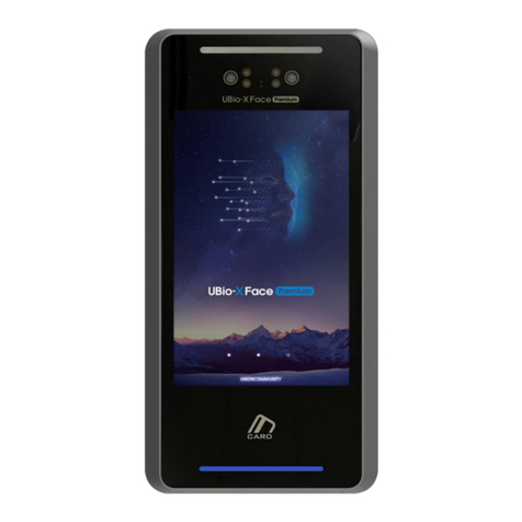
UNIONCOMMUNITY UBio-X Face Premium User manual

UBio-X Face Premium
Installation Guide
Doc Eng Ver1.0
Jul.,05.2022
R&D Center
Union Community Co., Ltd

Contents
Product Introduction
Front Part Name & Functions
Rear Part Name & Functions
Dimensions
Product Specifications
Cable Specifications
Components
Check in advance
Safety Precautions
Correct Face Enrollment and Authentication Method
Correct Fingerprint Enrollment and Authentication Method
Installation
Notes on Installation
Installation Location
Fixing the Bracket
Wiring Connection
Wiegand Connection
Ethernet Connection
Lock Connection
Fail Safe Lock / Exit Button / Door Sensor
Fail Secure Lock / Exit Button / Door Sensor
Automatic Door / Exit Button
Motor Lock / Exit Button
Warning Lamp Connection
Lock Controller connection via RS-485
Input Power Connection
External Relay connection
FCC Compliance Information
EU Declaration of Conformity (CE)
2

Front Part Name & Functions
illuminance Sensor
Product Introduction
Name Function Descriptions
Flash LED Turn on the LED Light for Face Authentication in a dark
environment.
Illuminance Sensor Measure the illuminance around the Product.
IR LED Turn on the IR light for Face Authentication.
IR Camera Capture the IR images.
Camera Capture the Color images.
Microphone Enter the user’s voice when connecting to VoIP
Touch LCD Display Provides a UI for operation.
RF Card & Mobile Card
recognizes Area The part that recognizes the RF Card or Mobile Card.
Speaker Output the Guide message and voice when VoIP is
connected.
USB Memory Slot Connect the USB Memory.
Fingerprint Sensor Input the Fingerprint.
Barcode Reader Scan the Barcode Image
IR LED
IR Camera
Microphone
Camera
Flash LED
Touch LCD Display
RF Card & Mobile Card
recognizes Area
Speaker
Barcode Reader
USB Memory Slot
Fingerprint Sensor
3

Name Function Descriptions
State Input(5pin) Connect Inside Open/ Door Lock State Input Cable
Wiegand
In/Out(5pin) Connect the Wiegand Input / Output Cable
RS-232(3pin) Reserved for R&D only
Lock Output(7pin) Connect the Lock Cable
Motor Lock(2pin) Connect the Motor Lock Cable
RS-232(3(5)pin) Connector the RS-232 Cable for Barcode Reader or Receipt
Printer for Meal
5V Output(2pin) Connect the 5V power output for peripheral devices
FUSE Main Power FUSE
RS-485 Termination
Resistor Set SW Set the RS-485 Termination Resistor
Ethernet Connect the Ethernet Cable
Input Power/RS-
485(4pin) Connect the 15/24V Power Adapter & RS-485 Cable
Lock Power Set SW Set whether to supply power to the Lock
Warning Lamp(3pin) Connect the Warning Light Cable
Thermal Image
Camera(5pin) Connect the Thermal Image Camera Interface Cable
Fingerprint
Sensor(5pin) Connect the Fingerprint Sensor Interface Cable
Input Power/RS-485(4pin)
Lock Power Set SW
FUSE
RS-485 Termination
Resistor Set SW
Lock Output(7pin)
RS-232(3pin)
Warning Lamp(3pin)
Ethernet
Thermal Image
Camera(5pin)
Wiegand(5pin)
State Input(5pin)
Motor Lock(2pin)
RS-232(3(5)pin)
5V Output(2pin)
Fingerprint Sensor(5pin)
4
Rear Part Name & Functions

Dimensions
UBio-X Face Premium
UBio-X Face Premium FQR
143.3
289.5
23.8
343.2
143.3
73.6
5

Product Specifications
Classification Feature Specifications
System
CPU 1.8GHz Quad Core
Memory 16GByte eMMC + 4GByte DDR
LCD 8inch TFT IPS Panel, 800x1280 pixel
Touch Screen Capacitive Touch
Authentication
Method
Biometric Face & Fingerprint Authentication
RF Card
ISO14443 Type A/B, Felica, ISO15693, HID15693,
MiFare, 125KHz EM, HID Prox,
HID ISO14443 MiFare/SEOS/DesFire(Optional)
HID ISO15693 SE(Optional)
RF Card Reading Range 50mm
Mobile Card Reading
Range 10cm
Password Support
Capacity
Max User 500,000
Max 1:N User Face : 30,000
Fingerprint : 50,000
Max 1:1 User
Face : 100,000
Fingerprint : 100,000
Card : 500,000
Max Log 10,000,000 Log
Max Image Log 20,000 Log
Communication
Ethernet TCP/IP 10/100/1000Mbps Auto MDI/MDI-X
USB
USB2.0 Host 1 port : Fingerprint Sensor connection
USB2.0 Host 1port : Thermal image Camera
USB3.0 C-type OTG 1port : External FW Download
RS-485 1port External Lock Controller connection
RS-232 1port Barcode Reader connection
Wi-Fi IEEE802.11 b/g/n
Wiegand IN/Out ea1port
VoIP Support
I/O
Relay Output 2 Relay Support
State Input 4 port Support, Tamper Support
Available Lock EM Lock, Strike Lock, Dead-bolt Lock, Motor Lock,
Automatic Door
Power
Power 15VDC 4A or 24VDC 2.5A
Current Consumption Max 1.5A@15VDC
Environment
Water Proof IP55 (Optional IP65)
Operation/Storage Temp. -20 ~ 60℃/ -40 ~ 70℃
6
15V/24V Power Connection
PIN Function/Label Color
1 5V Output/5V SKY BLUE
2 Ground/GND BLACK
5V Output Power Connection
Motor Connection PIN Function/Label Color
1 Motor+ /M+ YELLOW
2 Motor- /M- BROWN
RS-232 peripheral Device Connection
Warning Lamp Connection PIN Function/Label Color
1 Green Lamp/L_G GREEN
2 Red Lamp/L_R RED
3 Ground/GND BLACK
PIN Function/Label Color
1 nc
2 RS232 TXD/R2T RED
3 RS232 RXD/R2R BROWN
4 Ground/GND BLACK
5 nc
PIN Function/Label Color
1 Input Power/ 15V/24V RED
2 Ground/GND BLACK
3 nc
Cable Specifications
7

PIN Function/Label Color
1 Lock1 NC/L1NC BROWN
2 Lock1 Com/L1C GRAY
3 Lock1 NO/L1NO WHITE
4 Lock2 NC/L2NC BROWN
5 Lock2 Com/L2C GRAY
6 Lock2 NO/L2NO WHITE
7 Ground/GND BLACK
PIN Function/Label Color
1 Wiegand Out 0/WO0 ORANGE
2 Wiegand Out 1/WO1 YELLOW
3 Wiegand In 0/WI0 BROWN
4 Wiegand In 1/WI1 PINK
5 Ground/GND BLACK
Wiegand IN/OUT Connection
State Input Connection
PIN Function/Label Color
1 Door Monitor 0/DM0 YELLOW
2 Door Monitor 1/DM1 GREEN
3 Door Monitor 2/DM2 BLUE
4 Inside Open/EXT ORANGE
5 Ground/GND BLACK
Lock Connection
8

Components
UBio-X Face Premium
9
* The Power Input Cable is connected to the product.

UBio-X Face Premium FQR
10
* The Power Input Cable is connected to the product.
* The Metal Bracket & Plastic auxiliary bracket are fastened to the product.

UBio-X FQR
11
* A separate product configuration to add FQR functionality to the UBio-X Face Premium.

Safety Precautions
WARNING : Failure to follow the instructions may result in death or
serious injury to the user.
CAUTION : Failure to follow the instructions may result in moderate
injury or property damage.
WARNING
Installation
Do not disassemble, repair or modify arbitrarily.
* This may result in electric shock, fire or product damage.
* Damages caused by user’s any modifications or repair can void manufacturer’s
warranty.
Do not install in a humid place.
* This may result in electric shock & product damage.
Operation
Do not place electric heaters near the product.
* This may result in fire or product damage.
Do not operate the product with wet hands or allow liquids such as water
to enter the product.
* This may result in electric shock, fire & product damage.
Do not spray directly with water or clean with benzene, thinner or alcohol.
* This may result in electric shock, fire & product damage.
Do not spray insecticides or flammable sprays on the product.
* Not only is it harmful to the human body, but it may also cause product damage,
electric shock or fire.
CAUTION
Installation
Do not install in a place exposed to direct sunlight.
* This may result in malfunction, deformation or discoloration.
Do not install in dusty places.
* This may result in malfunction.
Do not install in a place with severe temperature change.
* This may result in malfunction.
Operation
Do not bring magnets close to the product.
* This may result in a risk of malfunction.
Avoid impact the product or scratching it with sharp objects.
* This may result in damage or cause malfunction.
Check in advance
12

Correct Face Enrollment and Authentication method
Face Enrollment Method
* Do not wear a hat or sunglasses that cover your face.
* Register after making sure that the lower part of the forehead is
not covered by hair, etc. (Criteria for taking passport photos)
* Keep the distance between the product and your face about 50cm.
(Position the face within the guide line on the LCD screen.)
* Follow the instructions to register your face poses.
* When wearing glasses, it is recommended to register both before
and after wearing glasses.
Face Authentication Method
* Just look at the camera from the front.
Notes
* It is best to register at the place where the product is installed.
* Taking a pose different from the registered face may decrease the
face recognition rate.
It is recommended to face forward as much as possible.
* If you change the glasses you are wearing, authentication may fail,
so please wear the new glasses and register your face again.
* Thick frames or sunglasses can reduce the face recognition rate.
* If your face is obscured including your eyebrows, it can reduce
your face recognition rate.
13

Correct Fingerprint Enrollment and Authentication
Method
Correct Fingerprint Enrolment Method
* If possible, use your index finger to input as if you were handprinting.
Typing with only your fingertips touching is not the right way to type.
Make sure that the very center of the fingerprint touches the center of
fingerprint sensor glass.
* If possible, enter the fingerprint of your index finger.
By using your index finger, you can input fingerprints accurately and
reliably.
* Check for indistinct fingerprints or abrasion.
Fingerprints that are too dry or wet, blurry or scratched fingerprints
are difficult to recognize. In this case, register the fingerprint of
another finger.
Notes according to user fingerprint state
Depending on the user’s fingerprint state, it may not be possible to
use the fingerprint or there may be difficulties in using it.
* If the fingerprint is weak or the fingerprint is damaged and cannot be
used, you will need to use your face, card or password.
* If your hands are dry, you can use it by blowing your breath.
* For children, if the size of the fingerprint is too small or indistinct, it
may be difficult or impossible to use, and it is necessary to register
the fingerprint again every 6 months.
* In case of the elderly, registration may not be possible if there are
calluses or severe scratches on the fingerprint to be registered.
* It is recommended to register two or more user’s fingerprints if
possible.
14

Installation
300mm
** Side by side installation ** Wall front/Back installation
300mm Wall
Precautions on Installation
* Be sure to install the product indoors.
* Do not install in an environment with backlight or direct sunlight as this
may reduce the face recognition rate.
* When using a mobile card, keep a distance of at least 1m to avoid
signal interference.
* To avoid RF signal interference, keep the distance between products as
shown in the figure below.
15
Installation Location
* Select a location to mount the product as shown in the figure below.

Fixing the Bracket
* Fix the bracket firmly in the selected position using the bracket fixing
screws.
Fix using metal bracket & auxiliary bracket
Fix using metal bracket
* Fasten the metal bracket with 4x25(4ea) wall mounting screws.
* Fasten the plastic auxiliary bracket with 4x25(4ea) wall mounting screws.
* Fasten the metal bracket to the auxiliary bracket using 4x8(6ea) bracket
mounting screws.
16

Wiring Connection
Wiegand Connection
Wiegand Input Connection
Wiegand Output Connection
RF Card Reader
VS-R20D
UBio-X Face Premium
3/WI0
4/WI1
5/GND
Controller
1/WO0
2/WO1
5/GND
17

Ethernet Connection
Ethernet Hub Connection
* Connect to PC through Ethernet HUB using CAT-5 UTP cable.
Direct connect to PC
* With Auto-MDI/MDI-X function, it is directly connected to PC using
Cross cable or straight type CAT-5 UTP cable.
PC
Ethernet HUB
UBio-X Face Premium
PC
UBio-X Face Premium
18

Lock Connection
Fail Safe Lock
* Fail Safe Lock opens when the power of the product is cut off due to a power failure, etc.
* When the lock is locked, power is supplied to the lock, and when the power supplied to the
lock is cut off by the door opening control operation, the door is opened.
* The basic connection method is the same for the Deadbolt Lock, Strike Lock, EM Lock.
* If 24V lock is required while supplying power for lock operation from the product, change the
product’s power supply to a 24V adapter.
* Apply power after completing all wiring.
* In order to protect the product from the counter electromotive force generated during lock
operation, connect the diode at a location close to the lock as shown in the figure with the
correct polarity.
One system, one Lock connection/ Door state input & Exit button
* SW4 On position
EB-030
Exit button
Lock
4/EXIT
1/L1NC
7/GND
1/DM0
5/GND
(+)
(-)
UBio-X Face Premium
Two system, one Lock Connection/ Door state input
* SW4 On position
* SW4 Off position
System 1
System 2
Lock
4/EXIT
1 L1NC
7/GND
1/DM0
5/GND
2/L1C
3/L1NO
(+)
(-)
One system, two Lock connection/ Door state input & Exit button
* SW4 Off position
EB-030
Exit button
Lock 1
4/EXIT
1/L1NC
7/GND
1/DM0
5/GND
12V or 24V
Adapter
2/ L1C
(-)
(+)
(+)
Lock 2
(-)
19

Fail Secure Lock
* The Fail Secure Lock close when the product power is cut off due to power failure, etc.
* When the lock is closed, power is not supplied to the lock and the door opens when
power is supplied to the lock by the door open control operation.
* You must use fail secure lock as the lock type.
* In order to protect the product from the counter electromotive force generated during lock
operation, connect the diode at a location close to the lock as shown in the figure with the
correct polarity.
One system, one Lock connection/ Door state input & Exit button
* SW4 On Position
EB-030
Exit button Lock
4/EXIT
3/L1NO
7/GND
1/DM0
5/GND
(+)
(-)
UBio-X Face Premium
Two system, one Lock connection/ Door state input
* SW4 On Position
Lock
4/EXIT
3/L1NO
7/GND
1/DM0
5/GND
* SW4 Off Position
2/L1C
3/L1NO
System 1
System 2
(+)
(-)
20
Other manuals for UBio-X Face Premium
1
Table of contents
Other UNIONCOMMUNITY Touch Terminal manuals

UNIONCOMMUNITY
UNIONCOMMUNITY AC-5000 User manual

UNIONCOMMUNITY
UNIONCOMMUNITY MiKey AC1100 User manual

UNIONCOMMUNITY
UNIONCOMMUNITY UBio-X Face Premium User manual

UNIONCOMMUNITY
UNIONCOMMUNITY AC-6000 User manual

UNIONCOMMUNITY
UNIONCOMMUNITY AC-5000RF User manual

UNIONCOMMUNITY
UNIONCOMMUNITY VS-R20DSC User manual
Popular Touch Terminal manuals by other brands

Elo TouchSystems
Elo TouchSystems 15A2 for wireless card Quick installation guide for modem card

POSIFLEX
POSIFLEX HS-2510W-2D user manual

Omron
Omron NT31 Series Operation manuals

Grundfos
Grundfos MGE 71 instructions

Welch Allyn
Welch Allyn Transaction Team 1500 Startup guide

Axon
Axon POS3600 Series user manual