manuals.online logo
Brands
  1. Home
  2. •
  3. Brands
  4. •
  5. UnionSpecial
  6. •
  7. Sewing Machine
  8. •
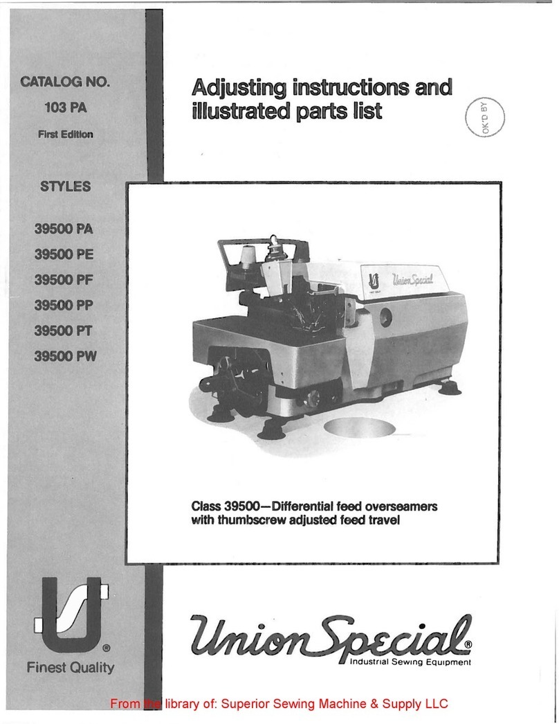
  9. UnionSpecial 39500N Series Instruction sheet

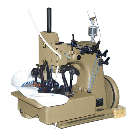
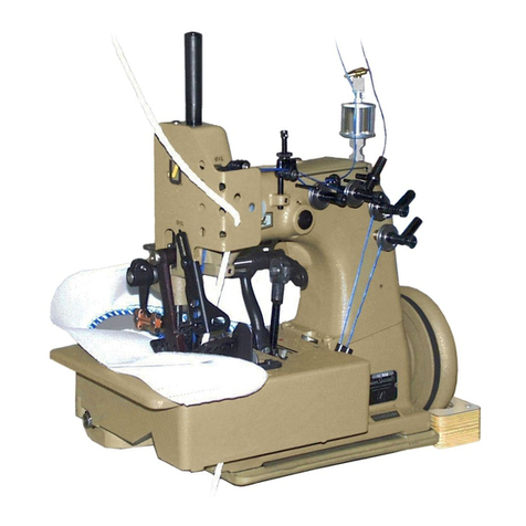
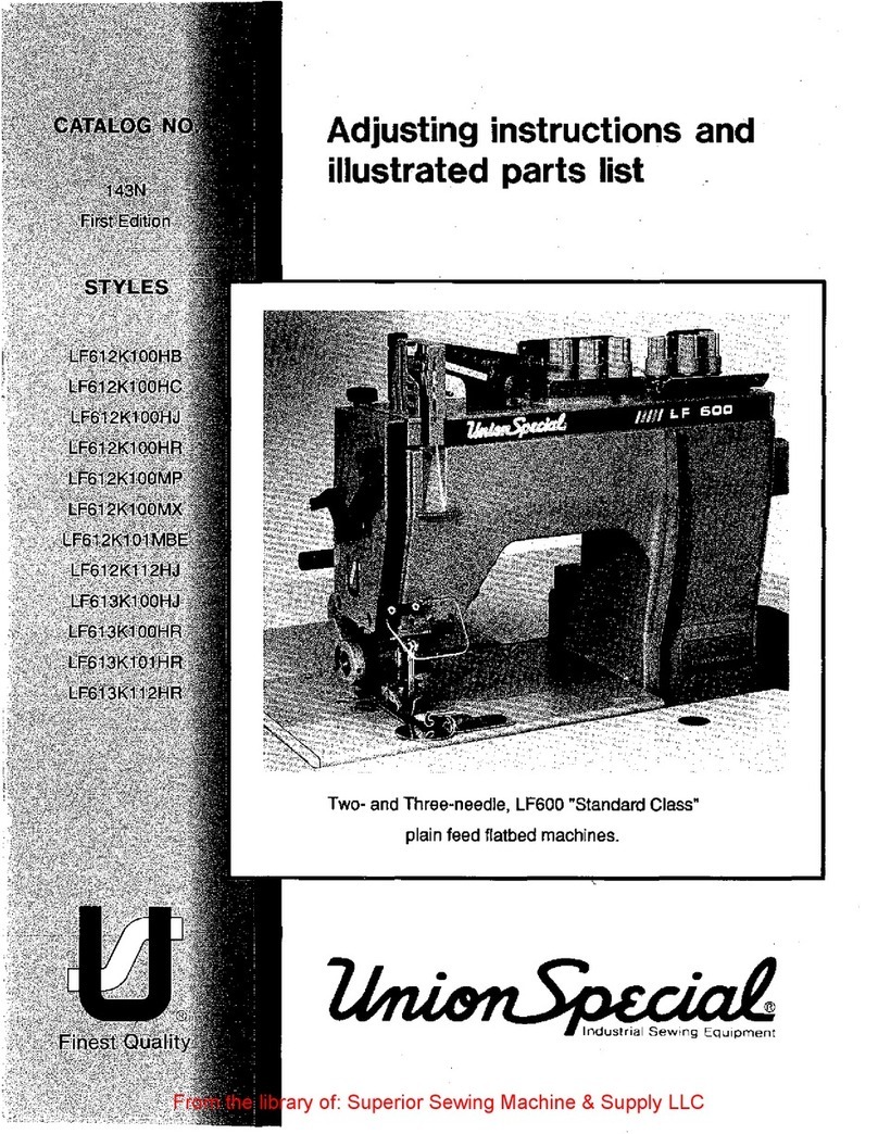
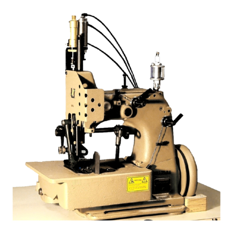
UnionSpecial 39500N Series Instruction sheet

FINEST
QUALITY
STYLES
39500N
CATALOG
No.
103R
SECOND
EDITION
LEWIS
•
COLUMBIA
CLASS
39500
.
S
TREAMLINED
®
INDUSTRIAL
S E
WING
MACHINES
HIGH
SPEED
OVERSEAMERS
CH
I
CAGO
From the library of: Superior Sewing Machine & Supply LLC
---------------------------------------------------------------------
From the library of: Superior Sewing Machine & Supply LLC
Fe
br
~
a
ry.
1971
Catalog
No.
103
R
INSTRUCTIONS
FOR
ADJUSTING
AND
OPERATING
LIST
OF
PARTS
CLASS
39500
Style
39500
N
Second
E
clition
Copyright
1957
by
Union
Special
Machin
e
Co.
Rights
Reserved
in
All
Countries
MACHINE COMPANY
INDUSTRIAL
SEWING
MACHINES
CHICAGO
Printed
in
U.S.A.
3
From the library of: Superior Sewing Machine & Supply LLC
FOREWORD
The
Class
39500
machine
is
Union
Special'
s·
latest
overedger.
New
streamlined
styling,
automatic
lubrication,
and
light
running
high
speed
performance
are
characteristics
of
these
machines.
All
parts
are
made
by
precision
methods
insuring
complete
interchangeability.
It
is
our
constant
aim
to
furnish
carefully
prepared
information
that
will
enable
the
customer
to
secure
all
possible
advantages
from
the
use
of
Union
Specials.
The
following
pages
contain
valuable
operating
and
adjusting
data,
and
illustrates
and
describe
the
parts
for
Styles
in
Class
39500.
Union
Special
representatives
will
be
found
in
all
manufacturing
centers,
anxious
to
cooperate
with
you
to
plan
and
estimate
requirements.
~
MACH/NECOMPANY
Engineering
Department
4
From the library of: Superior Sewing Machine & Supply LLC
IDENTIFICATION
OF
MACHINE
Each
Union
Sp
e
cial
carries
a
Style
number
which
is
stamped
in
the
name
plate
on
the
machine.
Style
numbers
are
classified
as
standard
and
special.
Standard
Style
numbers
have
one
or
more
letters
suffixed,
but
never
contain
the
letter
"Z".
Example:
"Style
39500
N".
Special
Style
numbers
contain
the
letter
"Z".
When
only
minor
changes
are
made
in
a
standard
machine,
a
"Z"
is
suffixed
to
the
standard
Style
number.
Example:
"Style
39500
NZ".
Styles
of
machines
similar
in
construction
are
grouped
under
a
Class
num-
ber,
which
contains
no
letters.
Example:
"Class
39500".
APPLICATION
OF
CATALOG
This
catalog
applies
specifically
to
the
standard
Styles
of
machines
as
listed
herein.
It
can
also
be
applied
with
discretion
to
some
special
machines
in
Class
39500.
All
references
to
directions,
such
as
right
and
left,
front
and
back,
etc
.•
are
taken
from
the
operator's
position
while
seated
at
the
machine.
Operating
direction
of
handwheel
is
away
from
operator.
STYLES
OF
MACHINES
Single
Curved
Blade
Needle,
Two
Looper,
Three
Thread,
Overseaming
Ma-
chine.
Plain
Feed,
Trimming
Mechanism
with
Spring
Pressed
Lower
Knife,
Automatic
Lubricating
System.
39500
N
For
seaming
garment
pockets
and
similar
operations
on
heavyweig-ht
fabrics.
Seam
specification
504
SSa-1,
standard
seam
width
3/16
to
7/32
inch;
stitch
range
8-20
per
inch
1
standard
setting
12
per
inch;
cam
adjusted
plain
feed.
OILING
CAUTION!
Oil
was
drained
from
machine
when
shipped,
so
reservoir
must
be
filled
before
beginning
to
operate.
Oil
capacity
of
Class
39500
is
six
oun8es.
A
straight
mineral
oil
of
a
Saybolt
viscosity
of
90
to
125
seconds
at
100
Fahrenheit
should
be
used.
Machine
is
filled
with
oil
at
spring
cap
in
top
cover.
Oil
level
is
checked
at
sight
gauge
on
front
of
machine.
Red
tip
of
oil
indicator
should
show
between
gauge
lines
when
machine
is
stationary.
Machine
is
automatically
lubricated.
No
oiling
is
necessary,
other
than
keeping
main
reservoir
filled.
Check
oil
daily
before
the
morning
start;
add
oil
as
required.
Drain
plug
screw
is
located
at
back
of
machine
near
bottom
edge
of
base.
It
is
a
magnetic
screw
designed
to
accumulate
possible
foreign
materials
which
may
have
entered
the
crank
case.
It
should
be
removed
and
cleaned
periodi-
cally.
NEEDLES
Each
UnionSpecialneedle
has
both
type
and
size
number.
The
type
number
denotes
the
kind
of
shank,
point,
length,
groove,
finish
and
other
details.
Th
e
size
number,
stamped
on
the
needle
shank,
denotes
largest
diameter
of
blade,
measured
in
thousandths
of
an
inch,
midway
between
shank
and
eye.
Collec-
tively,
type
and
size
number
represent
the
complete
symbol
which
is
given
on
the
label
of
all
needles
packaged
and
sold
by
Union
Special.
5
From the library of: Superior Sewing Machine & Supply LLC
NEEDLES
(Continued)
Style
39500
N
uses
a
curved
blade
needle.
The
standard
needle
for
this
style
is
Type
154GAS.
It
is
a
curved
blade,
standard
length,
single
groove,
shallow
spot,
long
tapered
point,
struck
groove,
chromium
plated
in
sizes
022,
025,
027'
029, 032, 036, 040,
044,
049,
054
..
To
have
needle
orders
promptly
and
accurately
filled,
an
empty
package,
a
sample
needle,
or
the
type
and
size
number
should
be
forwarded.
Use
de-
scription
on
label.
A
complete
order
would
read:
"1
000
Needles,
Type
154GAS,
Size
036".
Selection
of
proper
needle
size
is
determined
by
size
of
thread
used.
Thread
should
pass
freely
through
needle
eye
in
order
to
produce
a
good
stitch
forma-
tion.
Success
in
the
operation
of
Union
Special
machines
can
be
secured
only
by
use
of
needles
packaged
under
our
brand
name,
~,
which
is
backed
by
a
reputation
for
producing
hi
0
hest
quality
needles
in
materials
and
workmanship
for
more
than
three-quarters
of
a
century.
CHANGING
NEEDLES
Release
pressure
on
presser
foot
by
turning
presser
foot
release
bushin
g
(U,
Fig.
1)
and
swing
presser
arm
(H)
out
of
position.
Turn
handwheel
in
oper-
ating
direction
until
needle
is
at
its
lowest
point
of
travel.
Usin
g he
xa
g
onal
socket
wrench
No.
21388
AU
furnished
with
machine,
loos
en
ne
e
dle
clamp
nut
about
1
/4
turn.
Again
turn
handwheel
until
needle
is
at
hi
gh
pos
i
tion;
wi
th-
draw
needle.
To
replace
needle,
leave
needle
holder
at
high
posit
i
on
and,
wi
th
the
flat
to
the
left,
insert
needle
in
holder
until
it
rests
aga
in
st
stop
pin.
K
ee
pin
g
needle
in
this
position,
turn
handwheel
until
holder
is again
at
its
low
po
int
of
travel;
then
tighten
nut.
Return
press
er
arm
(H)
to
positio
n; r e
-lock
pr
es s
er
foot
release
bushing
(U).
THREAD
STAND
Afterthread
comes
from
cone
on
thread
stand
(V,
Fig.
1), it i s
brou
g
ht
up
through
back
thread
eyelet,
th
en
down
throu
gh
fro
nt
thr
e
ad
eyel
et
(W).
Nex
t
it
is
threaded
through
each
pair
of
hole
s
in
tens
ion
thread
g
uid
e wir e (A).
down
right
hand
hole
and
up
throu
gh l e
ft
hand
hol
e .
Then
thread
cont
i
nu
es
be
tw
ee
n
tension
discs
(AD),
throu
gh
slot
(AE),
and on
throu
gh
th
rea
d guide (B
).
THREADIN
G
Only
parts
involv
ed in
thr
e
adin
g
are
s
hown
in
threadin
g diagr am (
Fig
. 1
).
Parts
are
plac
ed
in
th
eir
relative
posit
i
ons
for
clar
it
y.
It
will
simplify
thr
e
adin
g
this
m a
ch
ine
to
f
oll
ow
r e
comm
e
nd
ed
se
qu
ence
of
threadin
g
low
er
looper
first,
upper
loo
pe
r
se
cond,
and
n
ee
dl
e
th
ir
d.
Before
b
egi
nning
to
thr
e
ad,
swin
g
clo
th
plate
open,
tu
r n h
andwh
ee
l in
op
er
-
atin
g
direct
i
on
until
ne
e
dle
(N)
is
at
hi
gh
position,
r
ele
a
se
pr
ess
ur
e
on
pr
esse
r
foot
by
turn
ing
presser
foot
r e
lease
bu
s hing (U);
and
s
wi
ng
pr
esser
a
rm
(H)
out
of
position.
Be
sure
thr
e
ads,
as
th
ey
com
e
from
t
he
ten
si
on
thr
ea
d guide,
are
b
et
w
ee
n
tens
ion
d
is
cs (AD)
and
in diagon
al
slot
s
(A
E ) in ten
si
on po
st
s
(AC).
(j
From the library of: Superior Sewing Machine & Supply LLC
.,.,.,
, '
llilitll
Cll
S I 011 1
ut
I'J:IIren
~
ion
Po
s t
BJT,
· ns
aon
l' o
.<
t
;';
lot
Ten:<ion
Thread
1!1
Thread
Guioc
BUpper Looper
Thread
Ey
e!
et
~Auxiliary
Looper
Thread
Ey
ele
IJ
Lower
Loo
p
er
Thr ad E
yel
et
IJ
Fabric
Guard
Br
ac
ket
aF'rame LoopPr
CJrr,.~
~
•
·r
Arm
Fig.
1
7
Cone Suppo!'l
Pres.rr
foot
HP!
en•e
H
u
s
hin
~
----------------
---
--
---
---
-
--
--
----
..
---
' ·
---
--- '
Thread
P
ull-o
ff
-·<-
..
~
'
',
"t--
-
--
-
----
NPPdle
Th
read C
am
!
~11-off
.....
__
.:.,.
.,
...
--
-
--
-
---
Nee
dle
Thr
e
ad
E
yelet
Low
er Loo
per
From the library of: Superior Sewing Machine & Supply LLC
TO
THREAD
LOWER
LOOPER
Doubl
e
end
of
thread
and
lead
it
through
both
eyes
of
lower
looper
thread
e
yel
et
(E,
Fi
g.
1)
from
right
to
left.
Note:thread
must
pass
in
front
of
looper
t
hread
pull-off
(T).
Lead
thread
behind
fabric
guard
(F)
and
through
both
holes
of
frame
looper
thread
guide
(G).
Turn
handwheel
in
operating
direction
until
heel
of
lower
looper (K)
is
all
the
way
to
the
left;
then
thread
through
both
eyes
from
left
to
right.
Left
eye
of
lower
looper
can
be
threaded
easily
if
tweezers
are
in
left
hand.
TO
THREAD
UPPER
LOOPER
Turn
handwheel
until
point
of
upper
looper
(L)
is
all
the
way
left.
Lead
thread
through
auxiliary
looper
thread
eyelet
(D)
from
back
to
front,
then
through
both
eyes
of
upper
looper
thread
eyelet
(C)
from
left
to
right.
Note;
thread
must
pass
in
front
of
looper
thread
pull-off
(T).
After
pulling
up
upper
looper
thread
tube
assembly
(M),
lead
thread
under
neck
of
top
cover
casting
and
down
through
thread
tube
assembly
(M).
Pull
thread
out
bottom
of
tube;
push
tube
down,
then
insert
thread
through
upper
looper
eye
from
front
to
back.
CAUTION!
Be
sure
upper
looper
thread
is
under
lower
looper
thread
when
passing
from
tube
assembly
to
upper
looper
eye.
TO
THREAD
THE
NEEDLE
Turn
handwheel
in
operating
direction
until
needle
(N,
Fig.
1)
is
at
its
highest
position.
Insert
needle
thread
from
right
to
left,
through
both
eyes
of
needle
thread
eyelet
(R),
under
neck
of
top
cover
casting;
then
down
through
hole
in
top
cover
needle
thread
eyelet
(P).
Thread
needle
from
front.
THREAD
TENSION
The
amount
of
tension
on
needle
and
looper
threads
is
regulated
by
three
knurled
tension
nuts
(AA,
Fig.
1).
Tension
on
threads
should
be
only
enough
to
secure
proper
stitch
formation.
PRESSER
FOOT
PRESSURE
Sufficient
pressure
to
feed
work
uniformly
should
be
maintained.
Should
it
be
necessary
to
increase
or
decrease
amount
of
pressure
on
presser
foot,
loosen
lock
nut
(A,
Fig.
2)
and
turn
adjusting
screw
(B).
Adjusting
screw
has
a
right
hand
thread;
so
tightening
increases
pressure,
loosening
decreases
pressure.
When
pressure
adjusting
screw
(B)
has
been
properly
set,
tighten
lock
nut
(A).
With
presser
foot
resting
on
throat
plate,
position
locking
nut
(C)
so
that
its
under
surface
is
approximately
1/32
inch
to
1/16
inch
from
the
top
surface
of
adjusting
screw
(B).
Set
cap
(D)
against
locking
nut
(C).
FEED
ECCENTRICS
Fig.
2
Feed
eccentric
used
in
this
machine
has
been
selected
to
produce
approx-
imately
12
stitches
per
inch.
It
will
be
noted
that
the
part
number
of
feed
eccentric
is
No.
39540-12.
Minor
number
of
the
part
symbol
indicates
approx-
imately
the
number
of
stitches
when
usin
g
that
eccentric.
Unless
otherwise
specified,
machine
will
be
shipped
with
above
eccentric.
8
From the library of: Superior Sewing Machine & Supply LLC
FEED
ECCENTRICS
(Continued)
Following
stitch
number
feed
eccentrics
are
available
under
No.
39540-
4,
5, 6,
7,
8,
9, 10,
11,
12, 13, 14,
15,
16, 18,
20,
22.
24,
26,
28,
30.
32,
34,
36,
40.
Only
one
eccentric
is
supplied
with
each
machine.
Additional
eccen-
trics
may
be
ord
e
red
separately.
To
order
an
eccentric,
use
No.
39540
with
a
minor
number
suffixed
to
indicate
number
of
stitches
desired.
Example:
11
39540-8
11
•
ASSEMBLING
AND
ADJUSTING
SEWING
PARTS
Before
assembling
sewing
parts,
remove
cloth
plate,
fabric
guard,
chip
guard.
upper
knife
assembly,
lower
knife
holder
assembly;
then
follow
this
suggested
sequence.
Fig.
3
SETTING
THE
NEEDLE
With
throat
plate
in
position,
needle
should
center
in
the
front
end
of
needle
slot.
When
needle
is
at
high
position,
needle
point
should
be
set
1/2
inch
above
throat
plate
(Fig.
3).
Move
needle
driving
arm
(A,
Fig.
3)
by
loosening
clamp
screw
(B).
Remove
throat
plate.
If
needle
t h r e a d
cam
pull-off(A,•Fig.
4)
overlaps
looper
thread
pull-off
(B),
separate
by
moving
looper
thread
pull-off
back.
When
retightening
looper
pull-off
screw,
be
sure
to
take
up
·
end
play
in
needle
driving
arm.
At
this
point,
in-
sert
lower
looper
(A,
Fig.
6)
into
bar
(B).
With
lower
looper
at
left
end
of
its
stroke,
set
looper
point
1/8
inch
from
center
of
needle
(Fig.
6),
using
looper
gauge
No.
21225-1/8.
Do
not
have
lower
looper
de-
flecting
needle.
Tighten
nut.
Fig.
4
Fig.
6
Now
assemble
the
main
feed
dog.
SETTING
THE
REAR
NEEDLE
GUARD
Set
rear
needle
guard
(A,
Fig.
5)
as
high
as
pos-
sible,
without
interfering
with
either
lower
looper
or
Fig.
5
movement
of
lower
knife
holder,
but
still
in
position
to
deflect
needle
forward
-.
002 - .
004
inch.
Screw
(B)
is
used
to
set
rear
needle
guard.
Make
sure
th
e
re
is
no
interference
between
rear
needle
guard
and
lower
looper.
9
From the library of: Superior Sewing Machine & Supply LLC
SETTING
THE
LOWER
LOOPER
Now
finish
lower
looper
adjustment.
As
lower
looper
moves
to
the
right,
its
point
should
be
set
into
the
needle
scarf
(A,
Fig.
7)
until
the
needle
springs
forward
from
rear
guard
surface
another
.
002
- .
004
inch.
SETTING
THE
FRONT
NEEDLE
GUARD
Assemble
front
needJe
guard
(C,
Fig.
5).
When
lower
looper
is
springing
needle
off
back
guard,
set
front
needle
guard
as
close
as
possible
to
needle
without
touching.
Screw
(D)
is
used
to
adjust
and
set
front
needle
guard.
After
this
setting
make
sure
there
is
no
interference
be-
tween
needle
guards
and
differential
feed
dog.
Fig.
7
Fig.
8
Fig.
9
SETTING
THE
UPPER
LOOPER
Insert
upper
looper
(A.
Fig.
8)
in
its
holder.
Screw
(B,
Fig.
8)
holds
upper
looper
in
its
holder,
and
permits
it
to
be
pushed
in
or
out
or
turned
around
its
shank.
Insert
upper
looper
holder
into
upper
looper
shaft,
if
it
is
not
al-
ready
in
place.
Screw
(C.
Fig.
8)
on
clamp
holds
the
upper
looper
holder
in
the
shaft.
Locate
upper
looper
in
its
holder
so
that
the
shank
extends
1116
to
3132
inch
beyond
holder
(Fig.
8).
When
the
upper
looper
is
at
the
right
end
of
its
stroke,
upper
looper
holder
should
be
set
to
position
upper
looper
shank
about
vertically
(Fig.
8).
By
adjusting
looper
holder
in
or
out
of
upper
looper
shaft
and
by
turning
the
looper
around
its
shank,
set
upper
looper
point
to
cross
lower
looper
to
the
left
of
the
lower
looper
eye
with
0.002
to
0.004
clearance
(Fig.
9).
Next.
turn
handwheel
until
upper
looper
is
at
the
left
end
of
its
travel;
check
dimensions
of
upper
looper
point
with
respect
to
needle
and
throat
plate
(Fig.
10).
If
resetting
is
necessary,
do
it
by
moving
the
upper
looper
holder
(A.
Fig.
10).
Figure
10
represents
the
dimensional
setting.
Fig.
10
For
example,
dimension
1 I 2
inch
is
increased
by
turning
upper
looper
holder
counter-
clockwise
looking
from
left
end
of
machine;
dimension
9I64
inch
is
increased
by
pulling
upper
looper
holder
left,
out
of
upper
looper
shaft.
After
these
changes
are
made,
it
may
be
necessary
to
turn
upper
looper
around
its
shank
slightly
to
maintain
the
condition
shown
in
Fig.
9.
10
From the library of: Superior Sewing Machine & Supply LLC
SETTING
THE
UPPER
LOOPER
(Continued)
When
the
correct
setting
is
obtained,
it
can
be
checked
quickly
as
follows:
As
upper
looper
is
moving
to
the
right,
when
upper
looper
eye
centers
on
the
needle,
the
eyes
of
the
upper
looper
and
needle
should
align
exactly
(Fig.
11).
Check
setting
to
avoid
interference
between
upper
looper
and
needle
on
needle
downstroke.
If
needle
rubs
the
back
of
upper
looper,
pull
looper
out
of
its
holder
slightly
and
rotate
looper
a
short
distance
counterclockwise,
looking
from
left
end
of
machine.
Reset
to
maintain
dimensions
of
Figs.
9,
10, 11.
Fig.
11
SETTING
THE
FEED
DOGS
Assemble
chaining
feed
dog
to
main
feed
dog
(A,
B,
Fig.
12).
Main
feed
dog
should
be
levelled
with
respect
to
the
throat
plate
by
rotating
feed
tilting
adjusting
pin
(C).
This
pin
raises
or
lowers
the
back
end
of
the
feed
bar.
~
The
feed
dogs
should
be
set
level
at
the
time
teeth
firstappear
above
the
throat
Fig.
12
plate.
Screw
(D)
locks
feed
tilting
adjusting
pin
in
place.
With
the
feed
dogs
at
their
highest
point
of
travel,
the
top
of
the
teeth
on
the
main
feed
dog
(A)
should
be
3/64
inch
above
the
throat
plate.
Now
set
chaining
feed
dog
teeth
(B)
flush
with
the
top
of
throat
plate.
SETTING
THE
LOWER
KNIFE
Replace
lower
knife
holder
assembly.
Lower
knife
(A,
Fig.
13)
should
be
set
with
cutting
edge
flush
with
throat
plate
surface.
Adjustments
are
made
with
hexagonal
head
screw
which
holds
lower
knife.
Lower
knife
is
spring
pressed
against
upper
knife,
so
no
lateral
adjustment
is
necessary
when
width
of
trim
is
changed.
Lower
knife
may
be
secured
in
any
position
by
tightening
screw
(B)
and
locking
nut
(C)
against
sup-
port
bracket.
Because
screw
(B)
also
serves
as
latch
pin
for
the
cloth
plate
latch
spring,
it
should
always
be
locked
with
nut
(C)
even
when
screw
is
not
tightened
against
lower
knife
holder.
SETTING
THE
UPPER
KNIFE
Replace
upper
knife
assembly.
Clamp
upper
knife
Fig.
13
(D,
Fig.
13)
in
position,
setting
screw
(E)
to
hold
clamp
(F)
in
its
most
clockwise
position
against
upper
knife.
At
bottom
of
its
stroke,
front
cutting
edge
of
upper
knife
should
extend
not
less
than
1/64
inch
below
cutting
edge
of
lower
knife.
11
From the library of: Superior Sewing Machine & Supply LLC
SETTING
THE
UPPER
KNIFE
(Continued)
After
upper
knife
has
been
set
for
proper
width
of
trim,
screw
(G)
should
be
tightened
to
lock
upper
knife
holding
block
(H)
in
place.
This
will
simplify
resetting
when
upper
knife
is
replaced.
SETTING
THE
STITCH
LENGTH
Length
of
stitch
is
determined
by
the
feed
eccen-
tric
used.
Note
that
part
number
of
feed
eccentric
in
machine
is
No.
39540-12.
In
assembling
feed
eccentric
(A,
Fig.
14),
be
sure
hubs
side
of
eccentric
is
placed
on
right.
Hub
side
of
feed
eccentric
spacer
and
oil
slinger
(B)
should
be
to
the
left.
Use
care
in
passing
under
oil
tube
(D)
to
avoid
loosening
from
its
position.
Be
careful
not
to
damage
shaft
or
key.
Tighten
nut
(C)
securely.
Be
sure
wool
yarn
in
oil
tube
(D)
touches
feed
eccen-
tric
spacer
and
oil
slinger
(B).
To
change
feed
eccentrics,
remove
nut
(C)
and
oil
slinger
(B)
from
end
of
shaft.
Turn
handwheel
in
operating
direction
until
key
slot
in
eccentric
is
toward
front.
Using
hooked
eccentric
extractor
(E),
supplied
with
machine,
reach
behind
eccentric
as
shown
and
withdraw
eccentric.
It
may
be
necessary
to
move
handwheel
back
and
forth
sli
g
htly
during
extraction.
Fig.
14
SETTING
THE
PRESSER
FOOT
Fig.
15
Assemble
presser
foot
to
presser
arm.
With
needle
in
highposition,
swing
presser
arm
into
sewing
position
and
lock
in
place.
If
necessary,
presser
foot
can
be
reali
g
ned
with
throat
plate
slots
by
shifting
foot
lifter
lever
shaft.
Foot
lifter
lever
arm
(A,
Fig.
15)
and
collar
(B)
secure
the
shaft.
Be
sure
presser
arm
does
not
bind
and
rise
when
presser
foot
release
bushing
is
unlocked.
To
center
presser
foot
and
stitch
tongue
with
respect
to
throat
plate
needle
hole,
loosen
pr
e
sser
foot
hinge
screw.
Adjust
lifter
lever
stop
screw
(C)
so
that
presser
foot
can
be
raised
no
higherthanupperlooper
will
permit,
then,
lock
nut(D).
To
find
this
maximum
safe
position,
turn
the
handwheel
so
point
of
upper
looper
is
directly
over
pre
s
ser
foot
tongue.
Raise
presser
foot
by
depressing
the
presser
foot
treadle
and
manually
lower
the toe
of
foot.
Height
adjustment
is
correct
if
presser
foot
tongue
does
not
contact
the
upper
looper.
There
should
be
from
1I
16
to
1/8
inch
free
motion
of
foot
lifter
lever
before
presser
foot
begins
to
rise.
This
adjustment
is
made
with
screw
(E),
locked
with
nut
(F).
Finally,
re-assemble
chip
guard,
fabric
guard,
cloth
plate.
12
From the library of: Superior Sewing Machine & Supply LLC
STARTING
TO
OPERATE
Be
sure
machine
is
threaded
according
to
threading
diagram
(Fig.
1,
page
7).
With
thread
tensions
light,
set
looper
thread
eyelets
(C &
E)
about
horizontal
and
in
th
e
middle
of
their
front
to
back
locations.
Operate
machine
slowly,
without
presser
foot
in
place,
to
make
sure
that
chain
forms
and
moves
off
the
tongue
freely.
Swing
presser
foot
into
position,
insert
material,
and
sew
slowly.
NEEDLE
THREAD
CONTROL
While
sewing
on
material,
check
needle
thread
control
as
follows:
Usually
all
needle
thread
is
drawn
on
needle
down
stroke.
At
top
of
needle
stroke,
thread
should
be
just
tight
enough
to
feed
chain
off
stitch
tongue.
Stitch
tends
to
pull
down
slightly
if
excessive
thread
is
pulled
on
the
up
stroke.
With
needle
at
bottom
of
stroke,
position
needle
thread
eyelet
(R,
Fig.
1)
so
that
needle
cam
pull-off
(S)
just
contacts
needle
thread.
It
is
desire-
able
to
adjust
the
needle
thread
pull-off
eyelet
well
forward
(toward
the
operator)
to
delay
slightly,
the
tightening
of
the
needle
thread.
LOWER
LOOPER
THREAD
CONTROL
With
material
under
presser
foot,
set
lower
looper
thread
eyelet
(E,
Fig.
1)
back
far
enough
so
thread
is
a
little
slack
when
looper
thread
pull-off
(T)
reaches
its
most
rear-
ward
position.
Looper
thread
pull-off
(T)
is
set
about
1/8
inch
distance
behind
needle
thread
cam
pull-off
(S).
Frame
looper
thread
guide
(G)
should
be
set
with
its
left
hand
eyelet
approximately
1/8
inch
right
of
lower
looper
(K)
heel
eyelet
at
the
time
lower
looper
is
at
extreme
left
end
of
its
travel.
While
sewing
on
material,
check
drawing
off
of
looper
thread
as
follows:
A
portion
of
lower
looper
thread
should
be
drawn
through
the
tension
before
lower
looper
thread
comes
off
upper
looper.
To
increase
amount
of
thread
drawn
through
the
tension
while
lower
looper
thread
is
on
upper
looper,
move
lower
looper
thread
eyelet
(E)
down.
keeping
the
same
amount
of
pull-off
action.
UPPER
LOOPER
THREAD
CONTROL
Befor
.e
proceeding
to
adjust
upper
looper
thread
eyelet
(C.
Fig.
1)
balance
all
three
tensions
to
give
a
normal
appearing
stitch.
Moderate
change
in
these
tensions
will
not
markedly
effect
the
purl.
During
needle
down
stroke.
forward
stroke
of
looper
thread
pull-off
(T)
will
draw
upper
thread
through
the
tension.
When
normal
amount
of
looper
thread
is
drawn,
upper
looper
thread
will
have
almost
all
slack
taken
up
as
looper
thread
pull-off
reaches
its
most
rearward
position.
POSITIONING
THE
PURL
To
move
the
purl
more
under
the
edge,
both
looper
thread
eyelets
(C &
E,
Fig.
1)
should
be
raised
keeping
the
same
amount
of
pull-off.
Usually
it
is
better
to
have
slightly
more
pull-off
on
upper
thread
than
on
lower
thread.
If
it
becomes
necessary
to
move
looper
thread
pull-off
(T)
be
sure
to
take
up
all
end
play
in
needle
drive
shaft
before
tightening.
If
upper
looper
is
located
so
that
it
is
higher
over
throat
plate
than
recommended
in
(Fig.
10).
the
purl
will
tend
to
form
near
top
edge.
If
upper
looper
is
too
low,
the
purl
will
form
nearer
bottom
edge.
THREAD
TENSIONS
The
needle
thread
tension
required
is
a
function
of
needle
thread
and
mat
e
rial
being
sewn.
In
general,
lower
looper
thread
tension
should
be
set
as
high
as
possibl
e
without
causing
needle
thread
to
be
pulled
down.
Upper
looper
thread
tension
should
be
increased
as
long
as
the
elasticity
of
the
chain
increases,
or
until
the
purl
is
pulled
too
far
over
the
top.
13
From the library of: Superior Sewing Machine & Supply LLC
Fig.
16
TO
REMOVE
CRANKSHAFT
Crankshaft
c
an
be
withdrawn
easier
if
these
steps
are
followed:
1.
Drain
oil
by
removin
g
plug
screw
lo-
c
ated
on
back
of
ma
c
hine
near
bottom
edge
of
base.
2.
Remove
topandbottom
covers
of
ma-
chine.
3.
Removefeedeccentricnut(E,
Fig.
16)
and,
with
the
aid
of
the
eccentric
ex-
tractor,
slip
off
the
eccentrics
(F).
4.
Remove
key
(G).
5. R e m o v e
three
counterweights
(H).
Identify
these
counterweights
so
that
they
will
be
re-assembled
in
the
pro-
per
places.
6.
Remove
screw
(J)
which
holds
crank-
shaft
split
bearing.
This
s'crew
is
reached
through
bottom
of
bed
casting.
7.
Remove
caps
of
bearings
on
crankshaft
at
points
A,
B,
and
D.
When
re-
assembling
bearing
caps
make
sure
they
are
in
their
original
position.
Trade
marks
are
stamped
on
both
halves
of
the
caps
and
both
trade
marks
should
be
on
the
same
side
ofthe
bear-
ings.
Also,
screws
should
be
re-
assembled
in
the
same
holes
from
which
they
were
removed.
8.
Loosen
clamp
nut
(A,
Fig.
17))
which
holds
upper
knife
driving
arm
(B).
Access
to
clamp
nut
is
through
top
cover.
Draw
driving
arm
to
the
left
until
upper
knife
driving
lever
(C)
and
connecting
rod
(D)
drop,
allowing
re-
moval
of
bearing
cap
(E).
This
is
at
bearing
point
(C,
Fig.
16)
on
crank-
shaft.
Observe
same
precautions
when
re-assembling
cap
as
described
in
7
above.
9.
Remove
screw
(K,
Fig.
16)
which
holds
inner
ri
g
ht
crankshaft
bearing.
This
screw
is
reached
through
bottom
of
bed
casting.
10.
Loosen
two
screws
(L)
in
fan
collar;
remove
both
halves
of
cooling
fan.
11.
Remove
screw
(M);
take
off
pulley
cap
(N).
12.
Loosen
two
screws
(P);
remove
pulley
(R).
13.
Remove
three
screws
(S);
take
off
bearing
retaining
plate
(T).
14.
Crankshaft
maynowberemoved.
14
15.
If
necessary
to
replace
ball
bearing
(V),
it
should
be
pressed
off
shaft
on
an
arbor
press.
In
replacing
bearing
it
must
be
pressed
on
carefully
until
it
seats
against
ground
thrust
washer
(U).
16.
Carefully
observing
reverse
of
the
foregoing
operations
should
simplify
re-assembly
of
crankshaft.
Check-
ing
exploded
view
drawings
for
loca-
tion
of
various
parts
and
constant
testing
for
binds
during
re-assembly
will
also
prove
helpful.
17.
Before
re-assembling,
thoroughly
clean
and
dry
top
and
bottom
covers
and
gaskets.
Before
re-assembling
bottom
cover
make
sure
that
sprin
g
pressed
oil
wick
which
lubricates
left
crankshaft
bearing
is
inserted
in
hole
in
casting
and
that
it
contacts
shaft
.
The
wick
stands
v e r t i c a 11y
on
its
spring
against
bottom
cover.
Coat
oil
drain
plug
with
a
sealing
compound
be-
fore
re-assemblin
g
to
prevent
oil
leakage.
No. 1
Crane
Lead
Seal
is
recommended.
Fig. 17
From the library of: Superior Sewing Machine & Supply LLC
ORDERING
REPAIR
PARTS
ILLUSTRATIONS
This
catalog
has
been
arranged
to
.::;implify
ordering
repair
parts.
Explod
ed
views
of
various
sections
of
the
mechanism
are
shown
so
that
the
parts
may
be
seen
in
their
actual
position
in
the
machine.
On
the
page
opposite
the
illustration
will
be
found
a
listing
of
the
parts
with
their
part
number,
description
and
the
number
of
pieces
required
in
the
particular
view
being
shown.
Numbers
in
the
first
column
are
reference
numbers
only,
and
merely
indicate
the
position
of
that
part
in
the
illustration.
Reference
number
should
never
be
used
in
ordering
parts.
Always
use
the
part
number
listed
in
the
second
column.
Component
parts
of
sub-assemblies
which
can
be
furnished
for
repairs
are
indicated
by
indenting
their
descriptions
under
the
description
of
the
main
sub-
assembly.
Example:
41
29126
DF
Lower
Looper
Drive
Lever
Connecting
Rod
Assembly-----
1
42
22729
D
Screw
-
Connecting
Rod
Assembly------------------
2
42A
22729
E
Screw
-
Connecting
Rod
Assembly------------------
2
43
97
Screw
-
Guide
Fork,
lower
------------------------
2
44
39544
S
Ball
Joint
Guide
Fork-----------------------------
1
45
39544
U
Lower
Looper
Bar
Driving
Lever-------------------
1
It
will
be
noted
in
the
above
example
that
the
eccentric,
ball
stud,
and
bearing
are
not
listed.
The
reason
is
that
replacement
of
these
parts
individually
is
not
recommended,
so
complete
sub-assembly
should
be
ordered.
At
the
back
of
the
book
will
be
found
a
numerical
index
of
all
the
parts
shown
in
this
book.,
This
will
facilitate
locating
the
illustration
and
description
when
only
the
part
number
is
known.
IDENTIFYING
PARTS
Where
the
construction
permits,
each
part
is
stamped
with
its
part
number.
On
some
of
the
smaller
parts,
and
on
those
where
construction
does
not
permit,
an
identification
letter
is
stamped
in
to
distinguish
the
part
from
similar
ones.
PART
NUMBERS
REPRESENT
THE
SAME
PART,
REGARDLESS
OF
CATALOG
IN
WHICH
THEY
APPEAR.
USE
GENUINE
NEEDLES
AND
REPAIR
PARTS
Success
in
the
operation
of
these
machines
can
be
secured
only
with
genuine
Union
Special
Needles
and
Repair
Parts
as
furnished
by
the
Union
Special
Machine
Company,
its
subsidiaries
and
authorized
distributors.
They
are
designed
according
to
the
most
approved
scientific
principlesR
and
are
made
with
utmost
precision.
Maximum
efficiency
and
durability
are
assured.
Genuine
needles
are
packaged
with
labels
marked
~
•
Genuine
repair
parts
are
stamped
with
the
Union
Special
trademark.
Each
trademark
is
your
guarantee
of
the
highest
quality
in
materials
and
workmanship.
TERMS
Prices
are
net
cash
and
subject
to
change
without
notice.
All
shipments
are
forwarded
f.
o.
b.
shipping
point.
Parcel
post
shipments
are
insured
unless
other-
wise
directed.
A
charge
is
made
to
cover
postage
and
insurance.
15
From the library of: Superior Sewing Machine & Supply LLC
/
~
....
-----....._
/
,..,.~,
---...
I \
' ' I
27
24
16
From the library of: Superior Sewing Machine & Supply LLC
He
f.
No.
1
2
3
4
5
6
8
9
10
11
12
13
14
15
16
17
18
19
20
21
21A
22
23
24
25
27
30
31
32
33
34
35
36
37
38
39
40
41
42
43
44
45
46
47
48
49
50
51
52
53
54
55
56
57
58
59
MAIN
FRAME,
MISCELLANEOUS
COVERS,
PLATES
Part
No.
39557
B
39557
E
39557
c
39557
F
39557
39556
A
39557
A
22541
39582
s
51-103
Blk
39582
L
39582
v
39582
AA
39563
F
22569
B
22571
E
22565
29477
GW
22743
39568
J
39568
G
39534
R
90
660-234
39594
A
22569
39501
A
39501
39501
c
39501
B
90
39532
A
39582
K
41071
G
86 X
22569
A
39594
G
39594
H
39578
BB
22569
D
39593
c
39593
D
660-243
39593
E
22894
AD
22565
39582
y
39582
X
22569
c
22586
R
22653
D-4
39582
F
39578
F
138
22657
D-12
39501
K
A
mt.
Description
Re
q.
Presser
Spring
Plunger
Cap
Nut---------------------
1
Presser
Spring
Plunger
Locking
Nut-----------------
1
Presser
Spring
Plunger
Adjusting
Screw
-------------
1
Lock
Nut
-
Adjusting
Screw-------------------------
1
Presser
Spring------------------------------------
1
Presser
Foot
Release
Bushing----------------------
1
Presser
Spring
Plunger----------------------------
1
Screw
-
Top
Cover---------------------------------
8
Top
Cover
·
----------------------------------------
1
Hinge
Pin-------------------------------------
1
Oil
Filler
Cover-------------------------------
1
Spring----------------------------------------
1
Top
Cover
Gasket----------------------------------
1
Top
Cover
Needle
Thread
Eyelet--------------------
1
Screw
-
Eyele~------------------------------------
2
Oil
Drain
Plug
Screw,
magnetic---------------------
1
Screw
-
Upper
Looper
Thread
Tube
Assembly
--------
1
Upper
Looper
Thread
Tube
Assembly----------------
1
Screw
-
Tube
Tension
Spring--------------------
1
Looper
Thread
Tub
e
Tension
Spring-------------
1
Thread
Tube----------------------------------
1
Feed
Bar
Oil
Shield--------------------------------
1
Screw
-
Feed
Bar
Oil
Shield
------------------------
1
O
il
Tube
Coupling----------------------------------
1
Feed
Bar
Connecting
Rod
Oil
Tube-------------------
1
Screw-
Cloth
Plate--------------------------------
1
Cloth
Plate,
semisubm
er g
ed
installation-------------
1
Cloth
Plate,
nonsubm
er
ge
d
installation---------------
1
Cloth
Plate,
semisubm
er g
ed
installation-------------
1
Cloth
Plate,
nonsubm
er
ge
d
installation---------------
1
Screw
-
Latch
Spring-------------------------------
2
Cloth
Plate
Latch
Sprin
g
----------------------------
1
Feed
Mechanism
Cover-----------------------------
1
Nut
-
Feed
Mechanism
Cov
e
~-----------------------
1
Screw
-
Feed
Mechanism
C
ov
e
r------------
-
--------
1
Screw-
Oil
Screen
and
St
ra
i
ne
r---------------------
3
O
il
Filter
Screen-------------------
-
--------------
1
Oil
Strainer---------------------------------------
1
Chip
Guard----------------------------------------
1
Screw-
Chip
Guard--------------------------------
2
Oil
Gauge
Float------------------------------------
1
Oil
Gauge
Indicator
--------------------------------
1
Oil
Gauge
Seal
Ring-------------------------
-
------
1
Oil
Sight
Gauge-----------------------------
-
------
1
Screw
-
Lower
Looper
Bar
Driv
e L ever
Sha
f
t---------
2
Screw
-
Upper
Looper
Dr
iv
e L ever
Shaft-------------
2
Bottom
Cover
Gasket
------------------------------
1
Bottom
Cove~----------------------------------
-
--
1
'icrew
-
Bottom
Cover------------------------------
14
Screw-
Bottom
Cov
e
r------------------------------
1
Screw
-
Bottom
Cover
E
xt
ensi
on
--------------------
2
Bottom
Cover
Extension----------------------------
1
Cloth
Pla
te
Fabric
Gu
a
rd---------------------------
1
Screw
-
Cloth
Pla
te
Fabr
ic
Gu
ar
d
-------------------
2
Screw
-
Cloth
Plate--------------------------------
1
Stud
- Cl
oth
Pla
te----------------------------------
1
17
From the library of: Superior Sewing Machine & Supply LLC
29
A -
NEFDLE
DRIVE
BEAIIJNG
B -
SPllEADER
-
Uf
·pfR
LOOPER
~~~~
DRIVE
u
EAHII"
G
C - U
PPER
KNIF[
DIUVE
nr
.
A'"
"""'
D -
LOWEH
LOOPER
DRIVE
BEA
18
From the library of: Superior Sewing Machine & Supply LLC
Ref.
No.
1
2
3
4
5
6
6A
6B
7
8
9
10
11
12
13
13A
14
14A
15
16
17
18
19
20
21
22
23
24
25
26
27
28
29
30
31
32
33
34
Part
No.
22769
A
39521
A
39521
95
39590
H
22569
39590
s
39590
R
660-268
39590
G
39590
J
39591
G
39591
H
22894
D
39590
K
22565
F
39590
p
77 Q
39522
E
39590
D
97
A
22747
B
39591
B
39591
A
22747
B
39590
N
39691
22747
B
39541
666-94
39590
39590
T
39555
E
39142
G
39573
K
39573
AA
39552
u
39544
L
CRANKSHAFT
MECHANISM
AND
BUSHINGS
Amt.
Description
Req.
Screw
1
for
pulley
cap-------------------------------
1
Pulley
Cap
----------------------------------------
1
Pulley
--------------------------------------------
1
Screw
-----------------------------------------
2
Crankshaft
Ball
Bearing
Retaining
Plate--------------
1
Screw---------------------------------------------
3
Spacer
Collar--------------------------------------
1
Ball
Bearing
Stop
Collar----------------------------
1
Crankshaft
Ball
Bearing
----------------------------
1
Crankshaft
Ball
Bearing
Housing---------------------
1
Thrust
VVasher-------------------------------------
1
Crank
Chamber
Cooling
Fan-------------------------
1
Crank
Chamber
Cooling
Fan
Collar
------------------
1
Screw---------------------------------------------
2
Crankshaft
Bearing
1
inner
right
---------------------
1
Screw---------------------------------------------
1
Oil
Slinger
Collar----------------------------------
1
Screw
-----------------------------------------
2
Crankshaft
----------------------------------------
1
Crankshaft
Split
Bearing----------------------------
1
Screw
1
for
split
bearing-------------------------
2
Screw
1
for
crankshaft
counterweight
-----------------
2
Crankshaft
Counterweight~
right---------------------
1
Crankshaft
Counterweight
1
middle
-------------------
1
Screw
1
for
crankshaft
counterweight
-----------------
2
Stud
1
for
crankshaft
split
bearing--------------------
1
Crankshaft
Counterweight~
left
----------------------
1
Screw
1
for
crankshaft
counterweight
-----------------
2
Feed
Driving
Eccentric
Key-------------------------
1
Oil
VVick
and
Spring
--------------------------------
1
Crankshaft
Bushing
1
left----------------------------
1
Crankshaft
Bushing
1
inner
left-----------------------
1
Foot
Lifter
Shaft
Bushing~
left-----------------------
1
Foot
Lifter
Shaft
Bushing~
right
---------------------
1
Upper
Knife
Driving
Arm
Bushing~
left---------------
1
Upper
Knife
Driving
Arm
Bushing~
right--------------
1
Needle
Driving
Arm
Crank
Bushing
------------------
1
Lower
Looper
Bar
Bushing--------------------------
1
19
From the library of: Superior Sewing Machine & Supply LLC
20
From the library of: Superior Sewing Machine & Supply LLC

Other UnionSpecial Sewing Machine manuals
UnionSpecial 56500R User manual

UnionSpecial

UnionSpecial 56500R User manual

UnionSpecial BC200 User manual

UnionSpecial

UnionSpecial BC200 User manual

UnionSpecial 81300A Setup guide

UnionSpecial

UnionSpecial 81300A Setup guide
UnionSpecial BCE200 User manual

UnionSpecial

UnionSpecial BCE200 User manual

UnionSpecial 39500 MC Instruction sheet

UnionSpecial

UnionSpecial 39500 MC Instruction sheet

UnionSpecial BC200 User manual

UnionSpecial

UnionSpecial BC200 User manual
UnionSpecial SP100 Series User manual

UnionSpecial

UnionSpecial SP100 Series User manual

UnionSpecial 39500TYA Setup guide

UnionSpecial

UnionSpecial 39500TYA Setup guide

UnionSpecial 81300A Setup guide

UnionSpecial

UnionSpecial 81300A Setup guide

UnionSpecial Juki 36200 Series Quick start guide

UnionSpecial

UnionSpecial Juki 36200 Series Quick start guide

UnionSpecial 34 700 Series Setup guide

UnionSpecial

UnionSpecial 34 700 Series Setup guide

UnionSpecial Columbia 100X Parts list manual

UnionSpecial

UnionSpecial Columbia 100X Parts list manual

UnionSpecial 50000 Series Setup guide

UnionSpecial

UnionSpecial 50000 Series Setup guide

UnionSpecial LF600 Series Setup guide

UnionSpecial

UnionSpecial LF600 Series Setup guide

UnionSpecial 39500 Series Instruction sheet
UnionSpecial

UnionSpecial 39500 Series Instruction sheet

UnionSpecial 39500FW Instruction sheet

UnionSpecial

UnionSpecial 39500FW Instruction sheet

UnionSpecial 51300 Series Instruction sheet

UnionSpecial

UnionSpecial 51300 Series Instruction sheet

UnionSpecial 80800 Setup guide

UnionSpecial

UnionSpecial 80800 Setup guide
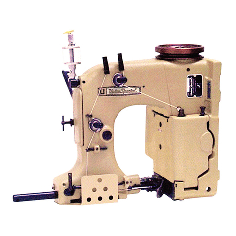
UnionSpecial 63400 Series Instruction sheet

UnionSpecial

UnionSpecial 63400 Series Instruction sheet

UnionSpecial P300-0 Series User manual

UnionSpecial

UnionSpecial P300-0 Series User manual

UnionSpecial 81500A Setup guide

UnionSpecial

UnionSpecial 81500A Setup guide

UnionSpecial BC100 Setup guide

UnionSpecial

UnionSpecial BC100 Setup guide

UnionSpecial FS322 Quick start guide

UnionSpecial

UnionSpecial FS322 Quick start guide

UnionSpecial 4500A User guide

UnionSpecial

UnionSpecial 4500A User guide

Popular Sewing Machine manuals by other brands

Pfaff 63 Instruction book

Pfaff

Pfaff 63 Instruction book

Baby Lock Aventura BLMAV Instruction and reference guide

Baby Lock

Baby Lock Aventura BLMAV Instruction and reference guide

Minerva Boskovice 525 instruction manual

Minerva Boskovice

Minerva Boskovice 525 instruction manual

Singer Futura Quartet instruction manual

Singer

Singer Futura Quartet instruction manual

Empisal Heidi 328B instruction manual

Empisal

Empisal Heidi 328B instruction manual

Consew 277RFS-3 Operation instruction & Parts list

Consew

Consew 277RFS-3 Operation instruction & Parts list

Bernette b77 user manual

Bernette

Bernette b77 user manual

Consew 345-3 parts book

Consew

Consew 345-3 parts book

JUKI MF-7500 Series Specifications

JUKI

JUKI MF-7500 Series Specifications

Singer Simple 3221 instruction manual

Singer

Singer Simple 3221 instruction manual

iSP M2000 owner's manual

iSP

iSP M2000 owner's manual

Singer 14SH744 instruction manual

Singer

Singer 14SH744 instruction manual

Singer 221 manual

Singer

Singer 221 manual

Yamato AZ8600SD instruction manual

Yamato

Yamato AZ8600SD instruction manual

Singer 211W155 Service manual

Singer

Singer 211W155 Service manual

Singer 14 U44B/244B Operator's guide

Singer

Singer 14 U44B/244B Operator's guide

Duerkopp Adler 506 installation instructions

Duerkopp Adler

Duerkopp Adler 506 installation instructions

Brother Lemair-Helvetia instruction manual

Brother

Brother Lemair-Helvetia instruction manual

manuals.online logo
manuals.online logoBrands
  • About & Mission
  • Contact us
  • Privacy Policy
  • Terms and Conditions

Copyright 2025 Manuals.Online. All Rights Reserved.