manuals.online logo
Brands
  1. Home
  2. •
  3. Brands
  4. •
  5. Universal Tool
  6. •
  7. Power Tools
  8. •
  9. Universal Tool UT8901 Specifications

Universal Tool UT8901 Specifications

Manufacturer/Supplier Product Type BPM
Cycles Per Min
Tel No Fax No(01494) 883300 (01494) 883237
Model No/Nos Serial No
Product Nett Weight
lbs
Kg
Recommended Use Of
Balancer Or Support
Recommended Hose Bore
Size - Minimum
Recommended Max.
Hose Length
Ins M/M Ft M
Foreseen Use of Tool
The tool is designed to cut sheet metal of up to 18SWG (1.2mm) in
steel and aluminium. The cutting action is generated by a
reciprocating punch working against a fixed die. In cutting the
material, metal is removed the width (1/8”) of the diameter of the
reciprocating punch, and because of this action it is possible to make
small radiused cuts or cuts across large sheets.
Use the tool only for the purpose for which it was designed. Do not
use the tool for any other purpose. Do not modify the tool for any
other purpose or for its use as a nibbler without first agreeing any
other use with the manufacturer or the manufacturer’s authorised
distributor.
Putting Into Service
Air Supply
Use a clean lubricated air supply that will give a measured air pressure
at the tool of 90 p.s.i./6.3 bar when the tool is running with the trigger
fully depressed. Use recommended hose size and length. It is
recommended that the tool is connected to the air supply as shown
in figure 1. Do not connect the tool to the air line system without
incorporating an easy to reach and operate air shut off valve. The air
supply should be lubricated. It is strongly recommended that an air
filter, regulator, lubricator (FRL) is used as shown in Figure 1 as this
will supply clean, lubricated air at the correct pressure to the tool.
Details of such equipment can be obtained from your supplier. If such
equipment is not used then the tool should be lubricated by shutting
off the air supply to the tool, depressurising the line by pressing the
trigger on the tool. Disconnect the air line and pour into the intake
Work Stations
The tool should only be
used as a handheld, hand
operated tool. It is always
recommended that the
tool is used when standing
on a solid floor. It can be
used in other positions but
before any such use, the
operator must be in a
secure position having a
firm grip and footing and
be aware of a reaction
force on the hand as result
of the tool doing work.
No
Page No 1
Nibbler
UT8901
2.03
0.92 3/8 10 30 10
3,500
Includes - Foreseen Use, Work Stations, Putting Into Service, Operating,
Dismantling, Assembly and Safety Rules
Operator Instructions Important
Read these instructions carefully before installing, operating,
servicing or repairing this tool. Keep these instructions in a safe
accessible place.
Universal Air Tool Company Limited
Unit 8
Lane End Industrial Park
High Wycombe
Bucks
HP14 3BY
Vibration Level
Test Method Tested in accordance with ISO
standards 8662 Part 1
5.2
Noise Level Sound Pressure Level 87.5 dB(A)
Test Method Tested in accordance with Pneurop
test code PN8NTC1 and ISO Standard 3744
Sound Power Level 98.1 dB(A)
Metres / Sec²
Air Pressure
Recommended Working
6.3
bar
90
PSI
Recommended Minimum
n/a
bar
n/a
PSI
Maximum
7
bar
100
PSI
Personal Safety Equipment
Use - Safety Glasses
Yes
Use - Safety Gloves
Yes
Use - Safety Boots
Use - Breathing Masks
Use - Ear Protectors
Yes
Dismantling & Assembly Instructions
Disconnect tool from air supply.
Locate motor housing (1) in a vice with soft jaws. Unscrew nibbler
head (34) from the motor housing (1) then pull out the crank shaft
(32) and the cam (33) from the nibbler head (34) and remove the 2
bearings (30) Take off the retaining ring (29) and the spacer nut (28)
then pull out the planet gear carrier (27) and remove the 3 planet
gears (26) from the internal gear (25). Tap out pin (3) to remove lever
(2). Remove valve plug (11) to take out O-ring (9) and (10) air
regulator (8) spring (7) throttle pin (6) and O`rings (5) & (4), Pull out
motor assembly from motor housing (1). To dismantle the motor
assembly, grip the front end plate (22) tightly by hand and tap the
gear end of the rotor with a non metallic or soft metal [lead or
aluminium] hammer through the front end plate (22) and bearing
(23). Remove 4 off rotor blades (21) and cylinder (19). Support rear
end plate (17) in a piece of tube with a bore size as close as possible
to the maximum diameter of the rotor and tap the non splined end
of the rotor to remove it from the rear end plate and bearing
assembly. Tap out bearing (23) from front end plate (22) and bearing
(16) from rear end plate (17).
Reassembly
Clean all parts and examine for wear before reassembling. Lightly
coat all parts in oil and pack bearings, head and gearbox with a
lithium or molybdenum based general purpose grease. Assemble in
the reverse order.
To set the Nibbler Head for Cutting
Take off nut (40) with anvil (41) then undo the Hex screw (39) on
the slide pin (37) and insert a new punch (38) the retighten the hex
screw (39) and make sure the slide pin bushing (36) is still in place,
then relocate the anvil (41) to the desired angle. Screw back the nut
(40) and its ready to cut again.
forces that may be generated whilst using the tool.
10) Use only correct spare parts. Do not improvise or make
temporary repairs.
11) Do not lock, tape, wire, etc. the on/off valve in the run position.
The trigger/lever etc. must always be free to return to the 'off'
position when it is released.
12) Always shut off the air supply to the tool, and depress the
trigger/lever etc. to exhaust air from the feed hose before fitting,
adjusting or removing the working attachment.
13) Check hose and fittings regularly for wear. Replace if necessary.
Do not carry the tool by its hose and ensure the hand is remote from
the on/off control when carrying the tool with the air supply
connected.
14) Take care against entanglement of moving parts of the tool with
clothing, ties, hair, cleaning rags, etc. This will cause the body to be
drawn towards the tool and can be very dangerous.
15) It is expected that users will adopt safe working practices and
observe all relevant legal requirements when installing, using or
maintaining the tool.
16) Do not install the tool unless an easily accessible and easily
operable on/off valve is incorporated in the air supply.
17) Take care that the tool exhaust air does not cause a problem or
blows on another person.
18) Never lay a tool down unless the working attachment has
stopped moving.
bushing a teaspoonful (5ml) of a suitable pneumatic motor lubricating
oil preferably incorporating a rust inhibitor. Reconnect tool to air
supply and run tool slowly for a few seconds to allow air to circulate
the oil. If tool is used frequently lubricate on daily basis and if tool
starts to slow or lose power.
It is recommended that the air pressure at the tool whilst the tool is
running is 90 p.s.i./6.3 bar. The tool can run at lower and higher
pressures with the maximum permitted working air pressure of 100
p.s.i./7.0 bar.
Page No 2
Safety Rules For A Nibbler
1) Read all the instructions before using this tool. All operators must
be fully trained in its use and aware of these safety rules.
2) Do not exceed the maximum working air pressure.
3) Use personal safety equipment.
4) Use only compressed air at the recommended conditions.
5) If the tool appears to malfunction remove from use immediately
and arrange for service and repair.
6) If the tool is used with a balancer or other support device ensure
that it is fixed securely.
7) Always keep hands away from the working attachment fitted to
the tool.
8) The tool is not electrically insulated. Never use the tool if there is
any chance of it coming into contact with live electricity.
9) Always when using the tool adopt a firm footing and/or position
and grip the tool firmly to be able to counteract any forces or reaction
Operating
Connect the tool to correct air supply set at the correct pressure.
Ensure that punch is operating correctly - see under
Dismantling/Assembly. Lubricate sheet to be cut with a smear of oil
to help improve life of punch and die. Allow the tool to cut - do not
force. Try to keep the tool so that the centre line of the die and punch
is at right angles to the sheet being cut.
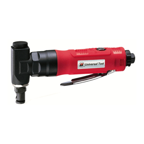
UT8901 Nibbler
Page No 3
Dec 2009 Ver 1.0
Ref No Part No Description
25 RL60225 Internal Gear
26 RL60226 Planet Gear (3)
27 RL60227 Planet Gear Plate
28 RL13628XP Spacer Nut
29 RL13629 Retainer Ring
30 RL13630 Ball Bearing (2)
31 RL60444B Spacer
32 RL13632 Crank Shaft
33 RL13633 Cam
34 RL136534SCV Nibbler Head
35 RL13635EB Head Cap (Red)
36 RL136536 Slide Pin Bushing (2)
37 RL136537 Slide Pin
38 RL136538 Punch
39 RL136539 Hex. Screw
40 RL136540 Nut
41 RL136541 Anvil
42 RL606382 Pin
48 RL60248NC Comfort Grip (Black)
NS RL136538 Punch
NS RL136541 Anvil
Ref No Part No Description
1 RL60201P Motor Housing
2 RL80512A Safety Throttle Lever (Black)
3 RL80513 Roll Pin
4 RL80504 O-Ring
5 RL80505 O-Ring
6 RL80506 Valve Stem/Throttle Pin
7 RL80507 Spring
8 RL13004 Air Regulator
9 RL80509 O-Ring
10 RL80510 O-Ring (2)
11 RL80511 Valve Plug
12 RL602121BS Air Inlet(Bsp Threaded, Metal)
13 RL80416 Muffler/Exhaust Reflector
14 RL80515 O-Ring
16 RL80417 Ball Bearing
17 RL80418 Rear End Plate
18 RL80421 Steel Ball (3)
19 RL30322 Cylinder
20 RL60220 Rotor
21 RL80420 Rotor Blade (4)
22 RL60222A Front End Plate
23 RL80524 Ball Bearing
Distributor
Notes
Page No 4
Accessories
This document may not be copied wholly or in part by anyone without the consent of the Directors of Universal Air Tool Company Limited
©Copyright of Universal Air Tool Company Limited, established in the United Kingdom, 1994
Declaration of Conformity
Universal Air Tool Company Limited
Unit 8, Lane End Industrial Park, High Wycombe, Bucks, HP14 3BY, England
declare under our sole responsibility that the product
Model UT8901 Nibbler, Serial Number
to which this declaration relates is in conformity with the following standard(s) or other normative document(s)
EN792 (Draft), EN292 Parts 1 & 2, ISO 8662 Parts 1 & 10, Pneurop PN8NTC1
following the provisions of 89/392/EEC as amended by 91/368/EEC & 93/44/EEC Directives
Place and date of issue Name and signature or equivalent marking of authorized person
Lane End D.H.Moppett (Man. Director)
Designed & Written in the U.K.

Other Universal Tool Power Tools manuals

Universal Tool UT8961-2 Manual

Universal Tool

Universal Tool UT8961-2 Manual

Universal Tool UT1011S User manual

Universal Tool

Universal Tool UT1011S User manual

Universal Tool UT8002 Specifications

Universal Tool

Universal Tool UT8002 Specifications

Universal Tool UT8630L User manual

Universal Tool

Universal Tool UT8630L User manual

Universal Tool UT1040C User manual

Universal Tool

Universal Tool UT1040C User manual

Universal Tool UT2010 User manual

Universal Tool

Universal Tool UT2010 User manual

Universal Tool UT1011C User manual

Universal Tool

Universal Tool UT1011C User manual

Universal Tool UT2003-1 User manual

Universal Tool

Universal Tool UT2003-1 User manual

Universal Tool UT2005-1 Manual

Universal Tool

Universal Tool UT2005-1 Manual

Universal Tool UT8010-1 User manual

Universal Tool

Universal Tool UT8010-1 User manual

Universal Tool UT079 Specifications

Universal Tool

Universal Tool UT079 Specifications

Universal Tool UT8892SP Series Manual

Universal Tool

Universal Tool UT8892SP Series Manual

Universal Tool UT8006 User manual

Universal Tool

Universal Tool UT8006 User manual

Universal Tool UT1010C User manual

Universal Tool

Universal Tool UT1010C User manual

Universal Tool UT2000 -1 User manual

Universal Tool

Universal Tool UT2000 -1 User manual

Universal Tool UT1520C User manual

Universal Tool

Universal Tool UT1520C User manual

Universal Tool UT8961-2NR Manual

Universal Tool

Universal Tool UT8961-2NR Manual

Universal Tool UT7520C-75 User manual

Universal Tool

Universal Tool UT7520C-75 User manual

Universal Tool UT7560C-75 User manual

Universal Tool

Universal Tool UT7560C-75 User manual

Universal Tool UT021A Specifications

Universal Tool

Universal Tool UT021A Specifications

Universal Tool UT8941 User manual

Universal Tool

Universal Tool UT8941 User manual

Universal Tool UT8862 User manual

Universal Tool

Universal Tool UT8862 User manual

Universal Tool UT9935 User manual

Universal Tool

Universal Tool UT9935 User manual

Universal Tool UT1520S User manual

Universal Tool

Universal Tool UT1520S User manual

Popular Power Tools manuals by other brands

Fieldmann FDV 210850-E manual

Fieldmann

Fieldmann FDV 210850-E manual

Hilti DX 6 manual

Hilti

Hilti DX 6 manual

Craftex CT023N owner's manual

Craftex

Craftex CT023N owner's manual

Skil 4581 CA Original instructions

Skil

Skil 4581 CA Original instructions

EINHELL TC-MG 18 Li Original operating instructions

EINHELL

EINHELL TC-MG 18 Li Original operating instructions

Sthor 78123 Operating	 instruction

Sthor

Sthor 78123 Operating instruction

Campbell Hausfeld AF010800 operating instructions

Campbell Hausfeld

Campbell Hausfeld AF010800 operating instructions

EINHELL GE-LM 36/4in1 Li operating instructions

EINHELL

EINHELL GE-LM 36/4in1 Li operating instructions

DeWalt DCS355 instruction manual

DeWalt

DeWalt DCS355 instruction manual

RIDGID K-39B Operator's manual

RIDGID

RIDGID K-39B Operator's manual

Senco PalletPro 57F Specifications

Senco

Senco PalletPro 57F Specifications

Wilton 2221VS Operating instructions & parts manual

Wilton

Wilton 2221VS Operating instructions & parts manual

Makita UH201DSAX instruction manual

Makita

Makita UH201DSAX instruction manual

Bush Hog PHDHF15 Operator's manual

Bush Hog

Bush Hog PHDHF15 Operator's manual

kincrome IGNITE K15351 manual

kincrome

kincrome IGNITE K15351 manual

BVV CK30TV3 User instructions

BVV

BVV CK30TV3 User instructions

DeWalt D25981 Original instructions

DeWalt

DeWalt D25981 Original instructions

Lux Tools STS 85 Original operating instructions

Lux Tools

Lux Tools STS 85 Original operating instructions

manuals.online logo
manuals.online logoBrands
  • About & Mission
  • Contact us
  • Privacy Policy
  • Terms and Conditions

Copyright 2025 Manuals.Online. All Rights Reserved.