manuals.online logo
Brands
  1. Home
  2. •
  3. Brands
  4. •
  5. Universal Tool
  6. •
  7. Tools
  8. •
  9. Universal Tool UT8631 Specifications

Universal Tool UT8631 Specifications

Manufacturer/Supplier Product Type
Tel No Fax No
(01494) 883300 (01494) 883237
Model No/Nos Serial No
Product Nett Weight
lbs
Kg
Recommended Use Of
Balancer Or Support Recommended Hose Bore
Size - Minimum
Recommended Max.
Hose Length
Ins M/M Ft M
Foreseen Use of the Tool
These tools are designed for the purpose of chipping and
riveting of metals and stone. In general terms a reciprocating
free piston in the cylinder of the tool imparts a blow to the chisel
or working attachment. A list of suitable equipment to use with
this tool can be provided by the manufacturer. Do not use the
tool for any other purpose than that for which it was designed
without consulting the manufacturer or the manufacturer’s
authorised representative.
Do not modify the tool for it’s use as a chipper etc. or for any
other purpose without first agreeing any such modification with
the manufacturer or the manufacturer’s authorised
representative.
Putting Into Service
Air Supply
Use a clean lubricated air supply that will give a measured air
pressure at the tool of 90 p.s.i./6.3 bar when the tool is running
with the trigger fully depressed. Use recommended hose size
and length. It is recommended that the tool is connected to the
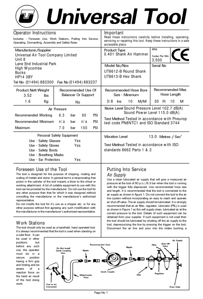
air supply as shown in figure 1. Do not connect the tool to the
air line system without incorporating an easy to reach and
operate air shut off valve. The air supply should be lubricated. It
is strongly recommended that an air filter, regulator, lubricator
(FRL) is used as shown in Figure 1 as this will supply clean,
lubricated air at the correct pressure to the tool. Details of such
equipment can be obtained from your supplier. If such
equipment is not used then the tool should be lubricated by
shutting off the air supply to the tool, depressurising the line by
pressing the trigger on the tool. Disconnect the air line and pour
Work Stations
The tool should only be used as a handheld, hand operated tool.
It is always recom-
mended that the tool
is used when stand-
ing on a solid floor. It
can be used in other
positions but before
any such use, the op-
erator must be in a
secure position hav-
ing a firm grip and
footing and be aware
of a reaction force on
the hand as result of
the tool doing work.
No
Page No 1
Chipping Hammer
UT8631
1.77 3/8 10 30 10
Includes - Foreseen Use, Work Stations, Putting Into Service,
Operating, Dismantling, Assembly and Safety Rules
Operator Instructions Important
Read these instructions carefully before installing, operating,
servicing or repairing this tool. Keep these instructions in a safe
accessible place.
Universal Air Tool Company Limited
Unit 8
Lane End Industrial Park
High Wycombe
Bucks
HP14 3BY
Vibration Level
Test Method
Tested in accordance with ISO
standards 8662 Parts 1 & 2
13.4
Metres / Sec²
3.90
Noise Level
Sound Pressure Level 89.0 dB(A)
Test Method
Tested in accordance with Pneurop
test code PN8NTC1 and ISO Standard 3744
Sound Power Level 102.0 dB(A)
Personal Safety Equipment
Use - Safety Glasses
Yes
Use - Safety Gloves
Yes
Use - Safety Boots
Use - Breathing Masks
Use - Ear Protectors
Yes
Air Pressure
Recommended Working
6.3
bar
90
PSI
Recommended Minimum
n/a
bar
n/a
PSI
Maximum
7.0
bar
100
PSI
Dismantling & Assembly Instructions
Disconnect tool from the air supply.
Rotate chisel cover (20) until it is possible to see ball (18)
centrally positioned in the hole in the side of chisel cover (20)
and in this position it is possible to pull out the chisel (22).
Remove snap ring (21) and slide off chisel cover (20) and
remove ball (18). Four off o-rings (19) may be carefully prised off
of cylinder body(15). Prise off lockring (17) noting how it locks
via a tang located in a slot in cylinder cap (1) and a slot in the
end of cylinder body (15). Fix the chisel (22) in a vice and locate
tool on it using the square hole in the front of the cylinder body
and with a spanner located on the flats of cylinder cap
(1)unscrew the cylinder cap assembly. Note:- when
reassembling the tool, tighten cylinder cap (1) to cylinder body
(15). Make sure that the threaded joint is tight and that a slot in
the cylinder cap (1) lines up with a slot in the cylinder body (15)
so that the lockring (17) can be refitted by inserting the tang in
matching slots. Drive out spring roll pin (8) and take off throttle
lever (7). Unscrew throttle cap (6) and remove spring (5), throttle
rod (3) and O-ring (4) from throttle rod (3). Do not press out
throttle bushing (2) unless a replacement is required. Remove
valve assembly from cylinder body (15) and pull the valve
assembly apart to separate upper main valve (13), lower main
valve (12), main valve case (10), main valve(9) and 2 off pins
(11), carefully noting and recording for re-assembly how and
where the 2 pins (11) locate. Note also at this time to replace
the valve assembly into cylinder body (15) making sure that the
two holes in the side of upper main valve (13) locate to line up
with the two slots in the outer diameter of piston sleeve (16).
Remove piston (14). Do not press out piston sleeve (16) unless
a replacement is required.
Reassembly
Clean all parts and examine for wear and replace any worn or
damaged parts with parts obtained from the manufacturer or an
authorised distributor. Coat all parts with a pneumatic tool
lubricating oil and reassemble in the reverse order.
ensure that it is fixed securely.
7) Always keep hands away from the working attachment fitted
to the tool.
8) The tool is not electrically insulated. Never use the tool if there
is any chance of it coming into contact with live electricity.
9) Always when using the tool adopt a firm footing and/or
position and grip the tool firmly to be able to counteract any
forces or reaction forces that may be generated whilst using the
tool.
10) Use only correct spare parts. Do not improvise or make
temporary repairs.
11) Do not lock, tape, wire, etc. the on/off valve in the run
position. The trigger/lever etc. must always be free to return to
the 'off' position when it is released.
12) Always shut off the air supply to the tool, and depress the
trigger/lever etc. to exhaust air from the feed hose before fitting,
adjusting or removing the working attachment.
13) Check hose and fittings regularly for wear. Replace if
necessary. Do not carry the tool by its hose and ensure the hand
is remote from the on/off control when carrying the tool with
the air supply connected.
14) Take care against entanglement of moving parts of the tool
with clothing, ties, hair, cleaning rags, etc. This will cause the
body to be drawn towards the tool and can be very dangerous.
15) It is expected that users will adopt safe working practices
and observe all relevant legal requirements when installing,
using or maintaining the tool.
16) Do not install the tool unless an easily accessible and easily
operable on/off valve is incorporated in the air supply.
17) Take care that the tool exhaust air does not cause a problem
or blows on another person.
18) Never lay a tool down unless the working attachment has
stopped moving.
19) Never point a tool at any person.
20) Use only suitable pneumatic tool lubricants. This is important
as a safeguard against the “diesel effect” i.e. explosive mixtures
firing.
21) Chisels worn/blunt at the cutting edge or shank should not
be used as such conditions promote tool breakage, reduce
efficiency and increase vibration. A chisel which breaks can
cause injury by creating unexpected movement.
22) When chipping or scaling in potentially explosive
atmospheres use spark resistant chisels usually made of
beryllium copper. Consult the manufacturer of the tool standard
chisels about sources of supply.
23) Do not store chisels etc. at freezing and below freezing
temperatures. Freezing temperatures can make hardened-tool
steels brittle which can cause breakage and lead to injury.
24) Do not start tool until steel/chisel/needles are in contact
with the working surface. Do not run tool unless retainer is fitted.
25) Always use tool with a whip hose as shown in fig 1.
26) Don’t over reach. Keep proper footing and balance at all
times.
27) Do not force the tool but allow it to cut.
28) When possible secure work with clamps or vice so both
hands are free to operate the tool.
into the air inlet a teaspoonful (5ml) of a suitable pneumatic
motor lubricating oil preferably incorporating a rust inhibitor.
Reconnect tool to air supply and run tool slowly for a few
seconds to allow air to circulate the oil. If tool is used frequently
lubricate on daily basis and if tool starts to slow or lose power.
It is recommended that the air pressure at the tool whilst the
tool is running is 90 p.s.i./6.3 bar. The tool can run at lower and
higher pressures with the maximum permitted working air
pressure of 100 p.s.i./7.0 bar.
Page No 2
Safety Rules For A Percussive Air
Hammer
1) Read all the instructions before using this tool. All operators
must be fully trained in its use and aware of these safety rules.
2) Do not exceed the maximum working air pressure.
3) Use personal safety equipment.
4) Use only compressed air at the recommended conditions.
5) If the tool appears to malfunction remove from use
immediately and arrange for service and repair.
6) If the tool is used with a balancer or other support device
Operating
Connect tool to clean supply of compressed air at
recommended pressure. Select chisel/attachment to perform
the work task and ensure that the chisel retainer is securely
fitted. Do not use tool without retainer fitted. Always ensure that
the working tool is in contact with the workpiece before
pressing the trigger. Running the tool free will reduce tool life by
placing unnecessary high loads on tool retainers and cylinders.
UT8631 Chipping Hammer
Page No 3
Mar 2005 Ver 1.2
Ref No Part No Description
1 863101 Cylinder Cap
2 863102 Throttle Bushing
3 863103 Throttle Rod
4 863104 O-ring
5 863105 Spring
6 863106 Throttle Cap
7 863107 Throttle Lever
8 863108 Spring Roll Pin
9 863109 Main Valve
10 863110 Main Valve Case
11 863111 Pin (2)
Ref No Part No Description
12 863112 Lower Main Valve
13 863113 Upper Main Valve
14 863114 Piston
15 863115 Cylinder Body
16 863116 Piston Sleeve
17 863117 Lock Ring
18 863118 Ball
19 863119 O-ring (4)
20 863120 Chisel Cover
21 863121 Snap Ring
22 863122 Chisel
Distributor
Notes
Page No 4
Accessories
This document may not be copied wholly or in part by anyone without the consent of the Directors of Universal Air Tool Company Limited
©Copyright of Universal Air Tool Company Limited, established in the United Kingdom, 1994
Declaration of Conformity
Universal Air Tool Company Limited
Unit 8, Lane End Industrial Park, High Wycombe, Bucks, HP14 3BY, England
declare under our sole responsibility that the product
Model UT8631 Chipping Hammer, Serial Number
to which this declaration relates is in conformity with the following standard(s) or other normative document(s)
EN792 (Draft), EN292 Parts 1 & 2, ISO 8662 Parts 1, 2 & 14, Pneurop PN8NTC1
following the provisions of
89/392/EEC as amended by 91/368/EEC & 93/44/EEC Directives
Place and date of issue Name and signature or equivalent marking of authorised person
Lane End D.H.Moppett (Man. Director)
Designed & Written in the U.K.

Other Universal Tool Tools manuals

Universal Tool UT5964 Specifications

Universal Tool

Universal Tool UT5964 Specifications

Universal Tool UT8646-1 User manual

Universal Tool

Universal Tool UT8646-1 User manual

Universal Tool UT021A Specifications

Universal Tool

Universal Tool UT021A Specifications

Universal Tool UT9922 User manual

Universal Tool

Universal Tool UT9922 User manual

Universal Tool UT8674-1 Manual

Universal Tool

Universal Tool UT8674-1 Manual

Universal Tool UT5964A Specifications

Universal Tool

Universal Tool UT5964A Specifications

Universal Tool UT9925 User manual

Universal Tool

Universal Tool UT9925 User manual

Universal Tool UT8617 User manual

Universal Tool

Universal Tool UT8617 User manual

Universal Tool UT9914 User manual

Universal Tool

Universal Tool UT9914 User manual

Universal Tool UT8651R Manual

Universal Tool

Universal Tool UT8651R Manual

Universal Tool UT8892HD-5 Manual

Universal Tool

Universal Tool UT8892HD-5 Manual

Universal Tool UT8910 User manual

Universal Tool

Universal Tool UT8910 User manual

Universal Tool UT8171 Specifications

Universal Tool

Universal Tool UT8171 Specifications

Universal Tool UT8355-RL User manual

Universal Tool

Universal Tool UT8355-RL User manual

Universal Tool UT5766 Specifications

Universal Tool

Universal Tool UT5766 Specifications

Universal Tool UT8895RSP Manual

Universal Tool

Universal Tool UT8895RSP Manual

Universal Tool UT8612-B Specifications

Universal Tool

Universal Tool UT8612-B Specifications

Universal Tool UT5969 Specifications

Universal Tool

Universal Tool UT5969 Specifications

Universal Tool UT8780K Specifications

Universal Tool

Universal Tool UT8780K Specifications

Universal Tool UT8806 Specifications

Universal Tool

Universal Tool UT8806 Specifications

Popular Tools manuals by other brands

PCB Piezotronics ICP 086C42 Installation and operating manual

PCB Piezotronics

PCB Piezotronics ICP 086C42 Installation and operating manual

ReelCraft 4000 Series operating instructions

ReelCraft

ReelCraft 4000 Series operating instructions

Sealey VS313 instructions

Sealey

Sealey VS313 instructions

PELA 532900 manual

PELA

PELA 532900 manual

BGS technic 8669 instruction manual

BGS technic

BGS technic 8669 instruction manual

Clarke CHT697 overview

Clarke

Clarke CHT697 overview

Yokota TOKU TCD-20 manual

Yokota

Yokota TOKU TCD-20 manual

Bosch GRO 12V-35 Original instructions

Bosch

Bosch GRO 12V-35 Original instructions

Desoutter Industrial Alligator CP0214ANBEL instruction manual

Desoutter

Desoutter Industrial Alligator CP0214ANBEL instruction manual

Leigh D4R Pro user guide

Leigh

Leigh D4R Pro user guide

Matco Tools TSB700A operating instructions

Matco Tools

Matco Tools TSB700A operating instructions

BGS technic 8921 instruction manual

BGS technic

BGS technic 8921 instruction manual

BASETech 2357759 operating instructions

BASETech

BASETech 2357759 operating instructions

Kärcher CR 5.220 manual

Kärcher

Kärcher CR 5.220 manual

Blitz GA Pkw operating instructions

Blitz

Blitz GA Pkw operating instructions

Sealey VS919 instructions

Sealey

Sealey VS919 instructions

HAEMMERLIN 340001201 owner's manual

HAEMMERLIN

HAEMMERLIN 340001201 owner's manual

BEA 200/90-838C Spare parts list/service instructions

BEA

BEA 200/90-838C Spare parts list/service instructions

manuals.online logo
manuals.online logoBrands
  • About & Mission
  • Contact us
  • Privacy Policy
  • Terms and Conditions

Copyright 2025 Manuals.Online. All Rights Reserved.