Sealey VS919 User manual

INSTRUCTIONS FOR:
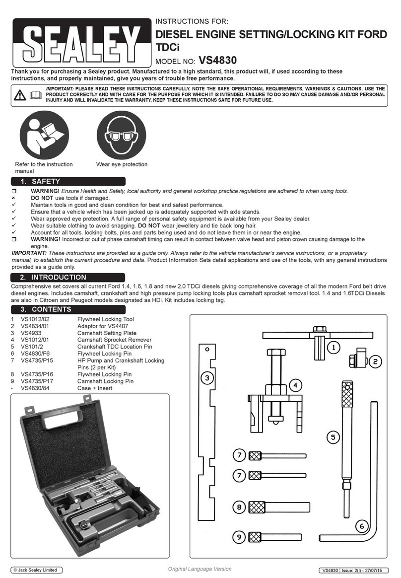
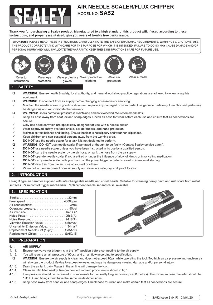
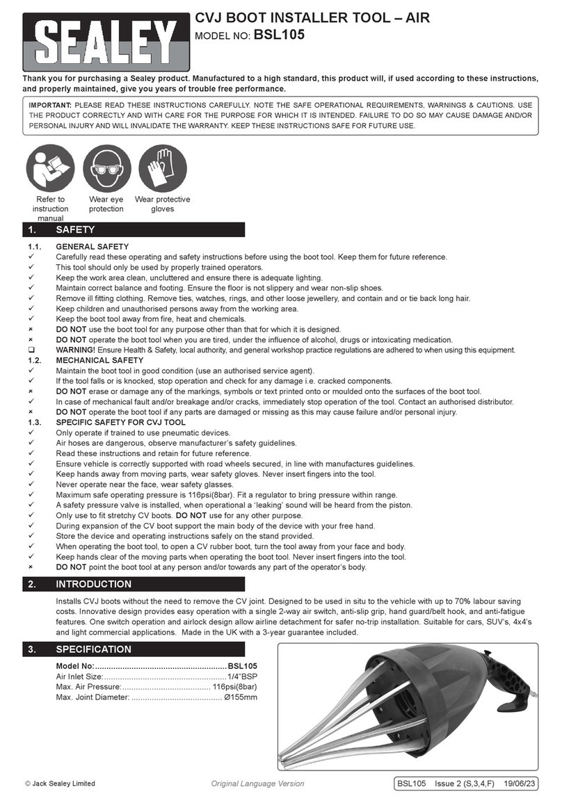
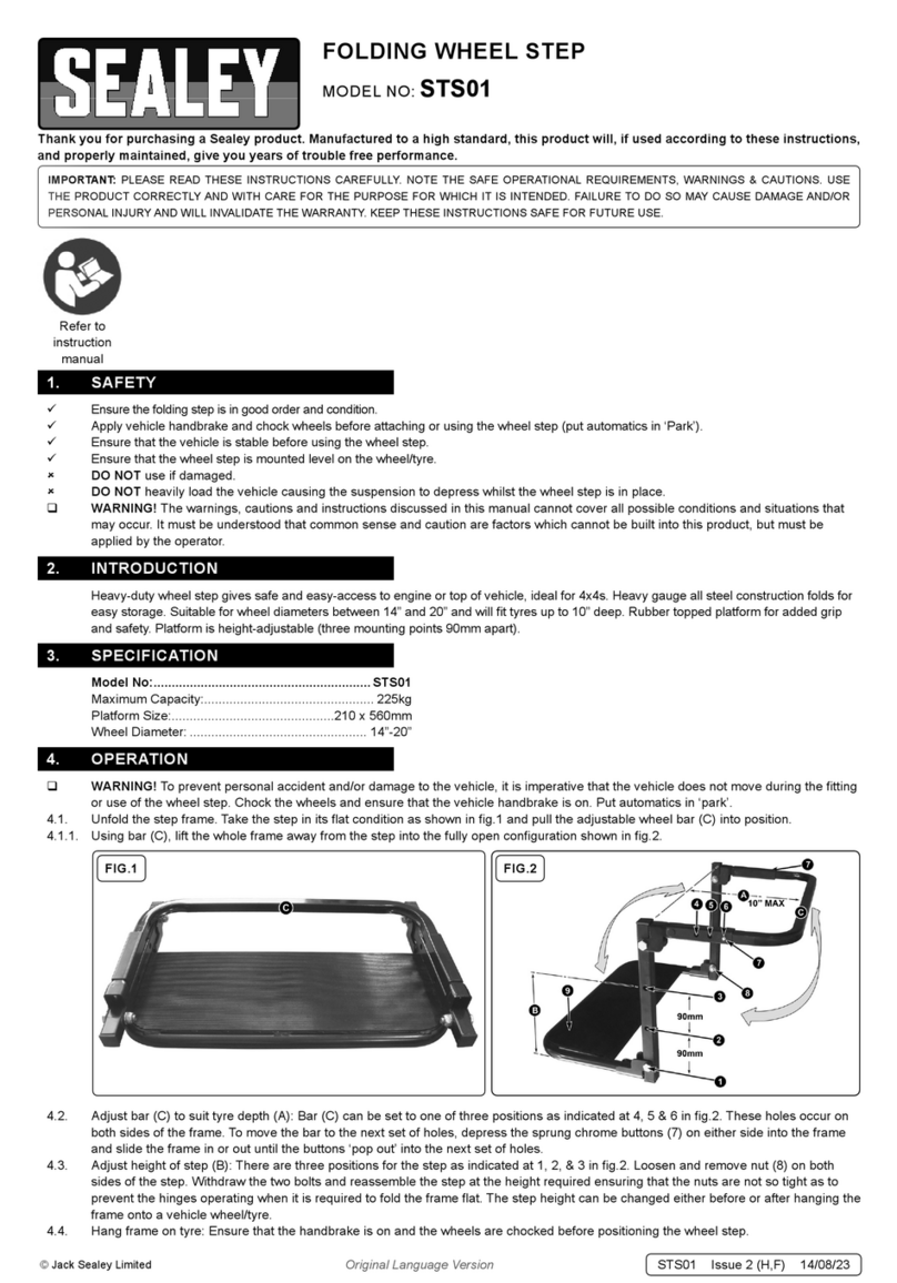
ULTRASOUND DETECTION KIT
MODEL NO: VS919
Thank you for purchasing a Sealey product. Manufactured to a high standard this product will, if used according to these instructions
and properly maintained, give you years of trouble free performance.
VS919 - 2 - 160306
1. SAFETY INSTRUCTIONS
IMPORTANT: PLEASE READ THESE INSTRUCTIONS CAREFULLY. NOTE THE SAFE OPERATIONAL REQUIREMENTS, WARNINGS & CAUTIONS.
USE THE PRODUCT CORRECTLY AND WITH CARE FOR THE PURPOSE FOR WHICH IT IS INTENDED. FAILURE TO DO SO MAY CAUSE
DAMAGE AND/OR PERSONAL INJURY AND WILL INVALIDATE THE WARRANTY. PLEASE KEEP INSTRUCTIONS SAFE FOR FUTURE USE.
1.1. GENERAL SAFETY
! WARNING! Ensure Health & Safety, local authority, and general workshop practice regulations are adhered to when using this equipment.
! WARNING! Prolonged exposure to high volumes of noise, or sudden very loud noises can result in permanent hearing loss.
#DO NOT place units or probes near high voltage items such as HT leads, spark plugs, ignition coil.
#DO NOT use the air or contact probe as a lever, pry bar, or for other unintended purposes
#DO NOT allow children to play with the equipment.
$Ensure units, probes and headphone leads do not contact moving parts.
$When not in use switch off the equipment and store in a safe, dry, childproof area and for prolonged storage remove batteries.
$Always remember the receiver and probes are an extension of your hand. Keep the probes and hands a safe distance from moving
parts and electrical areas.
$Please dispose of batteries in a way dictated by your local laws.
$Wearing headphones hinders ones ability to listen to your surroundings
$The unit is not waterproof and should be protected from the elements
$The VS919 is rugged but still a precision instrument. Avoid rough handling.
$The carrying case should be used whenever possible for protection and transportation
$Keep the equipment clean for best and safest performance.
AThe Receiver unit - an easy-to-use unit incorporating audio
feedback and a visual indicator for intensity of signal.
The receiver has a permanently fixed directional receiver
port, 3.5 mm stereo jack port, an on/off switch and controls
for setting the sensitivity and bandwidth of the unit.
B The Transmitter unit sends out a 40 kHz pulse for use in
testing seal integrity in a non-pressurised vessel. The pulse
can be adjusted to various patterns. It is powered by internal
battery.
C Anodised 300mm air probe
D Anodised precision length contact probe.
E Full-sized headphone set with 3.5 mm stereo jack.
Carrying case for storage and transportation (not shown)
TECHNICAL SPECIFICATIONS for RECEIVER UNIT
Dimensions: Width: 70mm
Depth: 25mm
Length: 140mm
Weight: 150g
Power Consumption: 26 mA, typical
Frequency Response: 36 kHz-44 kHz
Circuitry: Solid State
Headphones: Full-Sized with 3.0 metre lead
Operating temp. Range: -10 to +60 °C
Improve diagnoses and preventative maintenance by ‘listening’ to ultrasound. Small defects, leaks etc, emit ultrasound, and the detector
converts the ultrasound into an audible signal. Ultrasound is highly directional, making pinpointing the source very much easier than when
listening to normally audible sounds. As well as locating defects in mechanical components and gas and hydraulic systems the detector can
also pick up the ultrasound from HT leaks and other sources of arcing. The ultrasound transmitter, when placed inside a vehicle, allows leaks
around seals to be pinpointed by the detector. Supplied with headphones and two extension probes. Kit supplied in storage/carry case.
2. INTRODUCTION
3. CONTENTS & SPECIFICATION
01284 757500
01284 703534 sales@sealey.co.uk
Sole UK Distributor
Sealey Group,
Bury St. Edmunds, Suffolk.
www.sealey.co.uk
Web
email
NOTE: It is our policy to continually improve products and as such we reserve the right to alter data, specifications and component parts without prior notice.
IMPORTANT: No liability is accepted for incorrect use of this product.
WARRANTY: Guarantee is 12 months from purchase date, proof of which will be required for any claim.
INFORMATION: For a copy of our catalogue and latest promotions call us on 01284 757525 and leave your full name, address and postcode.

WHY USE ULTRASONICS?
It is commonly known that faults, malfunctions, and/or flaws in mechanical, electrical, and pneumatic devices, as well as manufactured
container type objects, start as small defects or leaks. These defects are of such relatively small size that the sounds they produce are above
the range of human hearing and are not detectable aurally. Most commonly, these faults manifest themselves in the
38 kHz to 43 kHz range. These frequencies fall within the spectrum of frequencies generally referred to as being in the ultrasonic range. It is
of great use to be able to hear these ultrasonic emissions from these faults in order to be aware of imminent problems. Since these sounds
are above the normal level of hearing, a device that can transform or convert the ultrasound to an audible level has been produced to answer
this need in a cost justifiable manner with high quality results. To employ the ultrasound methodology in a usable manner, it is imperative the
listener be able to have access to an audible sound that bears a resemblance to the natural sound of the defect. That is to say, a mechanical
bearing with a defective ball should sound like such. Likewise, a microscopic leak in a compressed air system should sound like a gas leak.
Simply converting the ultrasound frequencies to audible frequencies is not sufficient with regard to rendering a usable signal.
It is for this reason that the VS919 Ultrasonic Detection Kit incorporates a process whereby the audible signal bears a close likeness to the
natural incoming sample. This range of sounds is at twice the upper frequency of normal human hearing, 20 kHz. The VS919 uses a
technology called heterodyning to convert the ultrasonic range into the audible range. Since this unit is tuned to listen to the ultrasonic range,
it is unaffected by everyday sounds such as wind, voices, and traffic which can further hinder the technician’s ability to listen for a potential
problem. The VS919 also incorporates AGC (automatic gain control), which allows one to study ultrasonic sounds associated with the roar of
a valve leak or literally the blink of an eye. AGC stops the need for high/low sensitivity switches by allowing the internal circuitry to seek the
optimum level of gain for the given situation. This ultimately allows the VS919 to be picked up and learned immediately without having to
concentrate on obtaining the correct settings.
The ultrasound detection kit is extremely effective yet easy to use, allowing the technician to concentrate on analysing the problem and not on
the operation of the instrument. Using the mechanical bearing example, should a ball within the bearing develop a small pit, this small defect
will emit ultrasonic evidence of its existence. This ultrasonically emitted indicator goes undetected by the human ear. The defective equipment
remains in service and the fault worsens over time. Eventually, the fault will increase to such a size that its resonant frequency descends into
the audible range. At this point, prudent maintenance personnel will repair the fault hopefully before it has caused damage to related
equipment and/or systems. The utility of the ultrasound detection products is that had one listened to the initial small fault, it would have
sounded like the consequent sound that was emitted by the fully defective device or object - It is this ability of this instrument that sets it apart
from those that lack the ability to convert ultrasonic frequencies into audible frequencies while retaining the same timbre and/or nature of the
sound.
The directional aspect of ultrasonic waves allows one to isolate a suspect signature sound from other background noises and detect its exact
location. This sound analysis can be used for efficiently investigating five major areas of repair and preventive maintenance in the automotive,
industrial, and trade businesses:-
1) Air leaks - Both vacuum and compressed air leaks create an energy packet or wave front which can result in an ultrasonic
emission with a differential of 1 lb/sq.in. and/or a hole down to 1/200th inch.
2) Gas and liquid turbulence - Turbulence associated with steam trap and internal valve leaks, cavitation, and blockages in liquid and
air/gas lines.
3) Electrical discharge - Electrical discharge associated with insulation breakdown, tracking, corona, and arcing.
4) Mechanical wear - State of mechanical wear in bearing and race assemblies, shafts, and gears (indicating the state of lubrication).
5) Sound generation - Can be used in conjunction with sound generators to detect container cracks and seals, door seals and
compartments. (The transmitter is matched to the receiver’s peak response.)
VS919 ULTRASONIC DETECTION KIT OVERVIEW
The VS919 is a unique item of diagnostic test equipment that has achieved outstanding results in reducing downtime and maintenance related
costs. Through the detection of ultrasonic sound, the VS919 is used to inspect and check such items as ignition systems, vacuum problems,
air brake systems, bearings, gear trains, cam and tappet assemblies, internal combustion engine valve gear and piston blow-by, gaseous
piping and ducting seals in refrigerated van bodies, air ducts, hydraulic systems, A/C system Freon leaks, and many other components.
Except for their frequencies, ultrasonic waves are exactly the same as their audible counterparts. Audible sound will propagate and compound
itself through equipment making it difficult to locate the source even with a stethoscope. Because ultrasonic waves are not as penetrating as
those of lower audible frequencies, it is much easier to pinpoint the source of the sound and there is usually less noise interference.
Conversation and most background noises are normally absent. Extremely minute sounds can therefore be detected, analysed, and exactly
located. The energy is amplified by the self-contained circuitry and converted either to sounds, which can be heard through headphones, or
intensity reading on an LED indicator. The ultrasonic transmitter is used with the receiver to check for faulty seals in cabs or trailers, or other
non-pressured enclosures.
Both the air and contact probe are precision parts and have been designed to optimise the response of the VS919 receiver when needed. The
12" air probe serves to extend reach or to facilitate in isolating a leak among multiple suspect areas. Do not modify the probes in any way and
never use the probes for other than described in this manual. The port openings of the receiver and transmitter contain a precision transducer.
During use, guard against any foreign matter from entering these areas
Batteries and replacement - Both the receiver and transmitter use one PP9 battery each. Zinc or Alkaline are preferred. To replace the battery
in the receiver, the protective rubber boot has to be removed first. The rubber boot is easier to remove when warm because it is more flexible.
To remove, push the bottom edge of the boot off of the inner enclosure and pull enclosure out. Please observe polarity. Replace boot in
reverse manner. When replacing the transmitter battery, be careful not to strain or pinch wires. Always remove battery during a period of long
storage.
The transmitter and receiver have been tuned at our factory and should require no re-calibration under normal conditions during their life.
The LED indicator allows you to home in on a steady source of ultrasonic sound, as in locating an air or vacuum leak or using the transmitter.
Simply watch for a rise or drop in the bar levels on the LED indicator to locate the source of the problem.
The transmitter emits a warble output centred at 40kHz, this output cannot be heard by the human ear. If the red indicator is on,
the unit is transmitting.
4. OVERVIEW
VS919 - 2 - 160306

BASIC OPERATIONAL PROCEDURES
RECEIVER
5.1. Put headphones on while being aware of the headphone cord location.
5.2. Plug the headphone jack into the socket located on the face of the panel.
5.3. Screw either the air probe or contact probe into the receiver port. Refer to the Typical Scanning section for optimum probe choice.
5.4. Press down the power button to turn the unit on and watch for the LED indicator to settle to the bottom position. Turn up the volume
until you can just hear the background noise (hiss). Please Note, Increasing the volume does not increase the units detection
sensitivity. Setting the volume control too high can lead to operator fatigue.
5.5. When using the air probe, point the probe in the direction of your free hand while lightly rubbing your forefinger and thumb together
about two feet away. The response should be the sound of sandpaper on wood. You can vary the distance and increase/decrease the
level of volume accordingly. While performing this function, become familiar with the directional sensitivity of the probe while sweeping
the probe past your fingers at various distances. If using the contact probe, adjust the sensitivity while lightly rubbing your finger along
the tip of the rod.
5.6. The centre two buttons allow the user to listen to either a wide or narrow bandwidth.
5.7. The receiver has an “Auto Switch Off” feature which activates after four minutes.
TRANSMITTER
5.8. To switch on the transmitter, push and hold the power button until the green LED illuminates. This will produce a constant frequency
output (single flash).
5.9. Pushing the button again will produce a two tone frequency output (double flash).
5.10. Pushing the button a third time will produce a pulsing single tone frequency output (triple flash).
5.11. Pushing the button a fourth time will produce a pulsed higher frequency output (quadruple flash).
5.12. Pushing the button again will set the unit back to the first mode (single flash).
5.13. If the battery is low then the LED will turn red.
5.14. To switch off the unit, press and hold down the button until the LED switches off.
5.15. The transmitter has an “Auto Switch Off” feature which activates after five minutes.
TYPICAL SCANNING METHODS/TIPS
The VS919 provides information in two ways: qualitative, through the ability to "hear" the signature ultrasounds produced by various types of
equipment and the ability to see the feedback level on a graduated LED indicator.
The air and contact probes are used to optimise the response depending on the type of inspection. The air probe is best used for detecting
ultrasounds associated with a pressure leak or an electrical corona, while the contact probe is best to detect the ultrasounds generated from
within a casing such as in a gear, bearing, valve or steam trap housing.
5. OPERATING INSTRUCTIONS
Fig.2.
Fig.3.
Fig.1.
MECHANICAL MALFUNCTIONS
Fig.1. shows a typical use to inspect a potential wheel bearing problem with the VS919. In this case the air probe is used, the wheel is being
turned while listening for the sound of the bearings. The tip of the probe is kept 2-3 inches from the inspection area. Response can sometimes
be optimised by removing the wheel and using the contact probe to touch the stationary centre hub. Inner and outer bearing sounds can be
isolated by contacting the inner and outer side of the spindle The VS919 is very useful in monitoring the state of the bearings, rotors, and
armature in a motor housing such as pictured in Fig.2. Because the housing encloses the moving parts, monitoring with the receiver is best by
making contact with the outside housing with the contact probe. All sound waves conduct best through materials such as metal and the
contact probe will optimise the listening response. The contact probe is also used for investigating fuel injectors in the same manner. Touch
the tip of the metal probe to the surface area being tested.
ELECTRICAL CORONA DISCHARGE
The VS919 can detect electrical coronas due to insulation breakdown or other problems.
Fig.3. shows a typical application using the VS919 to inspect possible electrical and corona
discharge associated with power switch and breaker boxes.
As with all potentially dangerous situations, use caution. Only use the air probe when
inspecting electrical conditions and keep a safe distance between the air probe tip and the
metal panel surfaces.
The receiver is highly sensitive to picking up the voltage breakdowns described The
resultant ultrasonic sound has been described as sounding like “frying bacon."
VS919 - 2 - 160306
PRESSURISED LEAKS
Applications for pressurised type inspections include compressed air or gas of any kind, air brake systems, pipes/lines,
steam systems, water lines, manifolds, and likewise all vacuum systems (fig.4.). Note: Ultrasonic detection relies on detecting the sounds
associated with the turbulence of the fluid or gas exiting a hole or orifice under a differential pressure. It is independent of the type of
gas or fluid. The receiver will readily detect air and vacuum leaks typically caused by bad gaskets, cracks in pipes, and worn valve seats
(right). As with all new inspection technologies nothing substitutes for the importance of practice in listening to the differences between good
and bad components in their real life "ultrasonic" application.
NON-PRESSURISED LEAKS
Non-pressurised vessels or containers cannot generate ultrasonic sounds. The supplied transmitter is used to broadcast an ultrasonic
noise which is optimised to the frequency response of the receiver. Some examples are: pin hole leaks, tanks, HVAC, seals, windshields,
weather stripping, and whole house integrity.
1. Turn on the transmitter and place in the enclosed environment to be evaluated. The transmitter will fill the interior with a piercing
warbling sound. Note: Since the output is in the ultrasonic range, you will not hear it without the receiver.
2. Walk around the exterior of the enclosed environment while sweeping the receiver around the suspect areas (fig.5.). Compromised
areas will be revealed by the change in tone and intensity both audibly and visibly by watching the changes on the LED indicator.
USING THE LED INDICATOR FOR LOCATING LEAKS
Please note that the volume control is independent of the LED indicator. Depending on the amount of ultrasonic signature being detected, you
can use both the level of intensity on the LED indicator and the audible amount of sound through the headphones. As you get closer to the
problem decrease the volume. As the sound gets louder, repeat the process until you have pinpointed the location.
While scanning in a side to side pattern with the receiver, watch the level of the LED indicator. Keep the receiver pointing in the direction of the
highest bar. Please note that with minute leaks, the LED indicator may not move up from the first position. In this situation, use the audible
signal as discussed above.
AUTOMOTIVE MAINTENANCE APPLICATIONS
ENGINE MECHANICAL:
Finding vacuum leaks, you will hear a hissing noise as soon as you point the receiver unit under the bonnet. Place the hollow probe on the
unit and listen and watch the LED indicator and you can pinpoint the location of the leak fast and easily.
Finding engine noises. The receiver will locate those engine noises and let you find where they are truly coming from. Ultrasound does not
transfer within engine components due to the directional characteristics of ultrasound. Use the solid contact probe.
ELECTRICAL SYSTEMS:
Separations in high-tension spark plug wire conductors can be quickly identified from the corona discharge "snapping" sound emitted. The
same applies to arcing within electrical motors and accessories. Also listen to connection points for the "snapping" or "frying bacon" sound.
This is a sound a poor connection makes under electrical load. Circuits are best tested under operation and full load.
The receiver is also good at locating short circuits. Shorts give off a "frying" or "snapping" sound also. As you are checking for shorts or
connection problems, try to wiggle the wiring. Use the hollow probe for this test.
AIR CONDITIONING SYSTEMS:
You can use the unit in one of three ways to find the problem. Use the hollow probe for this test.
1. Since most faulty Air Conditioning systems will be empty of Freon, pressurise the system with Nitrogen to about 150 to 250 psi and
then listen for the leak using the hollow probe. This method is also great for evaporator leaks inside a car. On really slow leaks,
while the system is under pressure (250psi), spray a soap solution on the A/C components and lines and you will hear the bubbles as
they escape and pop from the system. Most of the time, you can hear them from more than 3 feet away.
2. You can also pull a vacuum on the system and listen for ultrasound air sucking into the system.
3. Place the flexible hose onto the transmitter and inject ultrasound into the A/C system. You can inject the sound into the service port
into the system. The short ultrasound wave will escape were the leak is occurring. The ultrasound wave is so short that it will escape
from an opening 1/20th the thickness of a human hair.
IGNITION SYSTEMS:
This is by far the best and quickest method for diagnosing modern Coil Over Plug (COP) systems. You will hear the snapping of the plugs
firing in the headset. After some experience testing ignition systems, you can tell if you have a plug or wire problem by the sound alone. When
checking make sure you listen at both ends of the plug wire if you can to determine the problem area. Use the solid probe for this test.
Fig.4. Fig.5.
VS919 - 2 - 160306

INJECTORS
Place the solid probe onto the injector to test and listen while the engine is running. You can hear the injector working and should also be able
to hear the fuel flow. You may also want to shut the engine off and listen to make sure that the injector is not leaking fuel past the injector
nozzles. When fuel is flowing, it will create a rushing noise in the headset. A good clean injector will make a sharp ringing clicking tone, while a
dirty injector will have a muffled clicking tone.
AIR BRAKE SYSTEM:
The receiver can help locate leaks quickly in both vacuum assisted and air brake systems. In many cases leaks can be detected from a
considerable distance. After building up full pressure (Air Brakes), a casual sweep of the vehicle from one end to the other using the receiver
can often locate the leak. Use of the headphones will also reduce noise interference from the shop. If the first sweep does not locate the leak,
trace out the entire air system piping at close range (1-2 feet) with the receiver. Once the general area of the leak has been determined, the
receiver probe is very useful to pinpoint the exact location of the leak. For effectiveness, be sure that pressure is maintained in the brake
system during the entire search. If no leaks are discovered, check the air horn, windscreen wipers and other air-actuated equipment.
Use hollow probe for this test.
TYRES:
Sweep over the tyre with the receiver and it will normally find leaks of sufficient magnitude before they cause downtime on the road.
Use the hollow probe or use the receiver open.
LEAKING VALVES:
Leaking intake valves can be checked for defects by using the receiver and headphones with the engine running. All valves should emit a very
similar sound pattern when the probe is placed on the intake manifold opposite the intake port. A suspected valve can then be positively
checked, with the engine off, by bringing that particular cylinder to full compression and placing the probe on the valve stem. The "hiss" of
escaping gas across the valve seat will be distinctly audible on the leaking valve. Using the same procedure can check exhaust valves,
however, signal intensity will be much greater. Use the solid contact probe for this test.
COOLING SYSTEM:
The presence of air in the cooling system can cause hot spots, resulting in burned liners and heads in a very short time. Since all cooling
systems are under pressure, coolant must go out in order to allow the air to get in. Aeration detection equipment gives the signal that air is in
the system, but not the location of the leak. Using the VS919 receiver in suspect areas, such as the head gasket, the water pump, and
injectors, will usually detect the exact source of the leak. The "bubbling" of air in the cooling system is very noisy and usually enables the
exact problem to be determined. All such tests should be conducted while the engine is idling. Internal leaks may also be pinpointed
immediately after shut off when internal pressure is at its highest point.
EXHAUST SYSTEMS:
With the engine idling, pulsation in the exhaust system can be detected with the receiver. Leak points normally give off much louder and
sharper sound. Headphones are essential for this
WHEEL BEARINGS:
A ball or roller bearing that is in good condition and adequately lubricated normally produces a soft "whirring" sound via the headphones. Lack
of lubrication introduces scraping sounds. Flat spots or nicks cause a grating or clicking noise, depending on the speed of the rotation and the
degree of damage. For the best results, the probe should touch the spindle while spinning the wheel. Use the solid probe. You can also use
the receiver open and just point at the suspect bearing.
DRIVE TRAIN BEARING AND GEARS:
By using the receiver with headphones, it is possible to determine which gear or bearing in a drive is faulty. This should be done by allowing
the drive train to run with the wheels off the ground. Use the receiver and headphones in combination to discover the point of greatest
noise generation. Use the solid probe for this test.
HYDRAULIC SYSTEMS:
Partially blocked or bypassing valves in high-pressure hydraulic systems can be difficult and costly to find with conventional methods. Since
hydraulic systems employ very high pressures, the intensity of the ultrasonic sound given off by an internal leak is extremely high and easily
detected by the VS919 receiver. Use the hollow or solid probe for this test.
BODY WEATHER-STRIPPING. SEALS AND TANKS:
The VS919 transmitter, placed inside a vehicle, tank or any enclosure, can easily locate leaks in weather-stripping, seals, or the structure
itself. This is extremely useful for inspecting storage tanks.
The VS919 Ultrasonic Detection kit will become one of the most valuable tools in your maintenance diagnostic and repair operation.
VS919 - 2 - 160306
01284 757500
01284 703534 sales@sealey.co.uk
Sole UK Distributor
Sealey Group,
Bury St. Edmunds, Suffolk.
www.sealey.co.uk
Web
email
NOTE: It is our policy to continually improve products and as such we reserve the right to alter data, specifications and component parts without prior notice.
IMPORTANT: No liability is accepted for incorrect use of this product.
WARRANTY: Guarantee is 12 months from purchase date, proof of which will be required for any claim.
INFORMATION: For a copy of our catalogue and latest promotions call us on 01284 757525 and leave your full name, address and postcode.
6. DECLARATION
Declaration of Conformity We, the sole importer into the UK, declare that the product listed here is in conformity with the following standards and directives. The construction
file for this product is held by the Manufacturer and may be inspected, by a national authority, upon request by contacting Jack Sealey Ltd
For Jack Sealey Ltd. Sole importer into the UK of Sealey
Power Tools.
Ultrasound Detection Kit Model: VS919
89/336/EEC EMC Directive
93/68/EEC Marking Directive
16th March 2006
Signed by Tim Thompson
Table of contents
Other Sealey Tools manuals

Sealey
Sealey SA660 User manual

Sealey
Sealey Premier SDL14 User manual

Sealey
Sealey VS779 User manual

Sealey
Sealey AK45X.V2 User manual

Sealey
Sealey GH60A User manual

Sealey
Sealey SA401.V2 User manual

Sealey
Sealey SA90 User manual

Sealey
Sealey VS0205 User manual

Sealey
Sealey ES1000 User manual

Sealey
Sealey RE230 User manual

Sealey
Sealey VS4910 User manual

Sealey
Sealey VS2059.V3 User manual

Sealey
Sealey Professional TOOLS SX300.V2 User manual

Sealey
Sealey VSE4787 User manual

Sealey
Sealey POWER PRODUCTS SA810 User manual

Sealey
Sealey VS1831 User manual

Sealey
Sealey FPS6.V2 User manual

Sealey
Sealey Auto Service VS392 User manual

Sealey
Sealey VSE4777.V2 User manual

Sealey
Sealey VSE5587 User manual