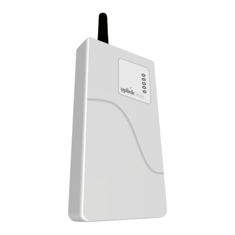
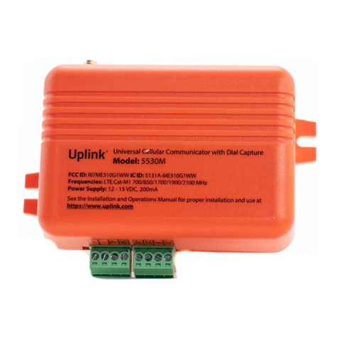
Uplink 2530 Operation manual

FOR SALES &
PRODUCT INFORMATION
Uplink
1600 Parkwood Circle
Suite 500
Atlanta, GA 30339
1-(888) 9-UPLINK
www.uplink.com
FOR TECHNICAL SUPPORT
Please visit our website at www.uplink.com.

PRIMARY
CELLULAR COMMUNICATOR
INSTALLATION &
USER’S GUIDE
PRODUCT ID # 19-25133-845
MODEL 2530

PRIMARY
CELLULAR COMMUNICATOR
©2011 Uplink Security, LLC. All rights reserved.
No part of this publication may be reproduced or used in any form without permission in
writing from Uplink. This includes electronic or mechanical means, such as photocopying,
recording, or information storage and retrieval systems. The material in this manual is
subject to change without notice.
Uplink reserves the right to make changes to any software or product to improve
reliability, function or design.
Uplink is a trademark of Uplink Security, LLC. Other product names mentioned in this
manual may be trademarks or registered trademarks of their respective companies and
are hereby acknowledged.
Guide 00-25580-845 Rev E
MODEL 2530

PRIMARY
CELLULAR COMMUNICATOR
1.
TABLE OF CONTENTS
Table of Contents ...................................................................................................................1
Introduction ..............................................................................................................................2
Key Features ..............................................................................................................................3-5
Warranty Information & Liability Waiver ........................................................................6-8
TERMS and CONDITIONS ................................................................................................6
LIMITED WARRANTY – Uplink Devices .......................................................................6
NO WARRANTY – SERVICES ...........................................................................................7
INDEMNIFICATION ............................................................................................................7
LIMITATIONS of LIABILITY ...............................................................................................8
FCC and Regulatory Compliance & Part15 .....................................................................9
FCC RF Exposure Information .............................................................................................10
Technical Support ...................................................................................................................11
Installation .................................................................................................................................12-24
A. General Considerations ..............................................................................................12
B. DIP Switch Settings ......................................................................................................12
C. LEDs ...................................................................................................................................13-14
D. Locating and Installing the 2530 ............................................................................15-17
E. Connecting the 2530 to the Alarm Panel .............................................................18-19
F. Activating the 2530 Unit .............................................................................................20-21
G. Programming and Central Station Reporting ....................................................22
H. Default Event/Email Messages ................................................................................23
I. Completing the Installation and Testing ...............................................................24
UL COMPLIANCE SECTION–Installation Recommendations ...................................25-26
A. Household Fire (UL 985-Category UTOU) ............................................................25
B. Household Burglary (UL 1023-Category NBSX, and evaluated
to UL 1635-Category AMCX) .................................................................................26
Specications ............................................................................................................................27-28
Appendix A: Contact ID, SIA, Modem IIe/IIIa/IIIa2 Event Codes ...............................29-30
Appendix B: 2530 Default Event Codes ...........................................................................31

INTRODUCTION
The Uplink MODEL 2530 Primary Cellular Communicator is an alarm and critical event
communicator designed to be used with almost any manufacturer’s alarm panels that
incorporate a digital telephone dialer. The Uplink 2530 provides a “Primary” interface to
the protected premises’ alarm panel. The primary application for this unit is an instal-
lation where no TELCO is present or available. The Uplink 2530 unit will “intercept” the
alarm panel’s digital dialer output when the panel has an event to report, and
communicate with the panel as if it were a central station alarm receiver. Once the 2530
completes a communications session with the alarm panel, it will packetize the event
data and transmit the alarm information to the designated central station receiver using
the local cellular communications network. Alarm information can be sent in Contact
ID (SIA-DC05), SIA (SIA-DC03), Modem IIe/IIIa/IIIa2 or Pulse 4+2 formats to any UL Listed
central station receiver.
The 2530 Cellular Communicator uses GSM technology to receive programming
and send event information to the central station. Its operating frequencies are in
the 850 MHz and 1900 MHz bands. The 2530 has its own built-in power supply
and the transmitter is capable of operating as a Class 4 device (2 W output) on
850 MHz and as a Class 1 device (1 Watt output) on 1900 MHz. The 2530 comes
with a dual band quarter-wave antenna covering the frequency bands of 824 - 894
MHz and 1850 - 1990 MHz.
The 2530 Cellular Communicator can be used as the primary means of communi-
cations, or as the backup communications path for the alarm panel to which it is
connected when the alarm panel has an alternate communications path such as a
digital dialer (or DACT), direct internet, etc.
2.
MODEL 2530

3.
KEY FEATURES
A. FULL DATA Reporting. Compatible with most alarm panels using Contact ID (SIA
DC-05 Standard), SIA FSK Level 1 (SIA DC-03 Standard), Modem IIe/IIIa/IIIa2 or
Pulse 4+2 digital dialer formats. All information sent by the alarm panel in either
format (Account number, zone information, User IDs, etc.) will be sent to the
central station using the GSM network.
B. Panel to 2530 Cable Supervision. Monitors continuity of the cable connecting the
panel’s telephone dialer to the 2530. This feature is activated through the website
www.uplink.com or by calling Uplink Customer Service at 1-888-9-UPLINK (1-888-987-
5465).
C. Output. The 2530 has one programmable relay output. This output can be
programmed to activate upon the occurrence of one or more of the following
Trouble conditions:
• Cellular Network Loss
• No Central Station Acknowledgement
• Low DC input Voltage
• Panel/ 2530 Cable Supervision Trouble
• Unit Disabled by Dealer Command
• Watchdog Circuit Activation
• Any Failure Condition
D. Power Source Monitoring (Low DC Input Voltage Reporting). The 2530 can report a
low input Voltage condition to the central station when its DC input voltage drops
below 10.2V DC. It will report Low input Voltage Restoral at 11.4V DC.
E. Automated Testing. The 2530 can be programmed to send an automated test
signal to the central station on a monthly, weekly or daily interval.
F. GSM Network Supervision. Supervises the local GSM network. If the unit no longer
locates the local GSM network, its output relay activates to report this trouble
condition.
(KEY FEATURES continued next page)
PRIMARY
CELLULAR COMMUNICATOR

4.
KEY FEATURES (cont.)
G. Status/Received Signal Strength LEDs. The ve LEDs indicate the current operational
status and are visible from outside the enclosure. These LEDs can be placed into
Received Signal Strength Indication mode (RSSI) to assist in selecting the optimal
mounting location for transmitting and receiving cellular radio signals.
H. Easy Service Initiation. Ships with a SIM card, with easy activations available via the
Web at www.uplink.com or by calling Uplink Customer Service at 1-888-9-UPLINK (1-888-
987-5465). Requires the central station receiver phone number and/or its IP address and
Port number.
I. Web-based Services. Available at www.uplink.com and include:
a. immediate, real-time activation
b. history of past event transmissions
c. initiation of a test report
d. the ability to query the unit and receive a real-time radio report status including
a Received Signal Strength reading
e. programming the output and other internally generated events
J. ETL Recognized. Electrical Testing Laboratories (ETL) was founded in 1896 by
Thomas Edison, and is one of the oldest product safety testing laboratories in
the world. Certication by ETL assures that the 2530 has been tested to meet
US safety and performance standards. Like the UL Mark, the ETL Mark shows
that our product has been independently tested by a Nationally Recognized
Testing Laboratory (NRTL) and that it has met the minimum requirements of
widely accepted product safety standards. The ETL Mark is recognized and
readily accepted by manufacturers, retailers, distributors and authorities having
jurisdiction (AHJs).
MODEL 2530

5.
PRIMARY
CELLULAR COMMUNICATOR
The Model 2530 unit is ETL Recognized and conforms to UL Standards 985,
1023, and 1635 for Household Fire Warning, Household Burglar Alarm, and Digital
Alarm Communicator systems. It is perfectly suited for use in any UL certicated
household alarm systems that conform to the above standards. (See the UL
Compliance Section of this manual for complete details).

WARRANTY INFORMATION
AND LIABILITY WAIVER
TERMS & CONDITIONS
These terms and conditions are a legal contact between you and the Company
and supplement (but do not supersede) the terms and conditions of any master
agreement between you and Uplink Security, LLC. (the “Company”) governing
your purchase of the Product from the Company. By using, marketing, or selling
the Product, you agree to these terms and conditions. In the event of any conict
with the master agreement, the terms and conditions of the master agreement will
control.
LIMITED WARRANTY – Uplink Devices
Uplink warrants, to parties purchasing Uplink equipment directly from Uplink, i.e.,
to its authorized distributors and to no other parties, that for 12 months following
the earlier of (a) the date of purchase or (b) the date of activation on Uplink’s
network, and in no event longer than 12 months following the date of issuance,
by Uplink, of an end of life notication, Uplink equipment will be free of defects in
materials and workmanship when installed, operated, maintained, and serviced in
strict accordance with Uplink’s and, if applicable, the manufacturer’s requirements.
If Uplink equipment fails because of a defect in materials or workmanship within
the warranty period, Uplink will, at its sole option and at no charge, repair or
replace it. Uplink’s agreement to repair (using new or reconditioned parts) or
replace (with a comparable new or reconditioned Uplink unit) is the exclusive
remedy with respect to Uplink found to be defective in materials or workmanship;
this remedy will not be deemed to have failed of its essential purpose so long as
Uplink is willing and able to repair or replace the defective unit as provided above
or, at Uplink’s sole option, to refund the purchase price paid. Parties purchasing
Uplink equipment from a distributor are referred to the distributor with respect to
any product claims they may have.
(WARRANTY INFORMATION AND LIABILITY WAIVER continued next page)
6.
MODEL 2530

7.
WARRANTY INFORMATION
AND LIABILITY WAIVER (cont.)
THE FOREGOING WARRANTY IS LIMITED AND IS THE ONLY WARRANTY OF-
FERED HEREUNDER. UPLINK MAKES NO OTHER WARRANTIES, EXPRESS
OR IMPLIED, INCLUDING, WITHOUT LIMITATION, THE IMPLIED WARRANTIES
OF MERCHANTABILITY AND FITNESS FOR A PARTICULAR PURPOSE, TITLE,
NON-INFRINGEMENT, AND NON-OBSOLESCENCE. THE FOREGOING WAR-
RANTY FURTHERMORE DOES NOT COVER UPLINK DEVICES THAT (A) HAVE
BEEN IMPROPERLY INSTALLED, MAINTAINED, OR SERVICED; (B) HAVE BEEN
TAMPERED WITH OR DEFACED; OR (C) HAVE BEEN SUBJECTED TO ABUSE
OR A HOSTILE OPERATING ENVIRONMENT.
NO WARRANTY – SERVICES
ALL SERVICES ASSOCIATED WITH UPLINK DEVICES INCLUDING, WITHOUT
LIMITATION, NETWORK CONNECTIONS ENABLED BY UPLINK, ARE PROVIDED
STRICTLY AS-IS, WITHOUT WARRANTY OF ANY KIND INCLUDING, WITH-
OUT LIMITATION, WARRANTIES OF MERCHANTABILITY AND FITNESS FOR A
PARTICULAR PURPOSE, TITLE, NON-INFRINGEMENT, NON-OBSOLESCENCE,
NON-INTERRUPTION, AND FREEDOM FROM ERROR.
Other terms and conditions and limitations of liability apply as set forth in the ap-
plicable contractual agreement with Uplink.
INDEMNIFICATION
You agree to defend, hold harmless, and indemnify the Company and its aliates
and their respective ocers, directors, employees, and agents from and against
any and all damages, liability, costs, and expenses (including, without limitation,
reasonable attorneys’ fees) arising out of or relating to (a) any claim for breach of
this Agreement by you; (b) any claim for negligence, intentional misconduct, or any
other act or omission on the part of you or your employees, agents, or representa-
tives; (c) personal injury, death, or property damage allegedly or impliedly caused
by you or your employees, agents, or representatives in connection with this
Agreement; or (d) any claim that an application of the Product or your actions in
distributing the Product or integrating it with other hardware, software, or systems
infringe the intellectual property rights of a third party.
(WARRANTY INFORMATION AND LIABILITY WAIVER continued next page)
PRIMARY
CELLULAR COMMUNICATOR
8.
WARRANTY INFORMATION
AND LIABILITY WAIVER (cont.)
LIMITATIONS of LIABILITY
THE COMPANY SHALL NOT BE LIABLE FOR ANY ACTS OR OMISSIONS
OF YOU, YOUR CUSTOMERS, END USERS OF THE PRODUCT, OR ANY
THIRD PARTY INCLUDING, WITHOUT LIMITATION, ANY ENTITY FURNISHING
EQUIPMENT, SOFTWARE, FIRMWARE, OR SERVICES TO THE COMPANY, YOU,
YOUR CUSTOMERS, OR END USERS OF THE PRODUCT, NOR SHALL THE
COMPANY BE LIABLE FOR ANY DAMAGES ATTRIBUTABLE, IN WHOLE OR IN
PART, TO THE FAILURE OF SAID EQUIPMENT, SOFTWARE, FIRMWARE, OR
SERVICES. THE COMPANY SHALL NOT BE LIABLE FOR INTERRUPTIONS IN,
OR INTERFERENCE WITH, THIRD PARTY TELECOMMUNICATIONS CARRIERS’
TRANSMISSIONS OVER WHICH THE COMPANY HAS NO CONTROL,
I.E., FOR INTERRUPTIONS OR INTERFERENCE CAUSED BY NETWORK
CONGESTION, WEATHER CONDITIONS, TERRAIN, BUILDINGS, LOCALIZED
“GAPS” IN TELECOMMUNICATIONS NETWORK COVERAGE, AND OTHER
NATURAL OR ARTIFICIAL CONDITIONS OVER WHICH THE COMPANY HAS
NO CONTROL. THE COMPANY SHALL NOT BE LIABLE FOR ANY INDIRECT,
INCIDENTAL, SPECIAL, EXEMPLARY, PUNITIVE, OR CONSEQUENTIAL
DAMAGES, INCLUDING, WITHOUT LIMITATION, LOST REVENUES, DATA, OR
PROFITS, REGARDLESS OF WHETHER THE COMPANY WAS ADVISED OF,
OR COULD HAVE REASONABLY FORESEEN, THE POSSIBILITY OF SUCH
DAMAGES. THE COMPANY SHALL NOT BE LIABLE IN THE EVENT THAT
FUTURE TECHNOLOGICAL CHANGES IMPLEMENTED BY ANY THIRD PARTY
OR GOVERNMENTAL ENTITY RENDER THE PRODUCT WHOLLY OR PARTIALLY
INOPERABLE. OTHER LIMITATIONS OF LIABILITY MAY APPLY AS PROVIDED
BY THE MASTER AGREEMENT, IF ANY, GOVERNING YOUR PURCHASE OF
THE PRODUCT FROM THE COMPANY.
MODEL 2530

9.
FCC & REGULATORY COMPLIANCE
Part 15
This device complies with Part 15 of the FCC Rules. Operation is subject to the
following two conditions: (1) this device may not cause harmful interference, and
(2) this device must accept any interference received, including interference that
may cause undesired operation.
This equipment has been tested and found to comply with the limits for a Class
B digital device, pursuant to Part 15 of the FCC Rules. These limits are designed
to provide reasonable protection against harmful interference in a residential
installation. This equipment generates, uses, and can radiate radio frequency
energy and, if not installed and used in accordance with the instructions, may
cause harmful interference to radio communications.
However, there is no guarantee that interference will not occur in a particular
installation. If this equipment does cause harmful interference to radio or television
reception, which can be determined by turning the equipment o and on, the user
is encouraged to try to correct the interference by one or more of the following
measures:
• Reorient or relocate the receiving antenna.
• Increase the separation between the equipment and receiver.
• Connect the equipment into an outlet on a circuit dierent from that to which
the receiver is connected.
• Consult the dealer or an experienced technician for help.
PRIMARY
CELLULAR COMMUNICATOR
FCC RF EXPOSURE INFORMATION
In August 1996 the Federal Communications Commission (FCC) of the United
States with its action in Report and Order FCC 96-326 adopted an updated safety
standard for human exposure to radio frequency electromagnetic energy emitted
by FCC regulated transmitters. Those guide-lines are consistent with the safety
standard previously set by both U.S. and international standards bodies. The
design of this module complies with the FCC guidelines and these international
standards. The FCC ID of this unit is TWV192513384X. For more information
about RF exposure, please visit the FCC website at www.fcc.gov.
The term “IC” before the certication/registration number only signies that the
Industry Canada Technical Specications were met. The external antennas used
for this module must provide a separation distance of at least 20cm from all
persons and must not be co-located or operating in conjunction with any other
antenna or transmitter.
10.
MODEL 2530

TECHNICAL SUPPORT
Technical Support
Technical support is available Monday through Friday, 8:00 AM to 8:00 PM ET
excluding holidays. Before calling technical support please ensure to have read
the installation guide completely. Technical support requires the caller to provide:
• Login name
• Password
• Serial number of the 2530
UPLINK Technical Support
1600 Parkwood Circle, Suite 500
Atlanta, GA 30339
888-9-Uplink (888-987-5465)
Fax: 770-693-3501
For Customer Support, call 888-987-5465, or visit www.uplink.com.
11.
PRIMARY
CELLULAR COMMUNICATOR

INSTALLATION
A. General Considerations
Determine where to mount the unit. Keep the following in mind:
a. Where to obtain the best transmitted and received signal strength for the
cellular radio. (If the installer does not have a very strong cellular signal in his area,
he may want to rst power the unit from a portable 12V DC source, switch on S4
and move the unit to a location that gives him the best signal strength.)
b. Proximity to the alarm panel and where to route the 2530’s relay output that
connects to the alarm panel unit’s input.
B. DIP Switch Settings
The 2530 has a four-position dipswitch. The dipswitches function as follows:
SWITCH NO. SETTING FUNCTION
S1: Default Load OFF Normal Operations
ON Load Defaults
S2: OTA Operation OFF OTA conguration allowed
ON OTA conguration blocked
S3: Reserved OFF N/A
ON N/A
S4: LED Function OFF Normal Operations
ON RSSI Measurements
(INSTALLATION continued next page)
12.
MODEL 2530

INSTALLATION (cont.)
C. LEDs
Normal Mode: Upon initial power up, the 5 LEDs on the 2530 will begin to function
as follows:
LED LED STATUS LED MEANING
Power LED (#1)
OFF No DC power is present
GREEN On DC Power is present
RED Flashing DC Input Voltage Low
Panel Hook Status LED (#2)
GREEN On Panel is on-hook
Flashing Panel is o-hook
Trouble LED (#3)
GREEN On Output Relay Normal
RED On Output Relay O-Normal
GSM Comm LED (#4)
GREEN On Unit registered on the network
Fast Flash Transmitted SMS message, wait for OK
from radio
Slow Flashing Waiting for an ACK from the Central Station
RED On Unit not registered or No Cellular Network
Fast Flash Registered on the GPRS network only
(No GSM)
Slow Flashing Registered on the GSM network only
(No GPRS)
(INSTALLATION continued next page)
13.
PRIMARY
CELLULAR COMMUNICATOR
INSTALLATION (cont.)
LED LED STATUS LED MEANING
Heartbeat LED (#5)
GREEN Flashing Unit is functioning normally
RED Flashing S1 is ON after reset
RSSI Mode: When the 2530 is placed in Received Signal Strength Indicator (RSSI) Mode
by turning Dipswitch S4 to ON, the ve LEDs indicate the follow signal strength
information:
RECEIVED SIGNAL STRENGTH APPEARANCE OF LEDs (#1 thru #5)
≥ -50 dBm (Good)
Unit is functioning normally
≥ -60 dBm (Good)
#1: green, solid; #2: green, solid; #3: green,
solid; #4: green, solid; #5: green, solid
≥ -70 dBm (Good)
#1: o; #2: o; #3: green, solid; #4: green,
solid; #5: green, solid
≥ -80 dBm (Good)
#1: o; #2: o; #3: o; #4: green, solid;
#5: green, solid
≥ -90 dBm (Min. Acceptable)
#1: o; #2: o; #3: o; #4: o; #5: green, solid
≥ -100 dBm (Unacceptable)
#1: o, #2: o; #3: o; #4: o; #5: green, ash
≥ -110 dBm (Unacceptable)
#1: o; #2: o; #3: o; #4: o; #5: red, solid
≤ -111 dBm (Unacceptable)
#1: o, #2: o, #3: o, #4: o, #5: red, ash
No signal
All OFF
(INSTALLATION continued next page)
14.
MODEL 2530
•••••
••••
°
•••
°°
••
°°°
•
°°°°
•
°°°°
°°°°
°°°°
°°°°°

INSTALLATION (cont.)
D. Locating and Installing the 2530
The 2530 is housed in a plastic enclosure. The installer needs to supply DC power
from the panel via the AUX output or via a separate DC power source. Input DC
current is listed in Section 9 – Specications.
After carefully considering all of the issues outlined in Section 7-A (General
Considerations), proceed as follows:
1. Separate the top and bottom of the enclosure by depressing the tab on the
bottom of the unit and then tilting the bottom of the plastic top outward and up.
2. Connect the antenna that is supplied with the 2530. The Antenna supplied may
dier from the ones depicted in the gures in this manual.
3. Go to the red, 4-position Dipswitch as shown in Figure 1 and set the dipswitch
as appropriate for this installation. (See Section 7B.)
4. Place Dipswitch #4 (S4) in the ON position. The LEDs are now operating in
RSSI Mode. Locate a good mounting position based on a good Received Signal
Strength Indication (RSSI). It is recommended that the installation location
demonstrate an RSSI of at least -80 dBm (two solid green LEDs). The
minimum acceptable RSSI is -90 dBm (1 solid green LED).
(INSTALLATION continued next page)
15.
PRIMARY
CELLULAR COMMUNICATOR
INSTALLATION (cont.)
(INSTALLATION continued next page)
16.
FIGURE 1: Model 2530 PC Board Details
MODEL 2530

INSTALLATION (cont.)
5. Position the bottom of the 2530 enclosure where it will be installed. Use four (4) #6
screws and mount the unit using the four holes in the enclosure’s plastic bottom. The
2530’s dimensions are shown in Figure 2.
6. Make sure that the unit’s antenna is connected.
7. Connect the positive (+) and negative (-) terminals of the DC Power Input to
terminals DC+ and DC - respectively on the 2530.
8. Double check to make sure that the RSSI is still showing a good signal
strength level.
9. Before connecting the alarm panel and the 2530, rst:
a. Return Dipswitch #4 (S4) to the OFF position.
b. Disconnect the Positive and Negative connections to the DC Power source.
(INSTALLATION continued next page)
17.
PRIMARY
CELLULAR COMMUNICATOR
FIGURE 2: Inside & Outside Mounting Dimensions for the 2530
CAUTION: Incorrect Connections May result in Damage to the Unit
This manual suits for next models
1
Table of contents
Other Uplink Cell Phone manuals

Uplink
Uplink 2500ez Operation manual

Uplink
Uplink 5530M Operating and maintenance instructions

Uplink
Uplink 5200 Operation manual

Uplink
Uplink 5500M Operating and maintenance instructions

Uplink
Uplink CDMAEX Operation manual

Uplink
Uplink CDMAEZ Operation manual

Uplink
Uplink 4530 Operation manual

Uplink
Uplink 4530EX User manual

Uplink
Uplink L3-5200 Operation manual

Uplink
Uplink 4550 Operation manual