5
INSTALLATION STEPS
Before beginning installation: If you are not yet an Uplink dealer, register by visiting
www.uplink.com and click on the “new dealer account” tab.
Step 1. Activate the system. The Uplink CDMAEZ operates “out of the box” with most
commercial panels. No additional programming or equipment is required. To activate
with default functions, go to www.uplink.com, or use the Uplink Installer App, or call
1-888-987-5465. Consult the Quick Installation Guide included with the CDMAEZ.
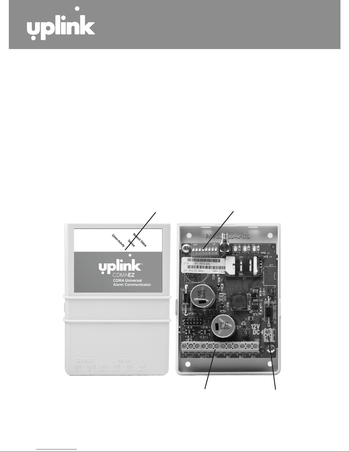
Step 2. Install the antenna on the top of the unit.
Step 3. Position the unit for maximum signal strength. Connect the unit to a 12V
DC, 500mA power supply. Be sure the area is dry and free from interference of metal
objects and obstructions.
Step 4. Determine network availability and signal strength.
a) Signals strength should be -100dB minimum. Relocated the unit or install a high-
gain antenna if necessary.
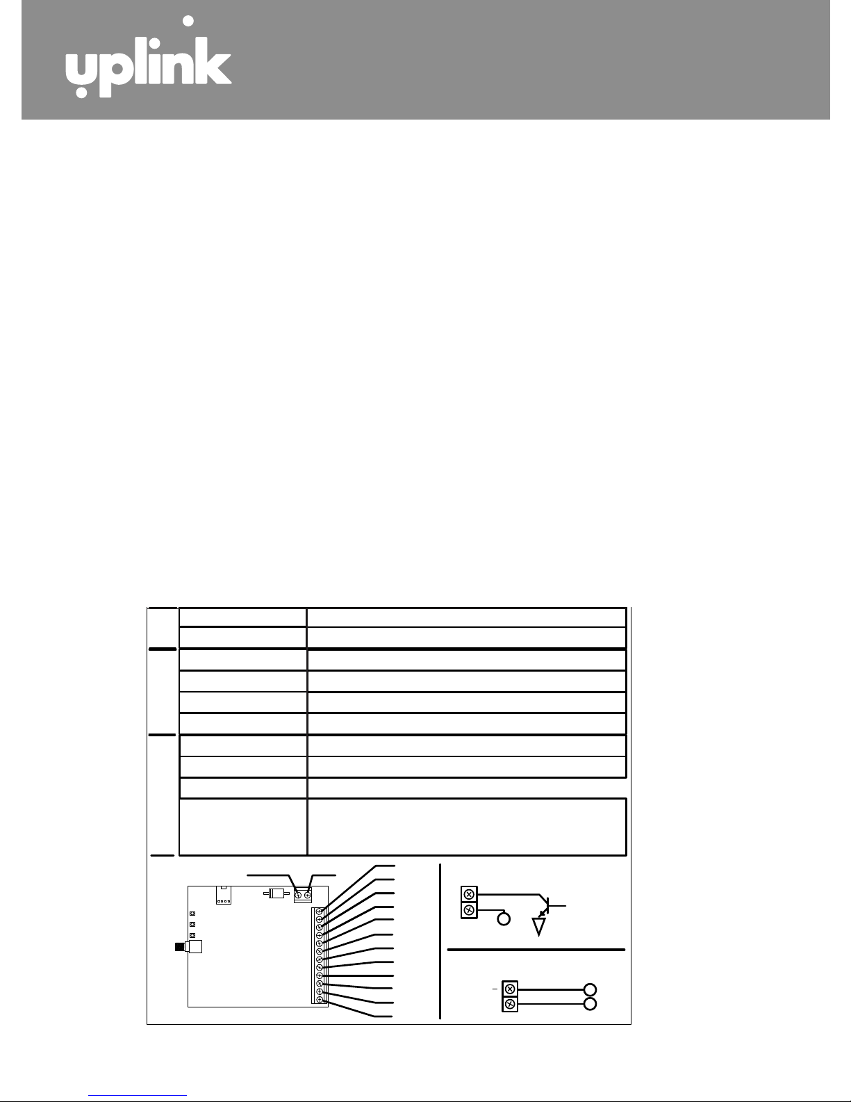
TABLE 1: LED INDICATIONS
COM
LED
NETWORK
LED
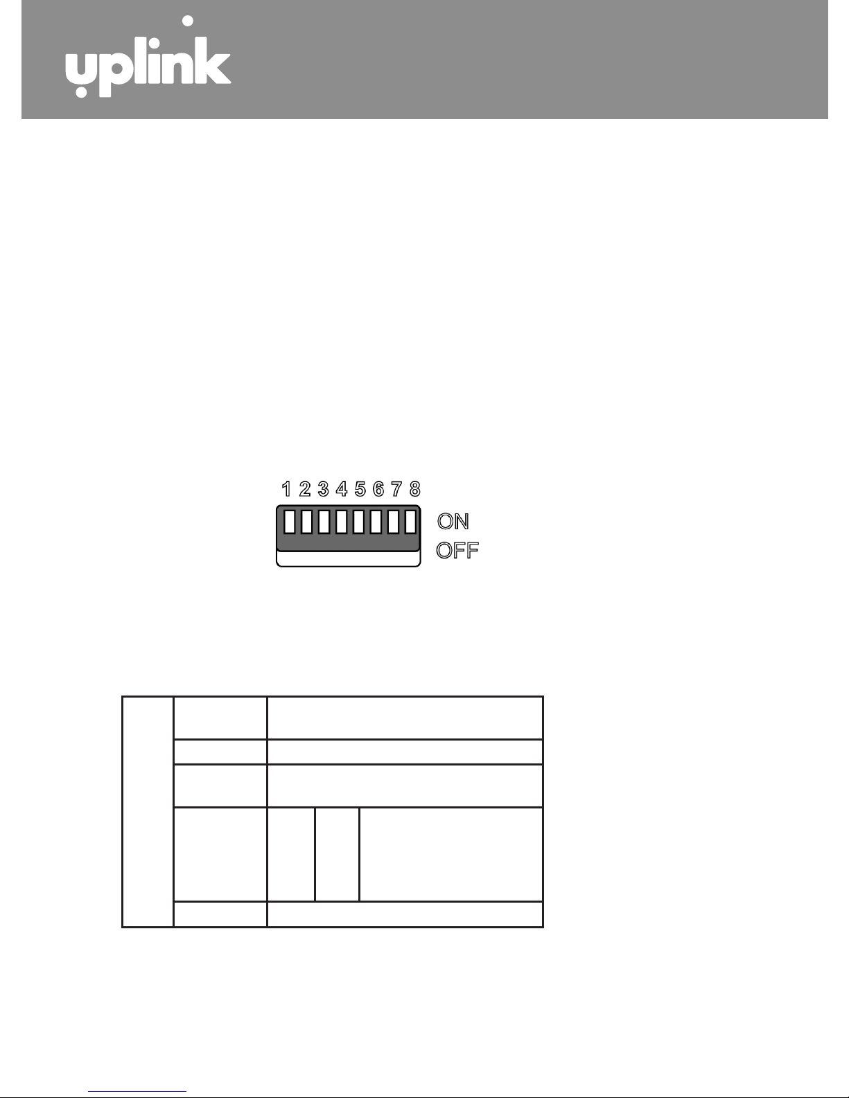
DIPSWITCH
Func5onality
SERVICE
LED
00-25593-018A
+12VDC GND IN4
IN3
IN4+
IN3+
IN2
IN1
IN2+
IN1+
OUT2
OUT2+
OUT1
OUT1+
12VDC
OUTPUT
FROMPANEL
SWITCHED12VDC
Network
GSM Service
Comms
COM
LED
NETWORK
LED
DIPSWITCH
Func5onality
SERVICE
LED
00-25593-018A
+12VDC GND IN4
IN3
IN4+
IN3+
IN2
IN1
IN2+
IN1+
OUT2
OUT2+
OUT1
OUT1+
12VDC
OUTPUT
FROMPANEL
SWITCHED12VDC
Network
GSM Service
Comms
COM
LED
NETWORK
LED
DIPSWITCH
Func5onality
SERVICE
LED
00-25593-018A
+12VDC GND IN4
IN3
IN4+
IN3+
IN2
IN1
IN2+
IN1+
OUT2
OUT2+
OUT1
OUT1+
12VDC
OUTPUT
FROMPANEL
SWITCHED12VDC
Network
GSM Service
Comms
COM
LED
NETWORK
LED
DIPSWITCH
Func5onality
SERVICE
LED
00-25593-018A
+12VDC GND IN4
IN3
IN4+
IN3+
IN2
IN1
IN2+
IN1+
OUT2
OUT2+
OUT1
OUT1+
12VDC
OUTPUT
FROMPANEL
SWITCHED12VDC
Network
GSM Service
Comms
COM
LED
NETWORK
LED
DIPSWITCH
Func5onality
SERVICE
LED
00-25593-018A
+12VDC GND IN4
IN3
IN4+
IN3+
IN2
IN1
IN2+
IN1+
OUT2
OUT2+
OUT1
OUT1+
12VDC
OUTPUT
FROMPANEL
SWITCHED12VDC
Network
GSM Service
Comms