4 5
BEFORE YOU BEGIN
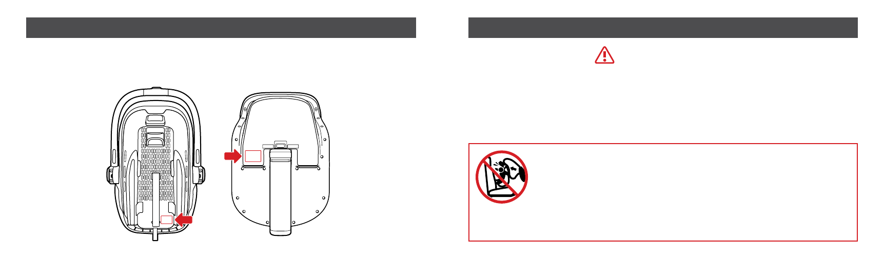
REGISTRATION
Model Number:
Manufactured Date:
Expiration Date:
TAKE A MOMENT TO FILL OUT THE ABOVE INFORMATION.
Information can be found on the manufacture labels or engraved
on the underside of the carrier.
Child restraints can be recalled for a variety of safety reasons.
You MUST register this restraint to be reached in a recall.
end your name, address, email address if available and
the restraint’s model number and manufacturing date to
276 Weymouth Street, Rockland, MA 02370 or call (844) 823-3132
or register online at: uppababy.com/registration/carseat. For recall information,
call the U.S. Government’s Vehicle Safety Hotline at 1-888-327-4236
(TTY: 1-800-424-9153), or go online to nhtsa.gov.
CERTIFICATION
This Child Restraint
system conforms to all
applicable Federal Motor Vehicle
Safety Standards (FMVSS).
This Child Restraint
is certified for aircraft
use. UPPAbaby and the
Federal Aviation Administration (FAA)
strongly urge you to secure your
child in a Child Restraint system (CRS)
or device for the duration of your
flight. This product is designed and
manufactured to comply with ASTM
2050 Standard Consumer Safety
Specification for Hand Held Carriers
and is JPMA Certified.
CHILD USE RECOMMENDATIONS
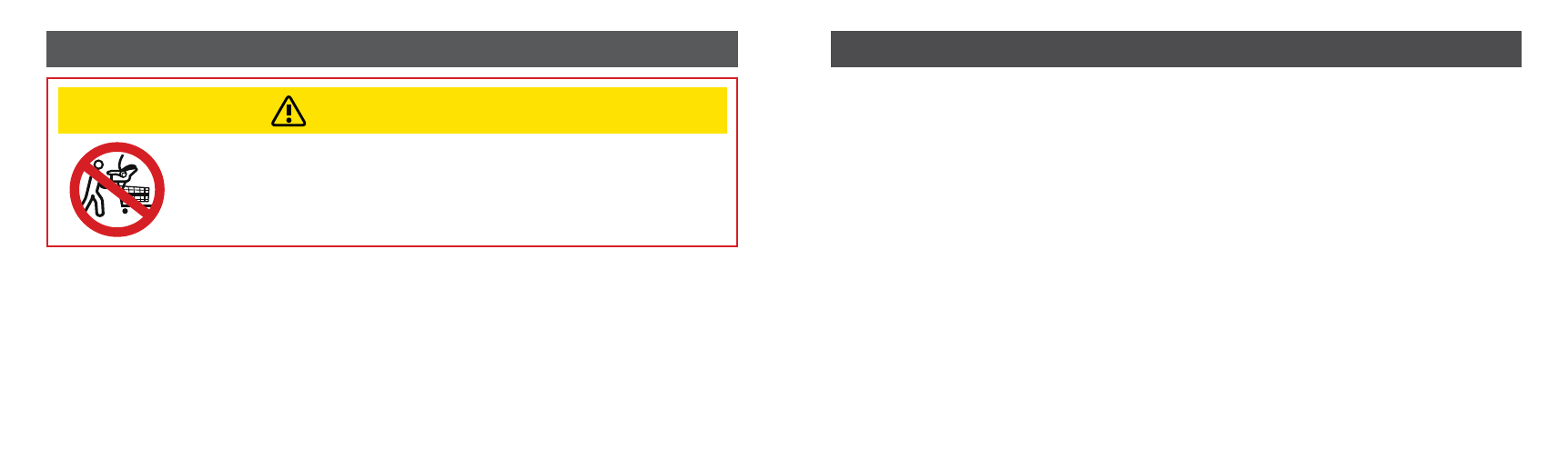
Children should remain rear-facing for as long as possible.
UPPAbaby advises that all infants and toddlers should ride in a rear-facing car safety seat (CSS) as long as possible, until they
reach the highest weight or height allowed by their CSS’s manufacturer. This child restraint is for use by children who meet
BOTH requirements below:
WEIGHT REQUIREMENTS: 4 – 35 lbs (1.8 – 15.9 kg)
HEIGHT REQUIREMENTS: 32 in (81.3 cm) or less
The Infant Insert is designed for children who weigh: 4 – 11 lbs (1.8 – 5 kg)
The top of the child’s head should not
be less than 1" from the top of the
headrest when in its highest position.
The headrest should be positioned at the child’s
shoulders to ensure proper fit of the harness.
The headrest can lightly touch the shoulders
and allow at most 1" of space between child’s
shoulders and headrest.
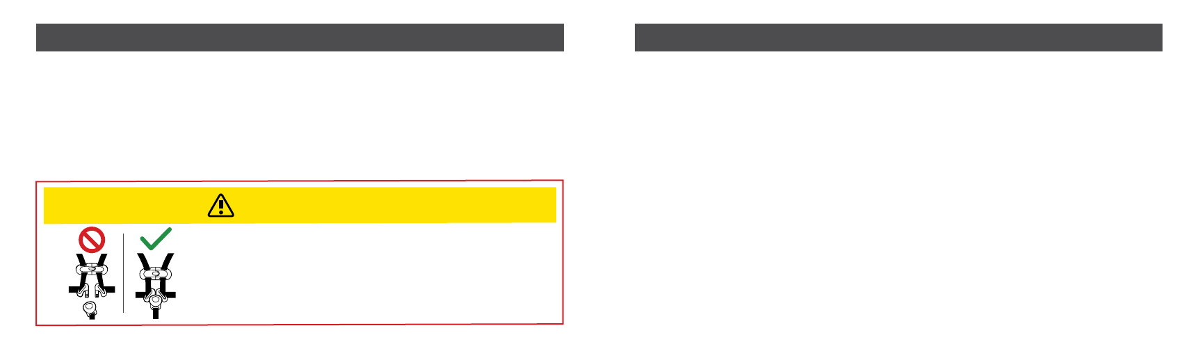
Retainer clip must be at armpit level
and harness straps should be
snug .
1"
1"
BEFORE YOU BEGIN