urmet domus IPerTalk 1375/10 Manual

2DS1375-020C
INDEX
1. GENERAL DESCRIPTION................................................................................................................................. 5
2. DESCRIPTION OF COMPONENTS .................................................................................................................. 5
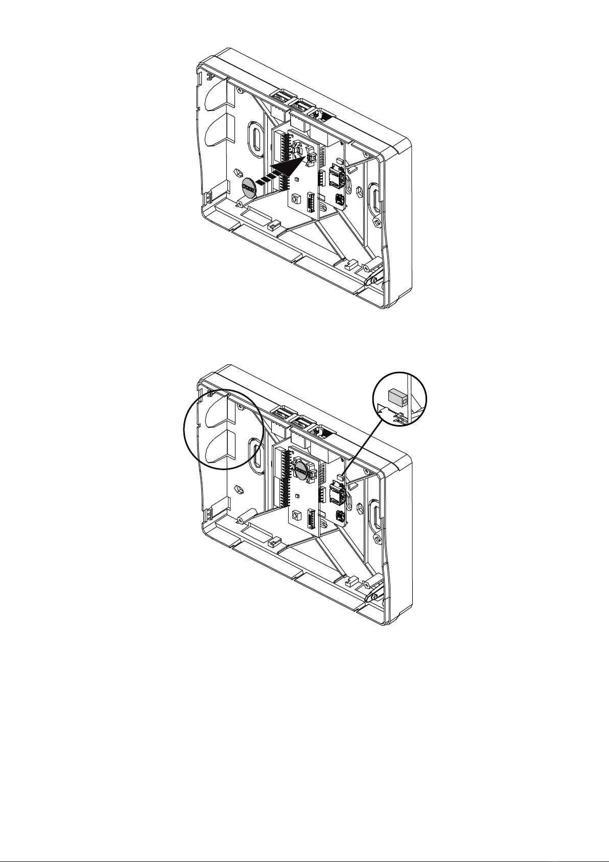
3. INSTALLATION ................................................................................................................................................. 6
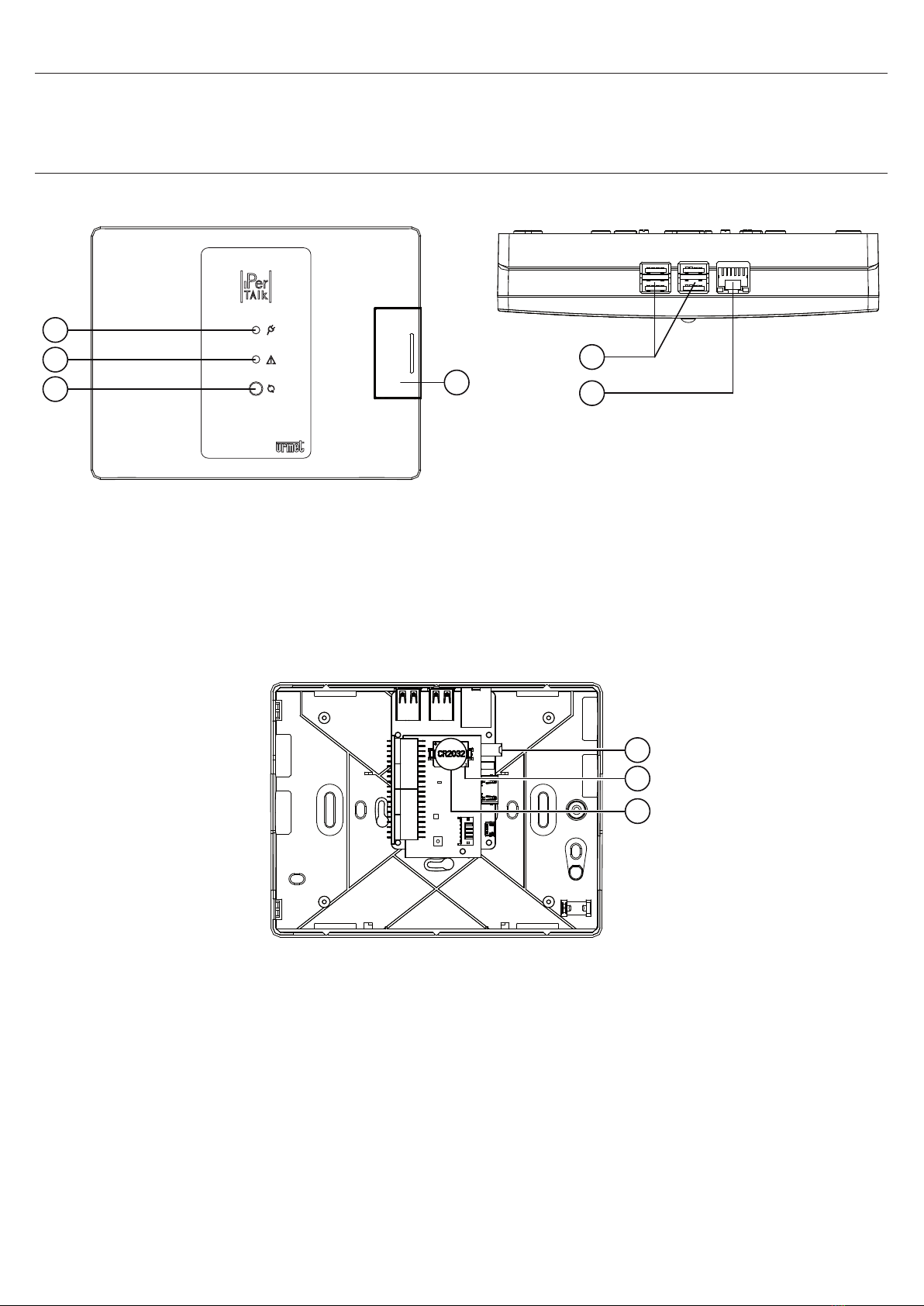
4. DESCRIPTION OF LEDS, CONNECTORS AND BUTTONS ............................................................................. 8
4.1 POWER LED (1)..................................................................................................................................... 8
4.2 STATUS LED (2).................................................................................................................................... 8
4.3 LAN PORT LED (6) ................................................................................................................................ 8
4.4 USB CONNECTORS (5) AND REBOOT AND RESET BUTTON (3)....................................................... 8
5. PRELIMINARY CHECKS................................................................................................................................... 8
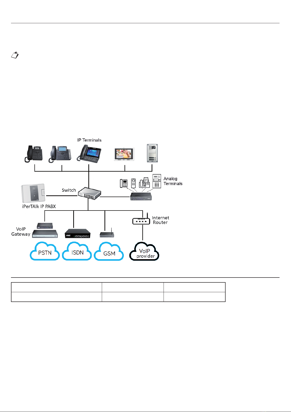
6. CONNECTION TO THE NETWORK.................................................................................................................. 9
7. MAXIMUM DISTANCES AND WIRE SECTIONS............................................................................................... 9
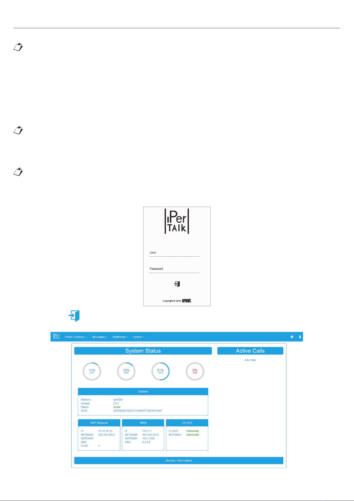
8. CONFIGURATION AND FIRST USE ............................................................................................................... 10
8.1 AUTOMATIC AND MANUAL CONFIGURATION OF USER TERMINALS ................................................ 13
9. ACCESS TO THE TELEPHONE NETWORK ................................................................................................... 13
9.1 MODELS REF. 1375/805 - 1375/810.................................................................................................. 13
9.2 MODEL REF. 1375/815....................................................................................................................... 14
10. TELEPHONE FUNCTIONS ............................................................................................................................. 14
10.1 DO NOT DISTURB .............................................................................................................................. 15
10.2 UNCONDITIONAL FORWARDING, FORWARD ON NO ANSWER AND ON BUSY
(INTERNAL/EXTERNAL)...................................................................................................................... 16
10.3 PUT ON HOLD/RECOVER CALL ........................................................................................................ 16
10.4 CALL PARKING................................................................................................................................... 16
10.5 TRANSFER WITH OFFER, BLIND, IN RINGING ................................................................................. 16
10.6 THREE-WAY CONFERENCE CALL ................................................................................................... 17
10.7 WAITING CALL NOTIFICATION.......................................................................................................... 17
10.8 INTERCOM.......................................................................................................................................... 17
10.9 CALL TO GROUPS OF EXTENSIONS, WITH SIMULTANEOUS OR SEQUENTIAL RINGING .......... 17
10.10 CALLING NUMBER OR NAME DISPLAY ........................................................................................... 18
10.11 INTERNAL/INBOUND CALL DISTINCTIVE RING ............................................................................... 18
10.12 MESSAGE WAITING INDICATOR (MWI)............................................................................................. 18
10.13 STATE OF EXTENSIONS (BLF)........................................................................................................... 18
10.14 PICK GROUP AND DIRECT PICK....................................................................................................... 18
10.15 POST SELECTION VIA DTMF............................................................................................................. 19
10.16 HOT-LINE............................................................................................................................................ 19
10.17 SELECTION OF LINE TRUNK FOR OUTBOUND CALLS ................................................................... 19
10.18 DISPLAY OF SPECIFIC OUTBOUND CALLING NUMBER................................................................. 20
10.19 OUTBOUND CALL RESTRICTION...................................................................................................... 20
10.20 COMPRESSED AND WIDEBAND CODEC MANAGEMENT................................................................ 20
11 SYSTEM FUNCTIONS .................................................................................................................................... 20
11.1 ALARM/APPOINTMENTS ................................................................................................................... 20
11.2 VIDEO CALL SUPPORT...................................................................................................................... 21
11.3 SUPPORT OF VOIP FAX DEVICES (SIP T.38) .................................................................................... 21
11.4 FAX2MAIL SERVICE ........................................................................................................................... 22
11.5 SENDING SMS ................................................................................................................................... 23
11.6 EXTERNAL IP VIDEO STATIONS........................................................................................................ 24
iPerTAlk IP-PBX Version: 2.1.4 or higher
The document contains INTERACTIVE LINKS for faster and more efcient consultation.
Interactive Links

3
DS1375-020C
11.6.1 Connection of 1375/821 – 1375/822 external IP video stations ............................................. 25
11.6.2 Conguration of 1375/821 – 1375/822 external IP video stations........................................... 26
11.6.2.1 External IP video stations keys pairing and advanced conguration................................... 27
11.6.3 Forwarding Call/Video call from external IP video station to phone / videophone................. 29
11.6.4 Forwarding Call/Video call from phone/videophone to external IP video station................... 29
11.6.5 Management of Video call to 1375/815 telephones............................................................... 29
11.6.6 Conversation timeout setting.................................................................................................. 29
11.6.7 Door opening command sending ........................................................................................... 30
11.6.7.1 Sending of door opening command during a conversation ................................................ 30
11.6.7.2 Sending the door opening command in Standby
(when not engaged in a conversation)................................................................................. 30
11.7 CALL MODULES 1375/823 ELEKTA AND 1375/824 ELEKTA STEEL................................................ 30
11.7.1 Connection of call modules 1375/823 – 1375/824................................................................ 31
11.7.2 Conguration of call modules 1375/823 – 1375/824.............................................................. 32
11.7.2.1 Call module advanced congurations................................................................................. 33
11.7.2.2 Phonebook conguration (administrator user only)............................................................ 34
11.7.2.3 Conguration of switchboard call (main telephone)............................................................ 34
11.7.3 Making a call/video call from call module to telephone/videophone or
video door phone 1375/825................................................................................................... 35
11.7.4 Making a call/video call from telephone/videophone to call module...................................... 35
11.7.5 Management of Video call to 1375/815 telephones............................................................... 35
11.7.6 Conversation timeout setting.................................................................................................. 35
11.7.7 Door opening command sending ........................................................................................... 35
11.7.7.1 Sending of door opening command during a conversation................................................. 36
11.7.7.2 Sending door opening command in standby (not during conversation)............................... 36
11.8 MAX IP VIDEO DOOR PHONE 1375/825............................................................................................ 36
11.8.1 Connection of IP video door phone 1375/825....................................................................... 36
11.8.2 Conguration of IP video door phone 1375/825..................................................................... 37
11.8.2.1 Advanced congurations of IP video door phone 1375/825............................................... 38
11.8.3 Conguration of switchboard call (main telephone)............................................................... 40
11.8.4 Making a call from video door phone to telephone or video door phone............................... 40
11.8.5 Making a call from telephone to video door phone................................................................ 40
11.9 AUTOMATIC ACTIVATION FROM IP VIDEO DOOR PHONE 1375/825 OR FROM
VIDEOPHONE 1375/815 ..................................................................................................................... 40
11.10 ACCESS CONTROL (ADMINISTRATOR USER ONLY)....................................................................... 40
11.11 CUSTOMIZATION OF RECEPTION MESSAGES AND WAITING MESSAGES................................... 41
11.12 PERSONAL AND SYSTEM DIRECTORY ............................................................................................ 42
11.13 INBOUND/MISSED/OUTBOUND CALL RECORD.............................................................................. 43
11.14 EXPORT OF CALL DATA .................................................................................................................... 44
11.15 USER AND EXTENSION STATUS CONFIGURATION ........................................................................ 44
11.16 REAL-TIME CONSULTATION OF THE STATE OF SYSTEM’S LINES AND EXTENSIONS ................ 46
11.17 DATE AND TIME AUTOMATIC UPDATE ............................................................................................ 47
11.18 RECORDING OF TELEPHONE CALLS ............................................................................................... 47
11.19 SETTING CALL FORWARDING TO SMARTPHONE/TABLET VIA CallMe APP .................................. 48
11.20 INTEGRATION WITH IPERCOM 2.0 SYSTEM.................................................................................... 51
11.20.1 IperCom Lines........................................................................................................................ 51
11.20.2 Simultaneous calls on IperCom trunks.................................................................................. 52
11.20.3 Creating an inbound routing rule........................................................................................... 52
11.20.4 Enabling the Ipercom Network.............................................................................................. 53

4DS1375-020C
12. SYSTEM CONFIGURATION ........................................................................................................................... 55
12.1 INBOUND ROUTING........................................................................................................................... 55
12.2 OUTBOUND ROUTING....................................................................................................................... 56
12.3 PROFILE CALENDAR ......................................................................................................................... 57
12.4 BLACKLIST ......................................................................................................................................... 57
12.5 APPLICATIONS................................................................................................................................... 57
12.5.1 Multi-company service (ITM)................................................................................................... 58
12.5.2 Voicemails (VMAIL / Consultation).......................................................................................... 61
12.5.3 Operator station (POA) installation.......................................................................................... 63
12.6 GROUP MANAGEMENT ..................................................................................................................... 64
12.7 SOFTWARE UPDATE.......................................................................................................................... 65
12.8 FIAS PROTOCOL INTEGRATION MODULE ....................................................................................... 66
12.9 ADVANCED CONFIGURATIONS ........................................................................................................ 66
12.9.1 Extensions............................................................................................................................... 66
12.9.1.1 Gateway conguration......................................................................................................... 67
12.9.1.2 Analogue user terminal support, IP/SIP, THIRD-PARTY software...................................... 67
12.9.2 Lines........................................................................................................................................ 70
12.9.2.1 Overow on line trunks........................................................................................................ 70
12.9.2.2 Trunk mapping ..................................................................................................................... 71
12.9.2.3 VOIP Lines ........................................................................................................................... 71
12.9.2.3.1 VOIP Lines for URMET gateway....................................................................................... 72
12.9.2.3.2 IPERCOM Lines (future implementation).......................................................................... 73
12.9.2.3.3 VOIP provider lines ........................................................................................................... 74
12.9.2.3.4 Trunk lines (VoIP Junction)................................................................................................ 74
12.9.3 Line trunks.............................................................................................................................. 75
12.9.4 System setting ........................................................................................................................ 76
12.9.4.1 System................................................................................................................................. 76
12.9.4.2 Network - Telephone network.............................................................................................. 77
12.9.4.3 Network - WAN .................................................................................................................... 77
12.9.4.4 Remote connections via VPN Tunnel................................................................................... 77
12.9.4.4.1 Remote ofces via VPN Tunnel......................................................................................... 78
12.9.4.4.2 Remote telephones via VPN Tunnel................................................................................. 78
12.9.4.5 Date and time....................................................................................................................... 79
12.9.4.6 Licenses ............................................................................................................................... 79
12.9.5 System maintenance............................................................................................................... 79
12.10 OPERATOR CONSOLE....................................................................................................................... 80
12.10.1 Internal call management...................................................................................................... 80
12.10.2 Inbound call management.................................................................................................... 80
12.10.3 Alarm clock........................................................................................................................... 80
12.11 CDR (CALL RECORD)......................................................................................................................... 81
12.12 BACKUP/RESTORE OF THE CONFIGURATION FROM WEB INTERFACE ....................................... 81
12.13 SPEED DIAL........................................................................................................................................ 82
12.14 EXTENSION MANAGEMENT .............................................................................................................. 82
12.15 EXTENSION REGISTRY...................................................................................................................... 83
13. SAFETY ......................................................................................................................................................... 84
13.1 REPLACING THE BATTERY ............................................................................................................... 84

5
DS1375-020C
1. GENERAL DESCRIPTION
iPerTAlk IP-PBX can be used to manage VoIP/SIP telephone installations by direct interconnection with remote
VoIP operators.
2. DESCRIPTION OF COMPONENTS
FRONT VIEW UPPER VIEW
3
2
1
4
5
6
1. Power LED
2. Status LED
3. Reboot and reset button
4. Disassembly screw cover (front cover)
5. USB connectors
6. LAN port
INTERNAL VIEW
7
9
8
7. Battery
8. Battery housing
9. Power connector

6DS1375-020C
3. INSTALLATION
For the rst installation of the device, proceed as follows:
1. Open ap (4) by making it slide outwards.
2. Undo the screw using a Phillips screwdriver and remove the front cover.
3. Fix the base to the wall with screws and wall anchors (provided in kit).

7
DS1375-020C
4. By exerting a slight pressure, insert the battery (7) in the battery housing (8), following the correct polarity.
5. Connect the power supply to the power connector (9). According to the position of the device, use the pre-cut
holes (A) on the right or on the left, arranged for passing through the power supply cable.
A
6. Close the previously removed front cover with the screw.

8DS1375-020C
4. DESCRIPTION OF LEDS, CONNECTORS AND BUTTONS
4.1 POWER LED (1)
LED colour Description
Green Device powered
LED off Device not powered
4.2 STATUS LED (2)
LED colour Description
Green xed System working with installed license
Red xed System not working
1 blue ash
1 green ash Internet connection is not available (no communication with Cloud Urmet)
3 red ashes
1 green ash System working with license not installed
3 red ashes
1 green ash
1 blue ash
System working with license not installed and connection to the Internet not
available (no communication with Cloud Urmet)
4.3 LAN PORT LED (6)
LED colour Description
Green ashing Connection to the LAN at 100Mbit/s
Orange ashing Connection to the LAN at 1Gbit/s
4.4 USB CONNECTORS (5) AND REBOOT AND RESET BUTTON (3)
Component Description
USB connectors 4 USB 2.0 ports for connecting of external USB storage devices or expansion units.
Reset and restart
button
Reboot the system: press the button until the WHITE LED lights up.
Restore default settings: hold the button pressed until the RED status LED lights up.
Release the button, switch power off and back on again.
5. PRELIMINARY CHECKS
Before establishing the network connections, perform the following checks to be able to use all iPerTAlk features
self-conguration. In particular, check that:
The company/PC network has a DHCP service.
Check that there is a free socket near the installation site.
The switch used in the system has at least one free Ethernet port.
Also check that an Internet connection adequate to support the number of simultaneous calls which are
needed is available.
Also check that an Internet connection is available adequate to support the number of simultaneous calls
which are needed. The following table shows the speed required to make good quality VoIP calls.
Number of concurrent calls Required bandwidth (upload & download)
185 kbps
2174 kbps
4358 kbps
8696 kbps
•
•
•
•
•

9
DS1375-020C
6. CONNECTION TO THE NETWORK
Follow the procedure below to make network connections.
Connect one end of the Ethernet cable to the LAN port on the switch and the other end to the LAN port (6) of
the device.
It is possible to use a switch already arranged in the network or install a new one (see Ref. 1039/44) to
make a new network. Where possible, the switch integrated into the Internet Router may be used.
Connect the power supply to the mains. The power LED (1) will turn GREEN.
The device will effectuate the software boot up procedure. At booting up, the status LED (2) of the device will
turn GREEN xed to indicate that the system is working and ready to be congured. If you do not have an
Internet connection, the status LED (2) will blink alternatively BLUE and GREEN to indicate the absence of
communication with the Urmet Cloud. System conguration is still possible in this condition.
In case the system cannot boot up correctly, refer to the table in the “DESCRIPTION OF LEDS, CONNECTORS AND
BUTTONS” chapter.
Below is an example of the connection diagram.
7. MAXIMUM DISTANCES AND WIRE SECTIONS
Type of connection Max. distance Min - max section
LAN 100 m (*) CAT5e (#)
(*) The maximum permissible distance is that dened by IEEE 802.3 for Fast Ethernet networks
(100 Mb/s) with UTP CAT5 connections, which establishes that the maximum distance between two Ethernet
devices connected to each other must be 100 m.
(#) To ensure operation of the device at maximum distances, the wire must be in Category 5e and the section of
the twisted pairs must be AWG24.
The maximum resistance of the individual wires must not exceed 10ohm/100m. The connection between the door
phone and POE switch must be ensured by a single cable without any extra patch cords.
The cable must be up to the following standards:
- EIA/TIA 568-B.2 or EIA/TIA 568-C.2
- EN50288 3-1
- IEC 61156-5
1.
2.
3.
WARNING!
You can only make audio calls to
videophone terminals.
WARNING! You can only make
audio calls from a videophone to a
video door phone Ref. 1375/825.
The administrator can customise
the congurations of each extension
according to needs, from the page
“Extensions and Lines Status”.
It is possible to activate the page
of the iPerTAlk User interface from
which it is possible to extract the
tags of the calls managed by the
iPerTAlk system in a determined
period, according to selection
lters.

10 DS1375-020C
8. CONFIGURATION AND FIRST USE
A PC (Windows, Linux or Mac) running a browser is needed to access iPerTAlk conguration.
Use of the following browsers is recommended to ensure maximum compatibility:
Internet Explorer 11.x or higher;
Mozilla Firefox 50.x or higher;
Chrome 60.x or higher.
Follow the instructions below to complete the conguration.
1. Connect the PC to the network where iPerTAlk is connected.
2. iPerTAlk, in default conguration is congured to receive the IP address from the DHCP Server of the IP
network which hosts it. However, if the DHCP server is not available, after 150 seconds iPerTAlk automatically
assigns the following IP address 192.168.56.245 to itself, in order to allow reachability in the network.
If you have a PC capable of accessing the VLAN (default 5 for iPerTAlk), it is always possible to access the
iPerTAlk conguration interface at https://10.10.10.10
3. Start the browser on your PC and enter the iPerTAlk address in the address bar to access the conguration
web page.
Accept the security certicate following the procedure suggested by the Web browser in use.
4. Login using the default Username and Password:
User: installer
Password: 0000
5. Press the icon to access the conguration page.
6. The main page will appear when logging on automatically.
•
•
•

11
DS1375-020C
7. On the top menu, press System and select the Wizard to proceed with the guided and simplied conguration
of all main parameters.
The following table lists the congurable features. Refer to the installation and conguration booklet for more
information.
Step Wizard step Description
1 License Can be used to integrate the installed basic license, with additional licenses
by means of the license les.
2System This can be used to congure/check the VLAN network parameters.
3VoIP Phones Can be used to dene the extensions of the system.
4VoIP interfaces+
Extensions Can be used to congure the extension gateways.
5VoIP L.U. / ISDN / GSM
interfaces
This can be used to automatically acquire the gateways of analogue line, ISDN,
Urmet and GSM.
6 Provider VoIP This can be used to congure the VoIP lines to gateway provider for traditional
third-party lines and third-party PBX.
7 FAX This can be used to activate fax channels in iPerTAlk.
8 Video Entry Devices This can be used to congure IP/SIP door units and monitors.
9Interactive Voice
Response
This can be used to congure the pre-installed automatic answering service (ITM)
for incoming calls.
10 Call routing This can be used to congure incoming and outgoing routing rules.
8. To load an additional license, follow the next step, otherwise go directly to step 11.
If the license is not installed, the status LED alternates xed GREEN and three RED ashes.
La procedura di Reset non cancella la licenza nel caso sia stata installata in precedenza.
9. Proceed by loading the license from the PC by selecting the le called “UUID iPerTAlk.lic” in the disc and
pressing “Load”.

12 DS1375-020C
10. Wait for the system to boot and login again. Open the Wizard page from the System menu.
11. To change the subnet that iPerTAlk self-assigned, select step 2 of the Wizard.
12. Select step 3 of the Wizard “VoIP telephones”.
13. Connect the telephone devices to the network where iPerTAlk is connected via the LAN network cable
supplied and wait for them to appear on the “VoIP Phones” page.
If the network where iPerTAlk is installed does not have a DHCP server, manually force the VLAN (5 default
iPerTAlk) of the IP Terminals so that they can receive an address from iPerTAlk and then be detected.

13
DS1375-020C
14. Select the Terminal Acquisition method (Automatic Conguration) you want to use for the conguration:
– acquisition enabled: it detects and congures devices 1375/805 /810 /815 fully automatically, by assigning
the extension number progressively (starting from 90201) as the devices are detected in the network.
– acquisition disabled: it detects devices 1375/805 /810 /815. The detected devices are listed in the table
below, with relevant MAC Address, assigned IP address and Urmet Item no.
Press on the “Add” link to acquire the device and assign to it the rst extension available (starting from
90201).
Press on the “Blacklist” link to keep the device in the list of the acquired devices without entering it in the
system.
15. The Terminal Acquisition procedure sends the conguration parameters to the device and, if necessary,
updates the rmware. At the end of the procedure, the device that received an extension number remains
linked to the system until it is deleted from iPerTAlk and then reset to the factory default values.
8.1 AUTOMATIC AND MANUAL CONFIGURATION OF USER TERMINALS
Automatic provisioning is provided for only for Urmet terminal Ref. 1375/805, 1375/810 and 1375/815, Urmet IP
Outdoor Stations of the iPerTAlk range (1375/821, /822).
An available DHCP server (WAN or ADSL router) is required in the network to use the automatic conguration
functions of the system.
In the case that there is not a DHCP server, the installer has to manually congure the terminals in order
to perform the connection to the iPerTAlk VLAN (default TAG 5). Refer to the chapter “ACCESS TO THE
TELEPHONE NETWORK” or to the manuals of the devices to activate the VLAN on the correct network
port.
Should the device be not able to manage the VLANs, it will be necessary to use a switch that allows this
function (IEEE 802.1Q).
9.
ACCESS TO THE TELEPHONE NETWORK
To access the web conguration interface of iPerTAlk and the terminals, once they are active on the iPerTAlk
VLAN, it will also be necessary to congure the PC with the same VLAN TAG.
9.1 MODELS REF. 1375/805 - 1375/810
Proceed as follows to congure VLAN mode via the telephone user interface:
1. Press Menu → Settings → Advanced Settings (default password: Admin) → Network → VLAN Port.
2. Select the LAN PORT, select “Enabled” to activate the function of parameter 1.
3. Indicate the selected VLAN (default 5 for iPerTAlk) to parameter 2.
4. Leave parameter 3 set to 0.

14 DS1375-020C
5. Press SAVE. The device will reboot, if iPerTAlk is connected to the same physical network, on the same
switch the device will receive an IP address from the DHCP server on the iPerTAlk system on the telephone
network, i.e. 10.10.10.x
9.2 MODEL REF. 1375/815
To congure VLAN mode through the telephone’s user interface, follow the procedure below:
1. Access the device settings.
2. Select the item “Other” and access VLAN parameter.
3. Check the box of the item “LAN Port Settings” and enter the number of the VLAN (5 by default for iPerTAlk)
in the parameter “LAN Port ID”. Press OK to conrm.
4. The change is immediately implemented and the device receives an IP address from the DHCP server of
iPerTAlk on the telephone network, namely 10.10.10.x.
5. Restart the terminal to start the automatic conguration.
If this function cannot be activated in the PC, use the network port called “PC” of one of the Urmet VoIP telephones
connected in the network. Follow the steps below:
1. Select the following menu items:
Menu → Settings → Advanced settings (default Password: admin) → Network → VLAN Port
2. Select the PC PORT and:
a) at point 1 activate VLAN TAG function;
b) at point 2 indicate the chosen VLAN (5 by default for iPerTAlk);
c) leave the Priority parameter at 0.
3. Then connect the PC to the “PC” port of the Urmet telephone and set in the PC a static IP in the
iPerTAlk subnetwork (e.g. 10.10.10.201 netmask 255.255.255.0) it will be possible to access iPerTAlk
and all the devices in VLAN.
10. TELEPHONE FUNCTIONS
The telephone functions on extensions described in the following paragraph can be congured/enabled/disabled
through the Web interface of iPerTAlk or through the settings on the terminal.
From the menu Telephone functions access the page State of Extensions and Lines and select Congure on
the concerned extension.

15
DS1375-020C
The conguration page can be accessed in this way.
10.1 DO NOT DISTURB
This service allows you to activate the “do not disturb” function to block (until the opposite command is sent) the
incoming calls to your terminal.
Your extension will be busy for internal and external callers.
The terminal can still perform outbound calls.
The busy state will be kept until it is disabled.
To align the service, press the DND key on the terminal or use the web interface: select Telephone Functions
and press State of Extensions and Lines, select the required extension and press Congure, enable the “Do
not disturb” function.
The function activated on the terminal will be replicated on the iPerTAlk conguration displayed on the web
page.

16 DS1375-020C
10.2 UNCONDITIONAL FORWARDING, FORWARD ON NO ANSWER AND ON BUSY
(INTERNAL/EXTERNAL)
iPerTAlk allows forwarding all the calls addressed to an extension with three types of forwarding:
unconditional forwarding performed always for any call;
forward on no answer timeout (if the incoming call is not managed);
forward on busy when the user is engaged in a call or has activated the “do not disturb” function.
Forwarding types can be set in three ways:
by setting them on the terminal;
by an activation/deactivation code sent with a call to iPerTAlk;
Through conguration via web page in the iPerTAlk (my Talk) interface at the chapter “USERS AND EXTENSIONS
STATUS CONFIGURATION”.
For the activation on the terminal, refer to the relevant user’s manual.
For the activation through code, just enter the codes indicated in the table below from the terminal concerning
the forwarding.
*20*XXX Activate the “forward all”
function
Activate the “forward all” function for your extension to number
XXX
*22*XXX Activate the “forward on busy”
function
Activate the “forward on busy” function for your extension to number
XXX
*21*XXX Activate the “forward on
no answer” function
Activate the “forward on no answer” function for your extension to
number XXX
*29# Disable all forwarding
For the activation through the web page, refer to the paragraph explaining functions and use of MyTalks.
10.3 PUT ON HOLD/RECOVER CALL
During a telephone call, it is possible to put the interlocutor on hold. Activate the Hold command (only during a
call) to interrupt the call.
The interlocutor will hear the music on hold congured in iPerTalk until the person using this service will recover
the call (by pressing a dedicated key).
If the caller/receiver who puts the interlocutor on hold hangs up the phone, iPerTAlk recalls the user (who
erroneously left the call on hold) to resume the call.
10.4 CALL PARKING
During the call it is possible to put the interlocutor on hold and park the call in a parking orbit by means of a
transfer to number *30*X where X is the chosen parking orbit (from 1 to 9).
Once the call has been parked, it is possible to hang up the phone. Then, by means of *33*X command it will be
possible to “resume the call”, namely to restart it, either from the same extension or from another one.
Practically, setting a call in the “parking orbit” allows putting it on hold, freeing the terminal from its
management.
To park a call (for example in orbit 1):
answer the call;
press the TRASF key;
digit *30*1 and press TRASF.
To resume a call (for example parked in orbit 1):
dial the code *33*1 on the terminal and press OK.
For devices 1375/815, after entering the code of the orbit, choose “Unconditional” since the TRASF
button is not available , but the user is asked to choose the type of transfer.
10.5 TRANSFER WITH OFFER, BLIND, IN RINGING
The terminal that makes or receives a call can put the call on hold and then transfer it to another terminal
registered in the system.
—
—
—
—
—
—
—
—
—
—

17
DS1375-020C
The transfers are of three types:
(1) with offer, when a call is transferred after having “announced” to the third party involved that the user is about
to transfer a call previously received or made;
(2) blind, when a call is transferred without checking if the third party is available to receive the call (engaged in
another call, not reachable, busy);
(3) in ringing, if during the transfer, the person who performs it hangs up or completes it by pressing TRASF as
soon as he/she hears the ringing signal of the third party.
To perform a transfer with offer (1): start the transfer with TRASF key, dial the number to which you want to
transfer the call, wait for the answer and press TRASF key again or hang up.
To perform a blind transfer (2): start the transfer with TRASF key, dial the transfer destination number and press
TRASF key again. The call will be ended and transferred.
To perform a transfer in ringing (3): start the transfer with TRASF key, dial the transfer destination number, wait
for the ring signal and press TRASF again or hang up.
10.6 THREE-WAY CONFERENCE CALL
iPerTAlk allows three-way conference calls through the terminals that feature this function. To use this function,
just put on hold the rst call made from the terminal, make another call and activate the function once the call with
the second interlocutor has started.
The telephone terminal will connect the rst call with the second one, allowing a full duplex call for the three
parties so that all can participate in it and listen.
To end the conference call, just end your call freeing the interlocutors.
10.7 WAITING CALL NOTIFICATION
This function allows for a visual and audio notication of the presence of a call waiting while a terminal is engaged
in a call.
This function is disabled by default in the iPerTAlk system; the function can be enabled by means of the conguration
web interface in the extension settings by selecting the “Waiting call” function.
During a call, the terminal can receive many call waiting notications at a time.
The user engaged in the call can decide whether to put the current call on hold and answer the new one or end
the current call and then manage the second one, which has remained active.
10.8 INTERCOM
iPerTAlk supports the Intercom function if the terminals are enabled. To enable this service, congure the
INTERCOM function on a programmable key by entering the extension number of the counterparty.
Press the INTERCOM key to make the device call the counterparty, which directly starts the call.
This service is useful in case of manager/secretary scenarios when a button for direct communication with the
secretary is required in the manager’s terminal, so that he/she does not have to dial the number and the secretary
can accept the call automatically without having to touch the receiver.
10.9
CALL TO GROUPS OF EXTENSIONS, WITH SIMULTANEOUS OR SEQUENTIAL RINGING
iPerTAlk supports the creation of groups of extensions. An extension number in the system is assigned to the
group.

18 DS1375-020C
There are two modes to manage a call to the extension of a group:
1 - Sequential ringing mode: the free extensions in the group ring sequentially, starting from the group’s
extension that has not answered a call for the longest amount of time; the passage from one extension to the
subsequent one is equal to the duration of the time of no answer.
2 - Simultaneous ringing mode: all the group’s free extensions ring simultaneously; when one extension answers
the call, the ringing stops on all the other group’s extensions.
10.10 CALLING NUMBER OR NAME DISPLAY
All the devices connected to iPerTAlk and equipped with a display can show the calling number. This always
happens in case of calls between extensions.
As regards calls from external lines, this service is available if the termination gateway (analogue, ISDN, GSM or
Voip provider) can recognise and send the number of the external caller.
If the calling number is in the directory, the corresponding name will be shown together with the number.
10.11 INTERNAL/INBOUND CALL DISTINCTIVE RING
iPerTAlk communicates to IP devices the type of ring to be emitted, which can be different for internal and
inbound calls (namely coming from lines, either traditional, voip or of inter-site type).
These two rings are the same for all internal and inbound calls and are valid for all the extensions in the system
that enable this service.
This service has to be congured in the page dedicated to terminal congurations, in the advanced section.
If the service is disabled, users can congure their own device with one of the ring tones available in the terminal
and the tone is no longer differentiated based on the origin of the call.
The parameter is available in the conguration phase for each extension. For Urmet devices it is available in
the basic setting parameters of the terminal. For general devices (SIP Extension) it is available in the Advanced
Conguration parameters.
10.12 MESSAGE WAITING INDICATOR (MWI)
The MWI (Message Waiting Indicator) service allows receiving a notication when messages are present in the
voicemail. The indicator (if available) lights up to warn that there are new messages in the voicemail and by
pressing the relevant key a call is made to the automatic answering machine dedicated to the consultation of the
voicemail’s messages.
To activate the MWI function in a terminal that supports it, enable the subscription to the service. Refer to the
device’s installation manual.
For example, in the devices 1375/805, 1375/810 and 1375/815, access the device’s web interface: Advanced →
User → “Subscription” section: Enable.
The iPerTAlk system congures such service automatically for the above mentioned terminals.
10.13 STATE OF EXTENSIONS (BLF)
iPerTAlk supports the notication of the state of extensions through the BLF service ( Busy Lamp Field) for the
models equipped with extension keys (1375/810 and 1375/815).
The terminal, properly congured for this function, indicates the state of the monitored extension.
Press the corresponding key to:
1 - call the extension associated with the key, when the key indicates its state as free (light blue);
2 - answer the call addressed to the extension associated with the key (PICK or answer for absent extension),
when the key indicates the ring state (ashing red); such service is available only for Urmet terminals, and is
congured by means of the relevant conguration interface (see the device’s manual).
10.14 PICK GROUP AND DIRECT PICK
iPerTAlk supports the direct pick function (answer for absent extension) of a call addressed to an extension or to
a group of extensions.
This service allows answering a call addressed to an extension, (or a group of extensions) while it is ringing.

19
DS1375-020C
The pick function can be applied in two modes:
pick group: it allows each one of the extensions belonging to the same “pick group” to answer a call addressed
to another extension that is not answering (it is ringing). This mode requires the conguration of the “pick
group” parameter (Administrator User only) on each one of the extensions for which this function is to be
enabled, with the same numerical value.
iPerTAlk allows setting up to 10 “pick groups”.
The user performs the command by pressing the PICK key in the terminal or by lifting the receiver and dialling
the code *35*.
direct pick: it allows any extensions of a system to answer a call addressed to another extension, that is not
answering (it is ringing).
The user performs the command by pressing the BLF key of his/her own terminal associated with the extension
to be intercepted (when it ashes in red) or by lifting the receiver and dialling the code *37*XXX where XXX are
the three digits of the extension that is ringing.
10.15 POST SELECTION VIA DTMF
iPerTAlk supports the post selection function, namely it allows sending DTMF digits during the calling phase. It
is therefore possible, for example when contacting a service, that it requests to press digits to access telephone
menus (press 1 for..., press 2 for...), dial the requested digits.
Post selection via DTMF is possible only after the call has started with the counterparty and not during the call
activation phase.
10.16 HOT-LINE
iPerTAlk supports the Hot-line function if the terminals connected to it support such function.
The terminal, properly congured, automatically generates a call to a pre-set number, releasing the receiver or
activating the hands-free mode.
In case of Urmet terminals (IP telephones or gateway for analogue telephones), this function can be set from the
telephone menu or by means of the web interface:
It is also possible to set a start time from 0 to 5 seconds to prevent, for example, undesired automatic calls.
10.17 SELECTION OF LINE TRUNK FOR OUTBOUND CALLS
If iPerTAlk manages several lines grouped in different trunks, through line gateways or VoIP operators, iPerTAlk
allows selecting the trunk to be used for outbound calls, when a different line trunk from the extension’s default
one is to be used.
A code #X, with X ranging from 0 to 9, is associated to every line trunk in the system. By dialling this code just
before the called number, it is possible to use a specic line trunk.
The programming of these codes and the associated line bundle is a conguration programmed in system by the
administrator / installer user.
—
—

20 DS1375-020C
10.18 DISPLAY OF SPECIFIC OUTBOUND CALLING NUMBER
If iPerTAlk manages several lines with different associated numbers, through line gateways or VoIP operators, it
allows conguring the numbers that are displayed for outbound calls.
The programming of such codes and the relevant associated line trunk, is a conguration programmed in
the system by the administrator/installer.
Editing the caller’s number in case of a VoIP provider usually causes a malfunction of the line since the
provider identies the user based on the number that is displayed.
10.19 OUTBOUND CALL RESTRICTION
iPerTAlk allows conguring public numbers that can be called both for specic extensions and at a system
level.
any outbound call;
international calls;
calls to special area codes (according to customised rules, e.g.: those that start with 3, if you want to block all
the calls to mobile numbers).
The conguration of call restrictions is a programming available only to Administrator users.
10.20 COMPRESSED AND WIDEBAND CODEC MANAGEMENT
iPerTAlk allows conguring, on a single extension and single line trunk level, audio/video codecs available for the
extension, for inbound and outbound calls.
11 SYSTEM FUNCTIONS
11.1 ALARM/APPOINTMENTS
iPerTAlk features the Alarm/Appointments function, namely the possibility to generate an automatic call, with
customised message, that can be activated for a specic date/time and that can be repeated if necessary.
The destination of the call can be an extension or a public network number (in this case, the destination number
is to be entered including any area code for engaging the line).
This function can be set through the menu Multimedia → Appointments.
To set an Alarm/Appointment press the key and enter the required values in the displayed elds:
Target: the number to be automatically called (internal or external number).
Date: the date on which the service is to be activated.
Time: the time at which the service is to be activated.
Repetitions: None (single call), Every day or select the days of the week on which the service is to be
activated.
Conrm with the key
.
If parameters are correct, the alarm/appointment will be indicated in the list.
Once the desired music has been loaded, select it in the drop-down menu under “Alarm Music”.
The alarm setting can be modied with key or the set alarm can be removed by means of the key
.
—
—
—
—
—
—
—
Other manuals for IPerTalk 1375/10
2
This manual suits for next models
2
Table of contents
Other urmet domus Conference System manuals