USSC Logwood C226 User manual

CAUTION!CAUTION!
CAUTION!CAUTION!
CAUTION!
Read All Instructions Care-Read All Instructions Care-
Read All Instructions Care-
fully Before Starting The In-fully Before Starting The In-
fully Before Starting The In-
stallation or Operating Thisstallation or Operating This
stallation or Operating This
Heater.Heater.
Heater.Heater.
Heater. DO NOT USE THIS HEATERDO NOT USE THIS HEATER
DO NOT USE THIS HEATERDO NOT USE THIS HEATER
DO NOT USE THIS HEATER
IN A MOBILE HOME OR TRAILERIN A MOBILE HOME OR TRAILER
IN A MOBILE HOME OR TRAILER
SAVE THIS MANUAL FOR FUTURE REFERENCESAVE THIS MANUAL FOR FUTURE REFERENCE
SAVE THIS MANUAL FOR FUTURE REFERENCE
THISMANUALWILLHELPYOUTOOBTAINEFFICIENT,DEPENDABLESERVICEFROMTHEHEATER,ANDENABLETHISMANUALWILLHELPYOUTOOBTAINEFFICIENT,DEPENDABLESERVICEFROMTHEHEATER,ANDENABLE
THISMANUALWILLHELPYOUTOOBTAINEFFICIENT,DEPENDABLESERVICEFROMTHEHEATER,ANDENABLE
YOU TO ORDER REPAIR PARTS CORRECTLY. KEEP IN A SAFE PLACE FOR FUTURE REFERENCE.YOU TO ORDER REPAIR PARTS CORRECTLY. KEEP IN A SAFE PLACE FOR FUTURE REFERENCE.
YOU TO ORDER REPAIR PARTS CORRECTLY. KEEP IN A SAFE PLACE FOR FUTURE REFERENCE.
UNITED STATES STOVE COMPANYUNITED STATES STOVE COMPANY
UNITED STATES STOVE COMPANY
227 Industrial Park Road
P.O. Box 151
South Pittsburg, TN 37380
(423) 837-2100
C
O
M
P
A
N
Y
U
N
I
T
E
D
S
T
A
T
E
S
S
T
O
V
E
C
S
S
U
Owners Manual
Logwood C226Logwood C226
Logwood C226
851475A
TESTED TOTESTED TO
TESTED TOTESTED TO
TESTED TO
UL 1482UL 1482
UL 1482UL 1482
UL 1482
&&
&&
&
CAN/ULC S627CAN/ULC S627
CAN/ULC S627

CONGRACONGRA
CONGRACONGRA
CONGRATULATULA
TULATULA
TULATIONS!TIONS!
TIONS!TIONS!
TIONS!
You've purchased a heater from North America's oldest manufacturer of wood burning
products.
By heating with wood you're helping to CONSERVE ENERGY!
Wood is our only Renewable Energy Resource. Please do your part to preserve our wood
supply. Plant at least one tree each year. Future generations will thank you.
TT
TT
Tools and Materials Neededools and Materials Needed
ools and Materials Neededools and Materials Needed
ools and Materials Needed
TOOLSTOOLS
TOOLSTOOLS
TOOLS
Pencil
6 Foot Folding Rule or Tape Measure
Tin Snips
Drill, Hand or Electric
Drill Bit 1/8" Dia. (For Sheet Metal Screws)
Adjustable Wrench
Screw Driver (Blade-Type)
Gloves
Safety Glasses
MATERIALSMATERIALS
MATERIALSMATERIALS
MATERIALS
6" Elbow, Collar and Thimble; As Required
(24 gauge min.)
1/2" Sheet Metal Screws (No. 10A x 1/2")
6" Diameter, 24 gauge, black or blued steel
Underwriters Laboratories (UL,ULC) Listed
Residential Type HT (2100°F) Chimney or use a
Masonry Chimney in good repair.
Floor Protector Material (R value = 2.0); Size and
Installation as specified on Page 4
Furnace Cement (Manufacturer Recommends:
Rutland Black Code 78 or Equivalent)
6" Barometric Draft Regulator (DR-6)
22
22
2
HEATER DIMENSIONSHEATER DIMENSIONS
HEATER DIMENSIONS
FIG. 1FIG. 1
FIG. 1FIG. 1
FIG. 1
33"
4-5/8"
FLOOR PROTECTOR
11-3/8"
18-1/2"
26-1/2"
8"
23"23"
23"23"
23"

33
33
3
Safety RulesSafety Rules
Safety Rules
SAFETY NOTICE:SAFETY NOTICE:
SAFETY NOTICE: If this heater is not properly installed a house fire may result. For your safety, follow the
installation directions. Contact local building or fire officials about restrictions and installation inspection
requirements in your area.
Read these rules and the instructions carefully.
Check with local codes. The installation comply
withtheirrulings.Observecloselytheclearances
to combustibles (page 4).
Do not install this heater in a mobile home or
trailer.
Alwaysconnectthisheatertoachimneyandvent
to the outside. Never vent to another room or
inside a building.
Do not connect a wood burning heater to a Type
B gas vent. This is not safe and is prohibited by
the National Fire Protection Association Code.
This heater requires approved masonry or UL,
ULC Listed Residential Type and Building Heat-
ingApplianceChimney.Usea6"diameterchim-
ney or larger, that is high enough to give a good
draft.
Be sure that your chimney is safely constructed
and in good repair. Have the chimney inspected
by the Fire Department or a qualified inspector.
Your insurance company may be able to recom-
mend a qualified inspector.
Inspect chimney connector and chimney twice
monthly during the heating season for any de-
posit of creosote or soot which must be removed
(see Chimney Maintenance, page 9).
Provideairforcombustionfromoutsidethehouse
into the room where the heater is located. If the
intakeisnotinthe sameroom,airmusthave free
access in to the room.
Toprevent injury,do notallow anyoneto usethis
heater who is unfamiliar with the correct opera-
tion of the heater.
1.
2.
3.
4.
5.
6.
7.
8.
9.
**
10.
11.
12.
13.
14.
For further information on using your heater
safely, obtain a copy of the National Fire Pro-
tection Association (NFPA) publication "Using
Coal and Wood Stoves Safely" NFPA No. HS-
10-1978. The address of the NFPA is
Batterymarch Park, MA 02269.
For more information on a Canadian Installa-
tion, obtain a copy of CAN/CSA - B365 - M91
InstallationCode for Solid-Fuel-Burning Appli-
ances and Equipment.
Disposal of Ashes- Place ashes in a metal
containerwithatightfittinglid.Keeptheclosed
containerona non-combustiblefloor or onthe
ground, well away from all combustible mate-
rials. Keep the ashes in the closed container
until all cinders have thoroughly cooled. The
ashesmaybeburiedinthegroundorpickedup
by a refuse collector.
CAUTION- The special paints used on your
heatermaygiveoffsomesmokewhiletheyare
curingduringthefirstfewfires.Buildsmallfires
at first.
CARING FOR PAINTED PARTS- This heater
hasa paintedjacket, whichis durablebut itwill
not stand rough handling or abuse. When
installing your heater, use care in handling.
Clean with soap and warm water when heater
is not hot. DO NOT use any acids or scouring
soap, as these wear and dull the finish. PAINT
DISCOLORATION WILL OCCUR IF THE
HEATER IS OVERFIRED. FOLLOW OPER-
ATING INSTRUCTIONS CAREFULLY.
All persons, especially children, should be
alerted to hazards from high surface tempera-
tures and kept away while in operation. Small
children should not be left unsupervised when
in the room with the heater.
Keep the area adjacent to the heater free from
all combustible materials, gasoline, and other
flammable vapors.
CAUTION! Do not touch the heater until it has cooled.CAUTION! Do not touch the heater until it has cooled.
CAUTION! Do not touch the heater until it has cooled.
NOTE:NOTE:
NOTE:NOTE:
NOTE:
FOR YOUR SAFETY, WE RECOMMEND INSTALLING SMOKE DETECTORS IN YOUR HOME IF NOTFOR YOUR SAFETY, WE RECOMMEND INSTALLING SMOKE DETECTORS IN YOUR HOME IF NOT
FOR YOUR SAFETY, WE RECOMMEND INSTALLING SMOKE DETECTORS IN YOUR HOME IF NOT
ALREADY INSTALLED.ALREADY INSTALLED.
ALREADY INSTALLED.

44
44
4
Place the heater on solid masonry or solid concrete. When
the heater is used on a combustible floor, use an Underwrit-
ers Listed floor protector. The floor protector must comply
with UL Standards (USA) and CAN/ULC (Canada). The
base should extend at least 16" beyond the door side of the
heater and should extend under the flue pipe if it is elbowed
towards a wall. (Fig. 5).
Uncrateand/or unpackthe heater,removing allpack-
ing material, being careful not to dispose of the Parts
Bag.
Open the front feed door and remove the parts from
insidethestove.Youshouldfindthefollowing:Hearth
Plate(1); Solid Damper(1); Lids (2); PivotingTop (1);
Lid Support (1); Parts Package (1) containing nuts,
bolts,doorhandle,door latchandsecuringhardware;
Legs (4); Cast Iron Collar (1); Cast Iron Damper (1);
Baffle Assembly (1); Lid Lifter (1).
Placecardboard or other soft material adjacent to the
stove and carefully turn the stove onto its top side
(bottom facing up).
Attachhearthplatetothefrontofthestoveinitsproper
location.
Attachbothrearandfrontlegstothestove.Tightenthe
nuts and bolts securely. The stove may now be
CAREFULLY turned over to stand on it four legs.
Attachthe baffle assemblyand flue collar tothe stove
by inserting the baffle studs through the two holes
locatedonthetopoftherearofthestove;placetheflue
collarover the studs and mount using the proper nuts
and washers. Place lid support and lid in position on
pivotingtop. Place theslide damper in positionon the
top of the hearth plate and under the feed door, and
secure with screw in slot.
After consulting the installation instructions for mini-
mum clearances to combustibles, locate your floor
protectoraccordingly and carefully place the stove in
your selected location. Install stove pipe, elbows and
thimble as necessary, utilizing either a recently
cleaned and inspected masonry chimney (properly
lined) or a UL/ULC Listed chimney. Insure that the
damper provided is installed in the flue collar.
Again, check the following illustrations and be sure
you have the clearances shown from the heater and
the connector pipe to combustible surfaces. If you
have a solid brick or stone wall behind your heater,
youmayplaceyourheaterascloseasyouwishtothe
wall. However, if the wall is only faced with brick or
stone, consider it a combustible wall.
If your chimney drafts excessively, purchase and use
a Barometric Draft Regulator (DR6 available from
factory).
The chimney connection should be as short as pos-
sible, and the heater must have its own flue. Do not
connect this unit to a chimney flue serving other
appliances.
Use three sheet metal screws in each stove pipe and
or elbow joint to firmly hold the pipe together.
Do not install this heater in a mobile home or trailer.
Check your local building and insurance codes. The
installation must comply with their rulings.
1.
2.
3.
4.
5.
6.
7.
8.
9.
10.
11.
12.
14.
InstallationInstallation
Installation
CAUTION!CAUTION!
CAUTION!CAUTION!
CAUTION!
KEEP FURNISHINGS AND OTHERKEEP FURNISHINGS AND OTHER
KEEP FURNISHINGS AND OTHER
COMBUSTIBLE MATERIALSCOMBUSTIBLE MATERIALS
COMBUSTIBLE MATERIALS
AWAY FROM THE HEATER.AWAY FROM THE HEATER.
AWAY FROM THE HEATER.
MINIMUM CLEARANCEMINIMUM CLEARANCE
MINIMUM CLEARANCE
TO COMBUSTIBLE WALLSTO COMBUSTIBLE WALLS
TO COMBUSTIBLE WALLS
US , CANADAUS , CANADA
US , CANADA
FLOOR
PROTECTOR FLOOR
PROTECTOR
FIG. 2FIG. 2
FIG. 2FIG. 2
FIG. 2
(60" MIN.)
18"
FIG. 3FIG. 3
FIG. 3FIG. 3
FIG. 3
34"
865mm 26"
660mm
28"
712mm
28"
712mm 20"
508mm
37-1/2"
953mm
458mm
FLOOR
PROTECTOR
BACKWALL
DASHEDLINES
SHOW STRAIGHT
OUT CHIMNEY
CONNECTOR
28"
60"
34"
865mm 26"
660mm
NON-COMBUSTIBLE
CONSTRUCTION IN
ACCORDANCE WITH
NFPA 211 or CAN/CSA
B365-M91
HEATER/FLOOR PROTECTOR LOCATIONHEATER/FLOOR PROTECTOR LOCATION
HEATER/FLOOR PROTECTOR LOCATION
(Dimensions are required for
non-protected surfaces
.
See chart for dimensions for
protected surfaces
.)
FIG. 2FIG. 2
FIG. 2FIG. 2
FIG. 2
FIG. 3FIG. 3
FIG. 3FIG. 3
FIG. 3
Protected Surfaces (NFPA 211)
Parallel Corner
Side Rear
12-inches 12-inches 12-inches
305-mm 305-mm 305-mm
FIG. 4FIG. 4
FIG. 4FIG. 4
FIG. 4
6"
153mm
6"
153mm
6"
153mm
16"
407mm
28-3/4"
730mm

WRONGWRONG
WRONGWRONG
WRONG
RIGHTRIGHT
RIGHTRIGHT
RIGHT
55
55
5
Operation of the HeaterOperation of the Heater
Operation of the Heater
1.
2.
3.
4.
5.
6.
7.
8.
FIG. 6FIG. 6
FIG. 6FIG. 6
FIG. 6
FIG. 5FIG. 5
FIG. 5FIG. 5
FIG. 5
ELBOW
COLLAR
THIMBLE
PIPE REDUCER
FLOOR PROTECTOR
FLOOR PROTECTOR
3 FT. MIN.
2 FT. MIN
10 FT.
CHIMNEYCAP MANDATORY
11 FT. MINIMUM
FIG. 7FIG. 7
FIG. 7FIG. 7
FIG. 7
WRONGWRONG
WRONGWRONG
WRONG
FLUE CONNECTION-NON-COMBUSTIBLE WALL
PIPE
NON-COMBUSTIBLEWALL
PIPE
BAROMETRIC
DRAFT REGULATOR
BAROMETRIC
DRAFT REGULATOR
PIPE
NON-COMBUSTIBLE
CONSTRUCTIONIN
ACCORDANCEWITH
NFPA211(USA)
orCAN/
CSA-B365-M91
BE SURE TO PUT A LAYER OF SAND OR FIREBRICKBE SURE TO PUT A LAYER OF SAND OR FIREBRICK
BE SURE TO PUT A LAYER OF SAND OR FIREBRICK
APPROXIMATELY 1 1/2" THICK IN THE BOTTOM OF THEAPPROXIMATELY 1 1/2" THICK IN THE BOTTOM OF THE
APPROXIMATELY 1 1/2" THICK IN THE BOTTOM OF THE
STOVE BEFORE STARTING FIRE.STOVE BEFORE STARTING FIRE.
STOVE BEFORE STARTING FIRE.
Burnwoodorwoodproductsonly.Thewoodshouldbeairdried
for at least six months prior to use for maximum efficiency.
After the fire has been started and is burning satisfactorily,
adjust the rate of burning by opening or closing the draft
damper wheel on the feed door.
Never build extremely large fires in this type of heater as
damage to the heater or smoking may result.
Provide air into the room for combustion.
Do Not touch the heater after firing until it has cooled.
Do Not use a grate or elevate fire, build fire directly on hearth.
The fuel feed door must remain closed during operation.
Crimped end of the pipe must be installed toward the heater.
The pipe should slide into the flue collar. The pipe should be
firmly attached to the flue collar with 3 screws and sealed with
furnace cement.
Slope any horizontal pipe upward toward the chimney at least
1/4 " inch for each foot of horizontal run.
You must have at least 18" inches clearance between any
horizontal piping and the ceiling. (Fig. 2)
The pipe cannot extend into the chimney flue. (Fig. 7)
Seal each connector pipe joint with furnace cement. Also seal
the pipe at the chimney.
Use3sheet metalscrews ateachjoint tomake thepipingrigid.
It is recommended that no more than two (2) 90 degree bends
be used in the stove pipe installation as more than two (2) may
decrease the amount of draw and possibly cause smoke
spillage.
1.
2.
3.
4.
5.
6.
7.
Chimney ConnectionChimney Connection
Chimney Connection
MASONRY CHIMNEYMASONRY CHIMNEY
MASONRY CHIMNEY
The masonry chimney must comply with UL/ULC codes. Before
using an existing masonry chimney, clean the chimney and inspect
the flue liner to be sure it is safe to use. Make repairs before
attaching the heater. See Page 3, Item 5. Look at Fig. 5. The
connector pipe and fittings you will need to connect directly to a
masonry chimney are shown. If the connector pipe must go
through a combustible wall before entering the masonry chimney,
consult a qualified mason or chimney dealer. The installation must
conform to local fire codes, and NFPA 211(USA) or CAN/CSA-
B365-M91(CANADA). Do not connect this heater into the same
chimney flue as the fireplace or flue from another heater. The
chimney used for a heater must not be used to ventilate the cellar
or basement. If there is a cleanout opening at the base of the
chimney, close it tightly.
UL/ULC LISTED CHIMNEYUL/ULC LISTED CHIMNEY
UL/ULC LISTED CHIMNEY
Carefully follow chimney manufacturer's instructions. Use only listed
typeHTperUL103,orULCS629,6-indiameterblackorbluedchimney
connector, minimum 24 gauge steel. If your chimney starts at the
ceiling (Fig. 7), you will need enough 6" pipe to reach the ceiling.
The top of the chimney must be at least 3 feet above the roof and be
at least 2 feet higher than any point of the roof within 10 feet. (Fig 6)
RULES FOR CONNECTOR PIPE INSTALLATIONRULES FOR CONNECTOR PIPE INSTALLATION
RULES FOR CONNECTOR PIPE INSTALLATION
NOTE:NOTE:
NOTE:NOTE:
NOTE: The chimney connector shall not pass through an
attic, roof space, floor, ceiling, or similar concealed space.
Where passage through a wall or partition of combustible
construction is desired, the installation must conform with
CAN/CSA - B365.

66
66
6
CONNECTION OF CHIMNEY CONNECTCONNECTION OF CHIMNEY CONNECT
CONNECTION OF CHIMNEY CONNECTOROR
OROR
OR TT
TT
TO A MASONRO A MASONR
O A MASONRO A MASONR
O A MASONRY CHIMNEYY CHIMNEY
Y CHIMNEYY CHIMNEY
Y CHIMNEY THRTHR
THRTHR
THROUGH A COMBOUGH A COMB
OUGH A COMBOUGH A COMB
OUGH A COMBUSTIBLEUSTIBLE
USTIBLEUSTIBLE
USTIBLE WW
WW
WALLALL
ALLALL
ALL
Figure 8 shows how to connect the chimney connector of a heater to a masonry chimney through a combustible wall.
There are five allowable ways that a chimney connector can be connected to a masonry chimney by passing through
a combustible wall. NFPA Standard 211 allows the following wall pass-through systems.
MASONRY CHIMNEY
CONSTRUCTED TO
NFPA 211
AIRTIGHT
CLEANOUT
DOOR
FLOOR
PROTECTOR
COMBUSTIBLE WALL
TO
HEATER
CHIMNEY CONNECTOR
CEILING
SEE PARTS A, B,
C, D, AND E OF
THIS FIGURE FOR
OPTIONS.
CHIMNEY FLUE
FIGURE8 -FIGURE8 -
FIGURE8 -FIGURE8 -
FIGURE8 -
CONNECTION OF CHIMNEY CONNECTCONNECTION OF CHIMNEY CONNECT
CONNECTION OF CHIMNEY CONNECTOROR
OROR
OR TT
TT
TO AO A
O AO A
O A
MASONRMASONR
MASONRMASONR
MASONRY CHIMNEYY CHIMNEY
Y CHIMNEYY CHIMNEY
Y CHIMNEY THRTHR
THRTHR
THROUGH A COMBOUGH A COMB
OUGH A COMBOUGH A COMB
OUGH A COMBUSTIBLEUSTIBLE
USTIBLEUSTIBLE
USTIBLE
WW
WW
WALLALL
ALLALL
ALL
(FIGURE 8 CONTINUED ON NEXT P(FIGURE 8 CONTINUED ON NEXT P
(FIGURE 8 CONTINUED ON NEXT PAA
AA
AGE)GE)
GE)GE)
GE)

77
77
7
MINIMUM12IN.
TO COMBUSTIBLES
PP
PP
PARAR
ARAR
ART A,T A,
T A,T A,
T A, FIGURE 8FIGURE 8
FIGURE 8FIGURE 8
FIGURE 8
(FIGURE 8 CONTINUED ON NEXT P(FIGURE 8 CONTINUED ON NEXT P
(FIGURE 8 CONTINUED ON NEXT PAA
AA
AGE)GE)
GE)GE)
GE)
1. Use a minimum 3-1/2" thick brick masonry wall framed into the combustible wall. A fireclay liner (ASTM C315 or
equivalent) having a 5/8" minimum wall thickness must be used and it must be at least 12" away from any material
that could catch fire. The inside diameter of the fireclay liner shall be sized for the proper snug fit of a 6" diameter
chimney connector pipe.The fireclay liner shall run from the outer surface of the brick wall to, but not beyond, the
inner surface of the chimney flue and shall be firmly cemented in place.See Part A of Figure 8.
2. Use a solid insulated listed factory-built chimney length having an inside diameter of 6" and having 1" or more of
solid insulation. There must be at least a 9" air space between the outer wall of the chimney length and any
combustible materials. The inner end of the chimney length shall be flush with the inside of the masonry chimney
flue shall be sealed to the flue and to the brick masonry penetration with nonwater-soluble refractory cement. Sheet
steel supports which are at least 24 gauge (0.024") in thickness shall be securely fastened to wall
surfaces on all sides. Fasteners between supports and the chimney length shall not penetrate the chimney liner.
See Part B of Figure 8.
3. Use a10" diameterventilatedthimblemade ofat least24 gauge (0.024")steel havingtwo 1"air channels. Theventi-
lated thimble must be separated from combustible materials by a minimum of 6" glass fiber insulation. The opening
in the combustible wall shall be covered and the thimble supported with sheet steel supports which are at least 24
gauge (0.024") in thickness. The sheet steel supports shall be securely fastened to wall surfaces on all sides and
shall be sized to fit and hold the chimney section. Fasteners used to secure chimney sections shall not penetrate
chimney flue liner. See Part C of Figure 8.
4. Use an 8" inside diameter solid insulated listed factory-built chimney length which has 1" or more of solid insulation.
The minimum length of this chimney section shall be 12" and will serve as a pass-through for the 6" diameter
chimney connector. There must be at least a 12" air space between the outer wall of the chimney section and any
combustible materials. The chimney section shall be concentric with and spaced 1" away from the chimney connec
tor by means of sheet steel support plates on both ends of the chimney section. The opening in the combustible wall
shall be covered and the chimney section supported on both sides with sheet steel supports which are at least 24
gauge (0.024") in thickness. The sheet steel supports shall be securely fastened to wall surfaces on all sides and
shall be sized to fit and hold the chimney section. Fasteners used to secure chimney sections shall not penetrate
chimney flue liner.See Part C of Figure 8.
5. A listed factory-built wall pass-through system may be purchased and installed according to the instructions pack
aged with it to provide a safe method of passing the chimney connector through a combustible wall for connection
to a masonry chimney.
Additionalrequirements pertaining toFigure 8 and the abovewall pass-throughsystems:
1. Insulation material used as part of wall pass-through system shall be of noncombustible material and shall have a
thermal conductivity of 1.0 Btu • in./ft.² • °F (4.88 kg • cal/hr • m² • °C) or less
2. All clearances and thicknesses are minimums: larger clearances and thickness are acceptable.
3. A chimney thimble, as shown for 3" and 4" above (Parts C and D respectively of Figure 8) shall be for types "3" and
4" connections to facilitate removal of the chimney connector for cleaning. The chimney thimble shall be of ASTM
C315 fireclay with 5/8" minimum wall thickness , or material or equivalent durability. The inside diameter of the
thimble shall be sized for the proper snug fit of a 6" diameter chimney connector pipe. The thimble shall be installed
without damage to the chimney flue. The thimble shall extend through the chimney wall to, but not beyond, the
inner surface of the chimney flue and shall be permanently cemented in place with high temperature cement.
4. A chimney connector to a masonry chimney, except for 2" above (Part B of Figure 8), shall extend through the wall
pass-through system to the inner face of the chimney flue, but not beyond. It does not have to be fastened in place
so long as it cannot accidently be pulled out of the chimney or shoved into the chimney flue. If fasteners are used
to secure the chimney connector to a masonry chimney, the fasteners shall not penetrate the chimney flue liner.
5. Any material used to close up any opening for the connector shall be noncombustible.
CHIMNEYFLUE
MINIMUM CHIMNEY CLEARANCETO
BRICK AND COMBUSTIBLES IS 2 IN.
MINIMUMCLEARANCES12 IN.
OFBRICK ALL AROUND
CHIMNEY CONNECTOR
TO HEATER
FIRE CLAY LINER
(5/8" MIN.WALLTHICKNESS)
MIN.3-1/2" THICK BRICK
MASONRY WALL
MASONRY CHIMNEY
CONSTRUCTED TO
NFPA 211

88
88
8
CONNECTIONOF CHIMNEY CONNECTCONNECTIONOF CHIMNEY CONNECT
CONNECTIONOF CHIMNEY CONNECTOROR
OROR
ORTT
TT
TO A MASONRO A MASONR
O A MASONRO A MASONR
O A MASONRY CHIMNEYYCHIMNEY
YCHIMNEYYCHIMNEY
YCHIMNEYWHEN CHIMNEY CONNECTWHENCHIMNEY CONNECT
WHENCHIMNEY CONNECTWHEN CHIMNEY CONNECT
WHENCHIMNEY CONNECTOROR
OROR
OR
DOES NODOES NO
DOES NODOES NO
DOES NOT PT P
T PT P
T PASSASS
ASSASS
ASSTHRTHR
THRTHR
THROUGH A COMBOUGH A COMB
OUGH A COMBOUGH A COMB
OUGH A COMBUSTIBLEUSTIBLE
USTIBLEUSTIBLE
USTIBLEWW
WW
WALLALL
ALLALL
ALL
PP
PP
PARAR
ARAR
ART E - (Figure 8)T E - (Figure 8)
T E - (Figure 8)T E - (Figure 8)
T E - (Figure 8)
In adIn ad
In adIn ad
In addition to the methods shodition to the methods sho
dition to the methods shodition to the methods sho
dition to the methods shown bwn b
wn bwn b
wn by A,y A,
y A,y A,
y A, B,B,
B,B,
B, C,C,
C,C,
C, and D of Figure 8,and D of Figure 8,
and D of Figure 8,and D of Figure 8,
and D of Figure 8, a listed factora listed factor
a listed factora listed factor
a listed factory-by-b
y-by-b
y-built wall pass-thruilt wall pass-thr
uilt wall pass-thruilt wall pass-thr
uilt wall pass-through systemough system
ough systemough system
ough system
may be purchased and installed according to the instructions packaged with it to provide a safe method ofmay be purchased and installed according to the instructions packaged with it to provide a safe method of
may be purchased and installed according to the instructions packaged with it to provide a safe method of
passing cpassing c
passing cpassing c
passing chimnehimne
himnehimne
himney connector thry connector thr
y connector thry connector thr
y connector through a combough a comb
ough a combough a comb
ough a combustibustib
ustibustib
ustible wall fle wall f
le wall fle wall f
le wall for a connection to a masonror a connection to a masonr
or a connection to a masonror a connection to a masonr
or a connection to a masonry cy c
y cy c
y chimnehimne
himnehimne
himneyy
yy
y..
..
.
If the chimney connector does not have to pass through a combustible wall to get to a masonry chimney, simply connect
the chimney connector directly to the masonry chimney's chimney thimble as described and shown by parts C and D of
Figure 8. Remember, the chimney connector should extend into the chimney thimble to the innerface of the chimney flue
butnot beyond; ifthe chimneyconnector isextended throughthe chimney thimble into the chimney flue,resistance tothe
flow of smoke and gases up the chimney will occur; that flow resistance will have an adverse affect on the operation and
performance of the heater and venting system.
PP
PP
PARAR
ARAR
ART BT B
T BT B
T B
FIGURE 8 -FIGURE 8 -
FIGURE 8 -
(FIGURE 8 CONTINUED)(FIGURE 8 CONTINUED)
(FIGURE 8 CONTINUED)
AIR SPACE
9 IN. MINIMUM
FACTORY-BUILT
CHIMNEYLENGTH
SHEET STEEL SUPPORTS
CHIMNEY SECTION
CHIMNEY
CONNECTOR
AIR SPACE
2 IN.
TWOVENTILATED AIR
CHANNELSEACH 1 INCH.
CONSTRUCTED OF
SHEETSTEEL.
PP
PP
PARAR
ARAR
ART CT C
T CT C
T C
FIGURE 8FIGURE 8
FIGURE 8FIGURE 8
FIGURE 8
PP
PP
PARAR
ARAR
ART DT D
T DT D
T D
FIGURE 8FIGURE 8
FIGURE 8FIGURE 8
FIGURE 8
MASONRY CHIMNEY CONSTRUCTED
TO NFPA 211
SHEET STEEL SUPPORTS
(24 GAUGE MIN. THICKNESS)
CHIMNEY CONNECTOR
TO HEATER
MINIMUM CHIMNEY CLEARANCES FROM MASONRY TO
SHEET STEEL SUPPORTS AND COMBUSTIBLES 2 IN.
MINIMUM 6 IN. GLASS
FIBER INSULATION ALL AROUND
24 GAUGE
VENTILATED THIMBLE WITH
TWO 1 INCH AIR CHANNELS
CHIMNEY THIMBLE
CHIMNEY FLUE
MINIMUM CHIMNEY CLEARANCES FROM MASONRY TO
SHEET STEEL SUPPORTS AND COMBUSTIBLES 2 IN.
CHIMNEYLENGTH
FLUSH WITH INSIDE
OFFLUE
NONSOLUBLE
REFACTORY
CEMENT
MASONRY CHIMNEY CONSTRUCTED
TO NFPA 211
CHIMNEY CONNECTOR
TO HEATER
MINIMUM CLEARANCE
9 IN. ALL AROUND
SHEET STEEL SUPPORTS
(24 GAUGE MIN. THICKNESS)
CHIMNEY FLUE
SOLIDINSULATED, LISTED
FACTORY-BUILT CHIMNEY LENGTH
USE CHIMNEY MFRS. PARTS TO
ATTACH CONNECTOR SECURELY
AIR SPACE
CHIMNEY CONNECTOR
TO HEATER
SOLIDINSULATED,LISTED
FACTORY-BUILT CHIMNEY
LENGTH (12 IN. LONG MIN.)
MINIMUM CLEARANCE
2 IN. ALL AROUND
CHIMNEY THIMBLE 1 IN.AIR SPACETO
CHIMNEYLENGTH
MASONRY CHIMNEY CONSTRUCTED
TO NFPA 211
SHEET STEEL SUPPORTS
(24 GAUGE MIN. THICKNESS)
CHIMNEY FLUE
MINIMUM CHIMNEY CLEARANCES FROM MASONRY TO
SHEET STEEL SUPPORTS AND COMBUSTIBLES 2 IN.
88
88
8

WARNING!WARNING!
WARNING!WARNING!
WARNING!
NEVER STORE FLAMMABLE LIQUIDS,NEVER STORE FLAMMABLE LIQUIDS,
NEVER STORE FLAMMABLE LIQUIDS,
ESPECIALLY GASOLINE. IN THEESPECIALLY GASOLINE. IN THE
ESPECIALLY GASOLINE. IN THE
VICINITY OF THE HEATER.VICINITY OF THE HEATER.
VICINITY OF THE HEATER.
CAUTION!CAUTION!
CAUTION!CAUTION!
CAUTION!
OVERFIRING THE APPLIANCE MAYOVERFIRING THE APPLIANCE MAY
OVERFIRING THE APPLIANCE MAY
CAUSE A HOUSE FIRE. IF A UNIT ORCAUSE A HOUSE FIRE. IF A UNIT OR
CAUSE A HOUSE FIRE. IF A UNIT OR
CHIMNEY CONNECTOR GLOWS, YOUCHIMNEY CONNECTOR GLOWS, YOU
CHIMNEY CONNECTOR GLOWS, YOU
ARE OVERFIRING.ARE OVERFIRING.
ARE OVERFIRING.
CAUTION!CAUTION!
CAUTION!CAUTION!
CAUTION!
NEVER USE GASOLINE, GASOLINE-TYPENEVER USE GASOLINE, GASOLINE-TYPE
NEVER USE GASOLINE, GASOLINE-TYPE
LANTERN FUEL, KEROSENE, CHARCOALLANTERN FUEL, KEROSENE, CHARCOAL
LANTERN FUEL, KEROSENE, CHARCOAL
LIGHTER FLUID, OR FLAMMABLELIGHTER FLUID, OR FLAMMABLE
LIGHTER FLUID, OR FLAMMABLE
LIQUIDS TO START OR "FRESHEN UP" ALIQUIDS TO START OR "FRESHEN UP" A
LIQUIDS TO START OR "FRESHEN UP" A
FIRE IN THE HEATER.FIRE IN THE HEATER.
FIRE IN THE HEATER.
CAUTION!CAUTION!
CAUTION!CAUTION!
CAUTION!
USE WOOD OR WOOD-LIKE MATERIALSUSE WOOD OR WOOD-LIKE MATERIALS
USE WOOD OR WOOD-LIKE MATERIALS
ONLY. DO NOT USE COAL ORONLY. DO NOT USE COAL OR
ONLY. DO NOT USE COAL OR
CHARCOAL. COAL OR CHARCOAL WILLCHARCOAL. COAL OR CHARCOAL WILL
CHARCOAL. COAL OR CHARCOAL WILL
DESTROY THE FIREBOX. DO NOT USEDESTROY THE FIREBOX. DO NOT USE
DESTROY THE FIREBOX. DO NOT USE
DRIED LUMBER OR TREATED WOOD.DRIED LUMBER OR TREATED WOOD.
DRIED LUMBER OR TREATED WOOD.
WARNING!WARNING!
WARNING!WARNING!
WARNING!
NEVER OPERATE THIS HEATER WITH THENEVER OPERATE THIS HEATER WITH THE
NEVER OPERATE THIS HEATER WITH THE
FUEL DOOR OPEN.FUEL DOOR OPEN.
FUEL DOOR OPEN. NOTE:NOTE:
NOTE:NOTE:
NOTE:
DO NOT ELEVATE FIRE OR USE WITH ADO NOT ELEVATE FIRE OR USE WITH A
DO NOT ELEVATE FIRE OR USE WITH A
GRATE - BUILD FIRE DIRECTLY ON THEGRATE - BUILD FIRE DIRECTLY ON THE
GRATE - BUILD FIRE DIRECTLY ON THE
HEARTH.HEARTH.
HEARTH.HEARTH.
HEARTH.
99
99
9
Chimney MaintenanceChimney Maintenance
Chimney Maintenance
Creosote - Formation and Need for RemovalCreosote - Formation and Need for Removal
Creosote - Formation and Need for Removal
When wood is burned slowly, it produces tar and other
organic vapors, which combine with expelled moisture to
form creosote. The creosote vapors condense in the rela-
tively cool chimney flue of a slow burning fire. As a result,
creosote residue accumulates on the flue lining. When ig-
nited this creosote makes an extremely hot fire.
Thechimney connectorand chimney shouldbe inspected at
least twice monthly during the heating season to determine
if a creosote buildup has occurred.
Ifcreosotehasaccumulated,itshouldberemoved.Failureto
remove creosote may cause a house fire. Creosote may be
removed by using a chimney brush or other commonly
available materials.
Chimneyfiresburnveryhot.Ifthechimneyconnectorshould
glow red, immediately call the fire department, then reduce
thefirebyclosingtheinletaircontrolandpouralargequantity
of coarse salt, baking soda or cool ashes on top of the fire in
the firebox. CAUTION:CAUTION:
CAUTION:CAUTION:
CAUTION: A chimney fire may cause ignition of
wall studs or rafters which you thought were a safe distance
from the chimney. If you have a chimney fire, have your
chimneyinspected by a qualified person before using again.
Service HintsService Hints
Service Hints
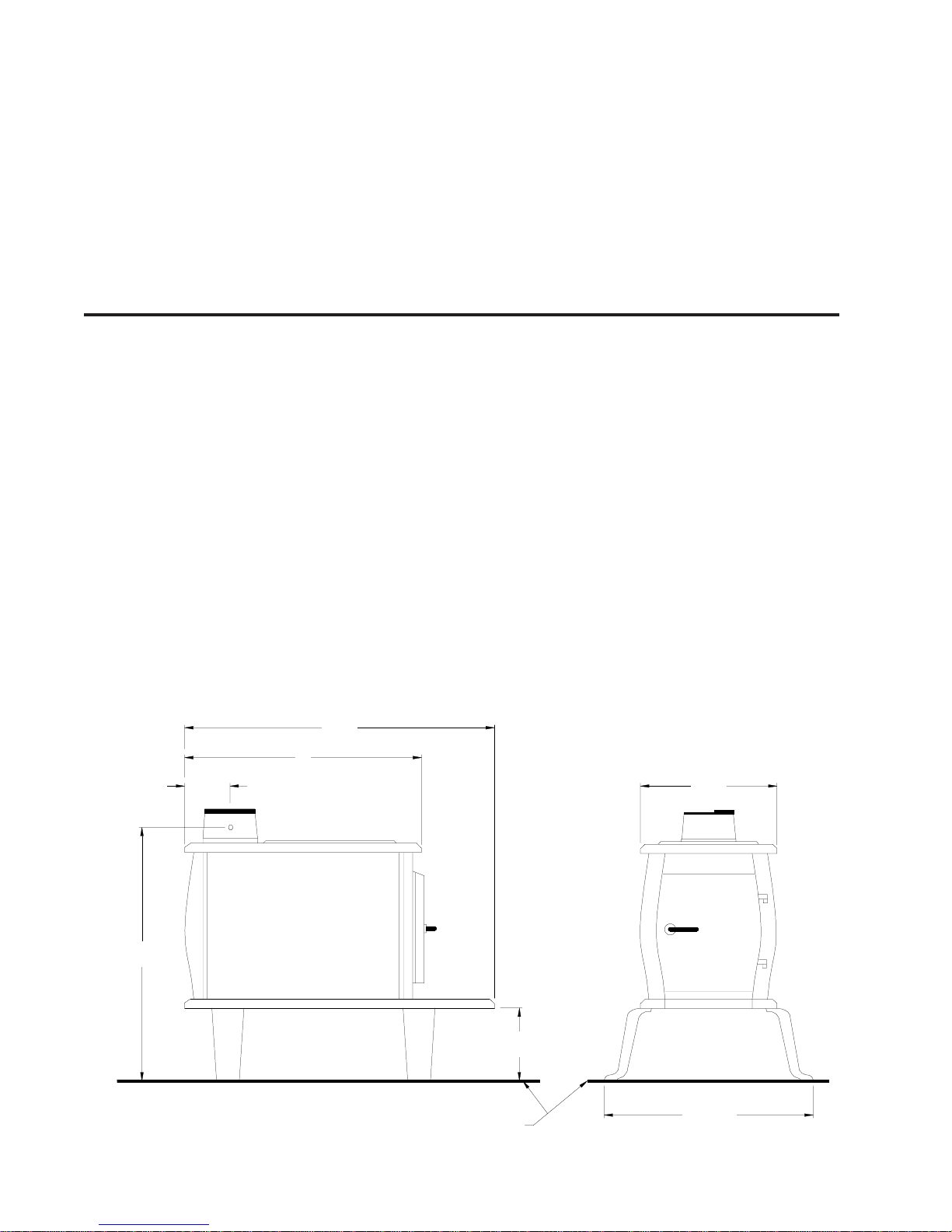
Donot expecta heaterto draw. Itis thechimney thatcreates
thedraft.Smokespillageintothehouseorexcessivebuildup
of water or creosote in the chimney are warnings that the
chimney is not functioning properly. Correct problem before
using heater. Possible causes are:
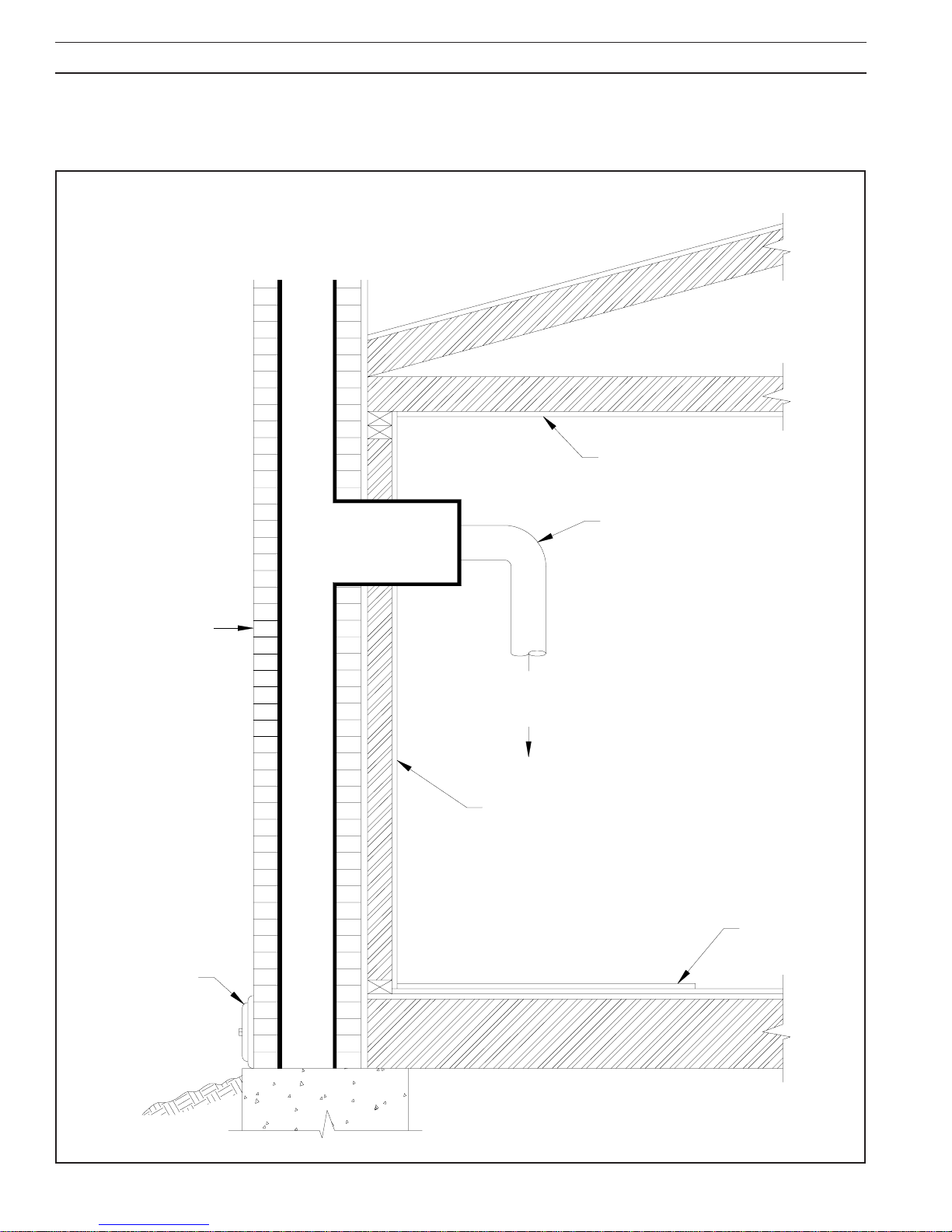
The connector pipe may push into the chimney too far,
stopping the draft. (Fig. 7)
Donot connect two heaters into the same chimney flue.
The chimney used for a heater must not be used to
ventilate the cellar or basement. If there is a cleanout
opening at the base of the chimney, It must be closed
tightly.
1.
2.
3.
4.
5.
Ifthe chimneyis operatingtoo cool,water willcondense
in the chimney and run back into the stove. Creosote
formation will be rapid and may block the chimney.
Operate the heater at a high enough fire to keep the
chimney warm preventing this condensation.
If the fire burns well but sometimes smokes or burns
slowly,itmaybecaused bythechimneytopbeing lower
thananotherpartofthehouseoranearbytree.Thewind
blowingover a house or tree, fallsontop of the chimney
likewaterover adam, beatingdownthe smoke.The top
of the chimney should be at least 3 feet above the roof
and be at least to 2 feet higher than any point of the roof
within 10 feet (Fig. 6).
WARNING!WARNING!
WARNING!WARNING!
WARNING!
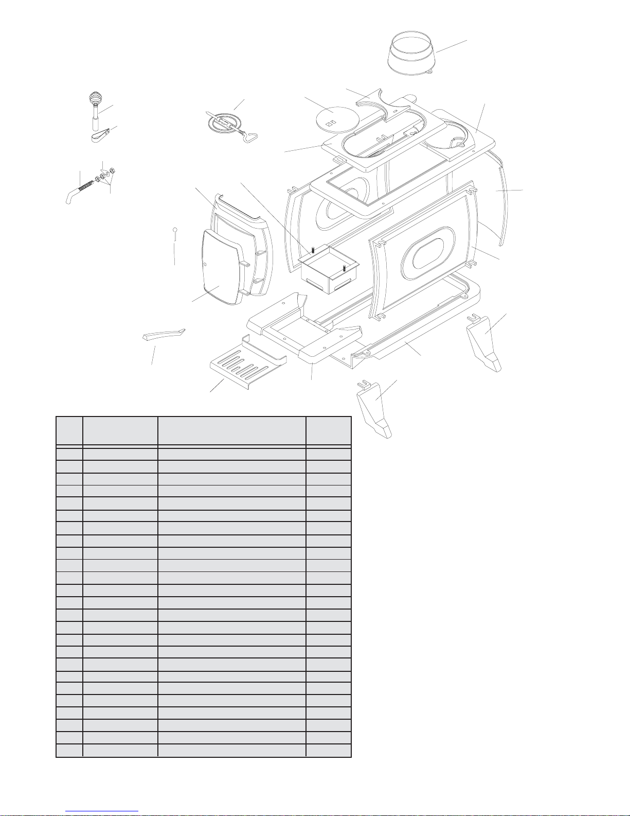
USE ONLY THE LEGS PROVIDED WITH THISUSE ONLY THE LEGS PROVIDED WITH THIS
USE ONLY THE LEGS PROVIDED WITH THIS
HEATER. REFER TO STEP 5 IN THE "INSTAL-HEATER. REFER TO STEP 5 IN THE "INSTAL-
HEATER. REFER TO STEP 5 IN THE "INSTAL-
LATION" SECTION OF THIS MANUAL.LATION" SECTION OF THIS MANUAL.
LATION" SECTION OF THIS MANUAL.
WARNING!WARNING!
WARNING!WARNING!
WARNING!
DO NOT OBSTRUCT THE SPACE BENEATHDO NOT OBSTRUCT THE SPACE BENEATH
DO NOT OBSTRUCT THE SPACE BENEATH
THE HEATERTHE HEATER
THE HEATER

Model C226Model C226
Model C226
Repair PartsRepair Parts
Repair Parts
1010
1010
10
* NOT SHOWN* NOT SHOWN
* NOT SHOWN
KEYKEY
KEYKEY
KEY
11
11
1
22
22
2
33
33
3
44
44
4
55
55
5
66
66
6
77
77
7
88
88
8
99
99
9
1010
1010
10
1111
1111
11
1212
1212
12
1313
1313
13
1414
1414
14
1515
1515
15
1616
1616
16
1717
1717
17
1818
1818
18
1919
1919
19
2020
2020
20
2121
2121
21
2222
2222
22
2323
2323
23
**
**
*
**
**
*
PART NO.PART NO.
PART NO.PART NO.
PART NO.
4029640296
4029640296
40296
4031840318
4031840318
40318
4029740297
4029740297
40297
4029840298
4029840298
40298
4029940299
4029940299
40299
4030040300
4030040300
40300
4030140301
4030140301
40301
4030240302
4030240302
40302
4030340303
4030340303
40303
4030440304
4030440304
40304
4030540305
4030540305
40305
4030640306
4030640306
40306
4030740307
4030740307
40307
4030840308
4030840308
40308
4033240332
4033240332
40332
D6D6
D6D6
D6
8342783427
8342783427
83427
6930769307
6930769307
69307
8997489974
8997489974
89974
8997589975
8997589975
89975
8997189971
8997189971
89971
8997289972
8997289972
89972
8997389973
8997389973
89973
8958989589
8958989589
89589
851475851475
851475851475
851475
DESCRIPTIONDESCRIPTION
DESCRIPTION
REAR LEGREAR LEG
REAR LEGREAR LEG
REAR LEG
FRONT LEGFRONT LEG
FRONT LEGFRONT LEG
FRONT LEG
MAIN BOTTOMMAIN BOTTOM
MAIN BOTTOM
MAIN SIDEMAIN SIDE
MAIN SIDEMAIN SIDE
MAIN SIDE
MAIN BACKMAIN BACK
MAIN BACKMAIN BACK
MAIN BACK
HEARTH PLATEHEARTH PLATE
HEARTH PLATE
SLIDING DRAFT PLATESLIDING DRAFT PLATE
SLIDING DRAFT PLATE
DOOR FRAMEDOOR FRAME
DOOR FRAME
DOORDOOR
DOORDOOR
DOOR
MAIN TOPMAIN TOP
MAIN TOPMAIN TOP
MAIN TOP
PIVOTING TOPPIVOTING TOP
PIVOTING TOP
LIDLID
LIDLID
LID
LID SUPPORTLID SUPPORT
LID SUPPORT
LID LIFTERLID LIFTER
LID LIFTER
FLUE COLLARFLUE COLLAR
FLUE COLLAR
SOLID FLUE DAMPERSOLID FLUE DAMPER
SOLID FLUE DAMPER
DOOR PINSDOOR PINS
DOOR PINSDOOR PINS
DOOR PINS
BAFFLE ASSEMBLYBAFFLE ASSEMBLY
BAFFLE ASSEMBLY
HANDLE EXTENSIONHANDLE EXTENSION
HANDLE EXTENSION
HANDLE BRACKETHANDLE BRACKET
HANDLE BRACKET
HANDLEHANDLE
HANDLEHANDLE
HANDLE
LATCHLATCH
LATCHLATCH
LATCH
NUTSNUTS
NUTSNUTS
NUTS
PARTS BAGPARTS BAG
PARTS BAGPARTS BAG
PARTS BAG
OWNERS MANUALOWNERS MANUAL
OWNERS MANUAL
QTY.QTY.
QTY.QTY.
QTY.
22
22
2
22
22
2
11
11
1
22
22
2
11
11
1
11
11
1
11
11
1
11
11
1
11
11
1
11
11
1
11
11
1
22
22
2
11
11
1
11
11
1
11
11
1
11
11
1
22
22
2
11
11
1
11
11
1
11
11
1
11
11
1
11
11
1
33
33
3
11
11
1
11
11
1
1919
1919
19
2020
2020
20
2222
2222
22
2323
2323
23
2121
2121
21
1616
1616
16 1212
1212
12 1313
1313
13
1515
1515
15
1010
1010
10
55
55
5
44
44
4
11
11
1
33
33
3
22
22
2
66
66
6
1414
1414
14
1717
1717
17
1818
1818
18
88
88
8
1111
1111
11
77
77
7
99
99
9

1111
1111
11
BAFFLE AND FLUE COLLAR ASSEMBLYBAFFLE AND FLUE COLLAR ASSEMBLY
BAFFLE AND FLUE COLLAR ASSEMBLY

HOHO
HOHO
HOWW
WW
W TT
TT
TO ORDER REPO ORDER REP
O ORDER REPO ORDER REP
O ORDER REPAIR PAIR P
AIR PAIR P
AIR PARAR
ARAR
ARTSTS
TSTS
TS
THIS MANUAL WILL HELP YOU OBTAIN EFFICIENT, DEPENDABLE SERVICE FROMTHIS MANUAL WILL HELP YOU OBTAIN EFFICIENT, DEPENDABLE SERVICE FROM
THIS MANUAL WILL HELP YOU OBTAIN EFFICIENT, DEPENDABLE SERVICE FROM
THE HEATER, AND ENABLE YOU TO ORDER REPAIR PARTS CORRECTLY.THE HEATER, AND ENABLE YOU TO ORDER REPAIR PARTS CORRECTLY.
THE HEATER, AND ENABLE YOU TO ORDER REPAIR PARTS CORRECTLY.
KEEP IN A SAFE PLACE FOR FUTURE REFERENCE.KEEP IN A SAFE PLACE FOR FUTURE REFERENCE.
KEEP IN A SAFE PLACE FOR FUTURE REFERENCE.
WHEN WRITING, ALWAYS GIVE THE FULL MODEL NUMBER WHICH IS ON THEWHEN WRITING, ALWAYS GIVE THE FULL MODEL NUMBER WHICH IS ON THE
WHEN WRITING, ALWAYS GIVE THE FULL MODEL NUMBER WHICH IS ON THE
NAMEPLATE ATTACHED TO THE BACK OF THE HEATER.NAMEPLATE ATTACHED TO THE BACK OF THE HEATER.
NAMEPLATE ATTACHED TO THE BACK OF THE HEATER.
WHEN ORDERING REPAIR PARTS, ALWAYS GIVE THEWHEN ORDERING REPAIR PARTS, ALWAYS GIVE THE
WHEN ORDERING REPAIR PARTS, ALWAYS GIVE THE
FOLLOWING INFORMATION AS SHOWN IN THIS LIST:FOLLOWING INFORMATION AS SHOWN IN THIS LIST:
FOLLOWING INFORMATION AS SHOWN IN THIS LIST:
1. The PART NUMBER1. The PART NUMBER
1. The PART NUMBER
2. The PART DESCRIPTION2. The PART DESCRIPTION
2. The PART DESCRIPTION
3. The MODEL NUMBER: C2263. The MODEL NUMBER: C226
3. The MODEL NUMBER: C226
4. The SERIAL NUMBER:4. The SERIAL NUMBER:
4. The SERIAL NUMBER:
UNITED STATES STOVE COMPANYUNITED STATES STOVE COMPANY
UNITED STATES STOVE COMPANY
227 Industrial Park Road227 Industrial Park Road
227 Industrial Park Road
P.O. Box 151P.O. Box 151
P.O. Box 151
South Pittsburg, TN 37380South Pittsburg, TN 37380
South Pittsburg, TN 37380
(423) 837-2100(423) 837-2100
(423) 837-2100(423) 837-2100
(423) 837-2100
www.USSTOVE.comwww.USSTOVE.com
www.USSTOVE.com
Table of contents
Other USSC Heater manuals

USSC
USSC 4027 User manual

USSC
USSC 2007 User manual

USSC
USSC Logwood 1261 User manual

USSC
USSC Logwood C242 User manual

USSC
USSC Wondercoal 2827 User manual

USSC
USSC DR6 Manual

USSC
USSC Wondercoal 2927 User manual

USSC
USSC King 2007B User manual

USSC
USSC VF30IL User manual

USSC
USSC Wondercoal 2941 User manual
Popular Heater manuals by other brands

Helios
Helios KWL-EVH 170 W Installation and operating instructions

Lamborghini Caloreclima
Lamborghini Caloreclima INOX TECH 45 H Instructions for use, installation and maintenance

Uberhaus
Uberhaus 68125104 Operator's manual

TPI
TPI 2600 Series installation instructions

Pifco
Pifco PE108 Safety & instruction manual

ElectrIQ
ElectrIQ EAH2000W user manual