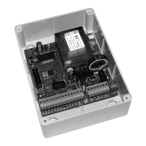
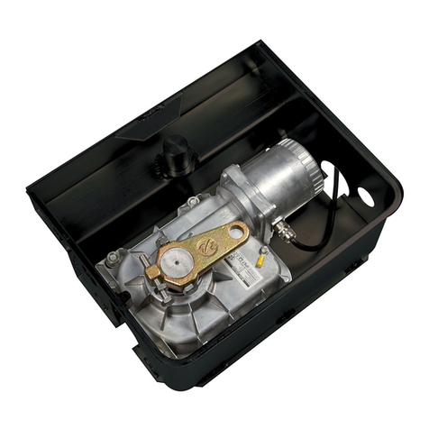
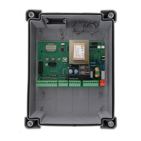
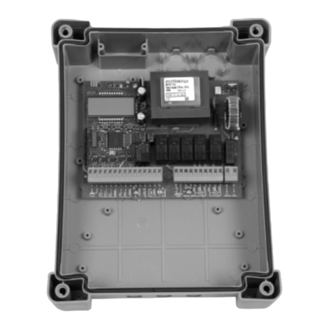
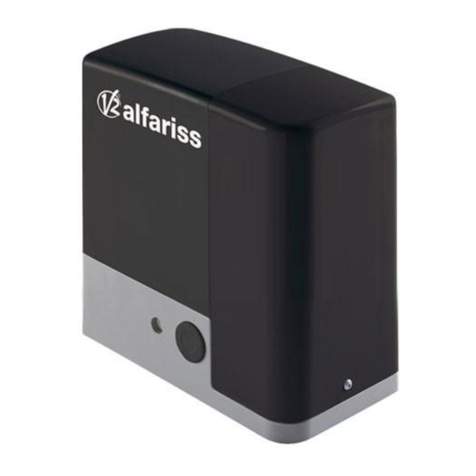
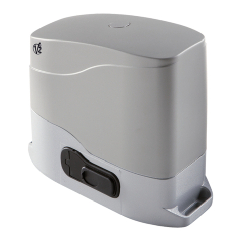
V2 Calypso400 User manual

ATTUATORE ELETTROMECCANICO IRREVERSIBILE PER CANCELLI A BATTENTE
ISTRUZIONI D'USO E INSTALLAZIONE
IRREVERSIBLE ELECTROMECHANICAL ACTUATOR FOR LEAF GATES OPERATING AND
INSTALLATION INSTRUCTIONS
OPERATEUR ELECTROMECANIQUE IRREVERSIBLE POUR PORTAILS À BATTANT
NOTICES D’EMPLOI ET D’INSTALLATION
NICHT UMKEHRBARER ELEKTROMECHANISCHER ANTRIEB FÜR FLÜGELTORE
BEDIENUNGSANLEITUNGEN UND INSTALLATION
OPERADOR ELECTROMECANICO IRREVERSIBLE PARA CANCELAS BATIENTES
INSTRUCCIONES DE USO E INSTALACION
I
GB
F
D
E
CALYPSO
IL n.186-A
EDIZ. 30/11/2006
V2 ELETTRONICA SPA
Corso Principi di Piemonte, 65/67 - 12035 RACCONIGI (CN) ITALY
tel. +39 01 72 81 24 11 fax +39 01 72 84 050
info@remotecontrolgates.co.uk www.remotecontrolgates.co.uk

ENGLISH
8
TECHNICAL DATA
Calypso400 Calypso500 Calypso
400-120V
Calypso
500-120V
Max. leaf lenght m2,5 32,5 3
Max. leaf weight Kg 400 500 400 500
Power supply VAC - Hz 230 - 50 230 - 50 120 - 60 120 - 60
Idling current A 1 1 2 2
Full load current A 1,4 1,4 2,8 2,8
Maximum Power W 300 300 300 300
Capacitor µF 8 8 25 25
Max travel mm 400 500 400 500
Operating speed m/s 0,016 0,016 0,018 0,018
Maximum thrust N 2600 2600 2600 2600
Working temperature °C -30 ÷ +60 -30 ÷ +60 -30 ÷ +60 -30 ÷ +60
Protection IP 44 44 44 44
Working cycle % 30 30 30 30
Motor weight Kg 6,5 6,8 6,5 6,8
Calypso400 Calypso500
A819 944
B762 887
C1162 1387

ENGLISH
9
INSTALLATION LAYOUT
1CALYPSO actuator cable 4 x 1 mm2
2Blinker cable 2 x 1,5 mm2
3Aerial cable RG-58
4Key or digital selector cable 2 x 1 mm2
5Internal photocells cable 4 x 1 mm2(RX)
cable 2 x 1 mm2(TX)
6External photocells cable 4 x 1 mm2(RX)
cable 2 x 1 mm2(TX)
7Control unit cable 3 x 1,5 mm2
PREPARATORY STEPS
The new series of actuadors CALYPSO, has been devised to serve gates up to 500 Kg with leaf up to 3 meters wide (look at the table
technical data). Before proceeding with the installation, please make sure that your gate opens and closes freely, and that:
•Hinges and pins are in optimum condition and properly greased.
• No obstacles are within the moving area.
•There is no friction with the ground or between the leaves.
• Your gate shall be equipped with central Aand side Bstops, which are fundamental for the good system operation.

ENGLISH
10
INSTALLATION MEASURES
To carry out a proper installation of the operator parts as well
as to ensure the best automation performance, the
measurement levels shown in the following table shall be
complied with. Change the gate structure to adapt it to one of
the cases in the table, if necessary.
mWARNING: In the case of leaf longer than 2 metres, an
electric lock must be fitted to ensure an efficent closig.
CALYPSO 400
γγA [mm] B [mm] C [mm] F [mm]
90°
20 130 130 1010
40 150 140 1000
60 170 150 990
80 190 150 980
100 200 150 980
120 210 140 980
140 250 120 1010
100°
20 130 170 970
40 150 180 960
60 170 180 960
80 190 170 970
100 210 140 990
110°
20 130 190 950
40 150 180 960
50 160 170 970
CALYPSO 500
γγA [mm] B [mm] C [mm] F [mm]
90°
20 130 170 1200
40 150 180 1190
60 170 180 1190
80 190 190 1180
100 210 190 1170
120 230 190 1170
140 250 180 1170
160 270 190 1170
180 290 170 1180
100°
20 130 160 1210
40 150 170 1200
60 170 170 1200
80 200 180 1190
100 210 170 1190
120 230 190 1170
140 250 180 1180
160 270 160 1200
170 280 160 1200
110°
20 130 170 1200
40 150 180 1190
60 170 180 1190
80 190 190 1180
100 210 200 1170
110 220 200 1170

ENGLISH
11
ACTUATOR FIXING
Choose measures referring to the table you can find in the
previous page, mark them on the pillars and continue as
follows:
• Fix the clamps to the pillar and to the gate soldering
directly; if the material does not allow it, it is necessary to
solder the clamps to plates to be fixed to the gate and the
pillars by screws.
•Close the swing.
•Unlock the actuators.
• Position CALYPSO on the brackets and fix the pins no. 1 and
no. 2 with seeger (see the picture).
• Open and close the swings repeatedly manually to verify the
absence of frictions between gate and ground.
mWARNING: in order to avoid damage to the actuator,
please adhere to the following conditions:
• The brackets must be installed at the same height.
• The maximum stroke of arm A should not exceed 456 mm
for CALYPSO400 and 556 mm for CALYPSO500 (in case of
gate completely closed).
•The minimum stroke of arm B must be more than 56 mm (in
case of gate completely open).

ENGLISH
TO CONNECT CALYPSO WITH CONTROL UNIT
mWARNING: always remember to connect the earth according
to current standards (EN 60335-1, EN 60204-1).
EMERGENCY RELEASE
In case of a blackout, the gate can be
operated directly from the motor. Insert the key
supplied in the lock, perform 1/2 of a turn.
To restore the automation, simply rotate the
key in closed position and insert the provided
plastic cover onto the lock.
1YELLOW - GREEN GND
2BLUE (230V mod.)
WHITE (120V mod.) COMMON
3BLACK CLOSING
4BROWN OPENING
12

CENTRALE DI COMANDO ANALOGICA PER
CANCELLI A BATTENTE
ANALOGUE CONTROL UNIT FOR SWING GATES
ARMOIRE DE COMMANDE ANALOGIQUE POUR
PORTAILS BATTANTS
CUADRO DE MANIOBRA ANALÓGICO PARA
CANCELAS A BATIENTE
QUADRO DE COMANDO ANALÓGICO PARA
PORTÕES DE BATENTE
I
GB
F
E
P
IL n. 252-1
EDIZ. 12/11/2007
V2 S.p.A.
Corso Principi di Piemonte, 65/67 - 12035 RACCONIGI (CN) ITALY
tel. +39 01 72 81 24 11 fax +39 01 72 84 050
[email protected] www.v2home.com
City7 (Pr. 1.0)

ENGLISH
8
ELECTRICAL CONNECTION TABLE
L1 Antenna
L2 Antenna shield
L3 Opening command for a standard connection device
with switch normally open.
L4 Pedestrian opening command for a standard
connection device with switch normally open.
L5 STOP command. N.C. switch
L6 Photocell. N.C. switch
L7 Edge. Switch N.C. or resistive rubber edge
L8 Commands common (-) line
L9 - L10 24 VAC power output for photocells and other
accessories
L10 - L11 Power supply for functional test TX photocell
K1 - K2 Courtesy light timer activation switch
K3 Motor 1 open
K4 Motor 1 common
K5 Motor 1 close
K6 Motor 2 open
K7 Motor 2 common
K8 Motor 2 closed
K9 - K10 230V - 40W / 120V - 40W blinker
N230V / 120V power supply - neutral
L230V / 120V power supply - phase
J1 NOT USED
ADJUSTMENT OF THE POWER AND
OPERATIONAL TIMES
The power and operating times may be adjusted by means of 4
trimmers located on the control unit:
POWER: motor power.
WORK: motor operating time (5 - 120 seconds).
m PLEASE NOTE: it is recommended that operating times be
set with the slow down function disabled (DIP 5 OFF).
PAUSE: pause time before automatic re-closure
(5 - 120 seconds).
DELAY: time delay between the two gate leaves
(0 - 60 seconds).
CONTROL UNIT INDICATORS (LEDS)
The highlighted boxes indicate the state of the LEDs when the
gate is resting.
mPLEASE NOTE: If
not used, the normally
closed inputs (STOP,
PHOTO, EDGE) must be
jumpered with the
commands common line
COM (-)
LED ON OFF
START START input closed START input open
IN2 START P. input closed START P. input open
STOP STOP input closed STOP input open
PHOTO PHOTO input closed PHOTO input open
EDGE
Standard edge
EDGE input closed (edge
not pressed)
EDGE input open (edge
pressed)
Resistive rubber edge
EDGE input closed (edge
pressed) EDGE input open
(fault)
Edge NO pressed: 8K2
between EDGE input
and common (-)
mains Control unit powered-up Control unit NOT powered-up
overload Accessory power supply
overload
Accessory power supply within
normal operational limits
J1

ENGLISH
9
INSTALLATION
Installation of the control unit, the safety devices and accessories
must be performed with the power supply disconnected.
POWER SUPPLY
The control unit must be powered by means of a 230 V - 50 Hz
or 120 V - 60 Hz power line, depending on the model, protected
by a differential magnetothermal switch in compliance with legal
regulations.
Connect the power cables to the control unit Land Nterminals.
MOTORS
The control unit can control one or two asynchronous AC motors.
If the control unit is used to control only one motor, then this
must be connected to the terminals relating to motor 1.
Connect the cables for motor 1 as follows:
• Opening cable to terminal K3
• Closing cable to terminal K5
• Common return cable to terminal K4
• Start-up capacitor between terminals K3 and K5
Connect the cables for motor 2 (if present) as follows:
•Opening cable to terminal K6
•Closing cable to terminal K8
•Common return cable to terminal K7
• Start-up capacitor between terminals K6 and K8
BLINKER
The control unit provides for the use of a 230V - 40W or
120V - 40W blinker with built-in intermittence.
Connect the cables to terminals K9 and K10.
COURTESY LIGHT
This output has a normally-open clean contact relay which closes
for approx. 1 second at the start of an opening phase. This
switch may be used to activate a courtesy light timer (max. load:
230V - 4 A).
PLEASE NOTE: If there is no timer, the courtesy light can be
controlled using channel 4 of receiver MR1: bistable or timer
programmable channel (read the instructions for the receiver MR1
thoroughly).
The switch is on terminals K1 and K2.
PHOTOCELLS
The control unit has a 24VAC power supply for photocells with
switch normally closed, and can perform an operational test
before to starting the gate opening procedure.
The photocell can be used with two settings:
1. Photocell always active:
Intervention of the photocell during opening or closing
causes the gate to stop.
When the photocell restores, the gate re-opens completely.
2. Photocell NOT active during opening:
Intervention of the photocell during opening is ignored.
Intervention of the photocell during closing causes the gate
to re-open completely.
Independently of the setting selected, when the gate is paused
while opening, the time count for any automatic re-closure will
only start after the photocell restores.
•Connect the photocell transmitter power cables between
terminals L10 (GND) and L11 (+) on the control unit.
• Connect the photocell receiver power cables between
terminals L10 (GND) and L9 (+) on the control unit.
• Connect the photocell receiver output between terminals L6
and L8 on the control unit.
SAFETY EDGES
The control unit has an input for controlling safety edges; this
input is capable of controlling standard edges with switch
normally closed and conductive rubber edges with nominal
resistance of 8.2 kOhms.
Edges can be used with two settings:
1. Edge always active:
Intervention of the edge during opening or closing causes
inversion of the direction of movement in order to free the
body that caused the edge to intervene.
The gate stops after approx. 3 seconds.
2. Edge NOT active during opening:
Intervention of the edge during opening is ignored.
Intervention of the edge during closing causes the gate to
re-open completely.
Independently of the settings selected, any subsequent automatic
re-closure will be cancelled.
Standard edge with switch normally closed: connect the
edge cables between terminals L7 and L8 on the control unit.
In order to satisfy the requirements of standard EN12978, it is
necessary to install safety edges with a control unit which
constantly monitors correct operation. If control units are used
with the option of running tests by means of interrupting the
power supply, connect the control unit power supply cables
between terminals L10 (GND) and L11 (+).

ENGLISH
10
Conductive rubber edge: connect the edge cables between
terminals L7 and L8 on the control unit.
mPLEASE NOTE: operational testing on edges is reserved for
standard edges (only if equipped with suitable control units).
DO NOT enable testing if conductive rubber edges are used
or standard edges used without a suitable control unit for
controlling function.
mNOTE: use the special interface (code 35A024) for
connection of the optical bars, de-activating the operational test
on the bars.
START INPUT
The START input is preset for connecting devices with the switch
normally open. Function depends on the mode of operation set
by means of dip-switch 4.
Step mode
Subsequent Start command cause, in order:
rt opening rt stop rt closure rt stop r
“Inversion” mode
Start during opening causes closure.
Start during closure causes opening.
Start with the gate open always results in closure;
The only case where this does not occur immediately is when
automatic closure is enabled and start while opening is not
accepted: in this specific case, start makes the pause time count
start from zero, after which the gate will be re-closed.
In both modes it is possible to disable the Start command during
gate opening by means of dip-switch 3.
Connect the start input control device cables between terminals
L3 and L8 on the control unit.
PEDESTRIAN START
With the gate closed, the pedestrian start command causes
partial opening (approx. half way) of the gate leaf connected to
motor 1. Subsequent pedestrian start commands will function
according to step logic.
During a pedestrian cycle, the start command results in the
complete opening of both gate leaves.
Connect the pedestrian start input control device cables between
terminals L4 and L8 on the control unit.
STOP
The STOP input is intended for devices with the switch normally
closed.
The STOP command causes the immediate stop of the gate.
Asubsequent START command activates the gate in the opposite
direction of movement.
If the STOP command is given during opening or pause, then
there will be no subsequent automatic re-closure.
Connect the stop input control device cables between terminals
L5 and L8 on the control unit.
PLUG-IN RECEIVER
The control unit is suitable for plugging-in an MR1 series receiver
with high sensitivity super-heterodyne architecture.
mPLEASE NOTE: Disconnect the power to the control unit
before performing the following operations. Pay the utmost
attention to the direction of insertion of plug-in modules.
The MR1 receiver module has 4 channels, each with an
associated command on the City7 control unit:
• CHANNEL 1 r
rt
tSTART
•CHANNEL 2 r
rt
tPEDESTRIAN START
• CHANNEL 3 r
rt
tSTOP
•CHANNEL 4 r
rt
tCOURTESY LIGHTS
mPLEASE NOTE:
Read the instructions supplied with the MR1 receiver thoroughly
for details on programming the 4 channels and the operational
logic.
EXTERNAL ANTENNA
It is recommended the external antenna be used in order to
guarantee maximum radio capacity.
Connect the antenna hot pole to terminal L1 of the control unit
and the braiding to terminal L2.

ENGLISH
11
PROGRAMMING THE OPERATIONAL LOGIC
It is possible for the control unit to use several different operational logic states, by simply moving the dip-switches located on the card.
The functions associated with each individual dip-switch are listed below.
DIP FUNCTION SETTING DESCRIPTION
1 Pre-flashing ON Disabled The blinker is switched on when the motors are started
OFF Enabled The blinker is switched on for 2 seconds before the motors are started
2Automatic
closure
ON Enabled The gate is closed automatically after the period of time set by the PAUSE
trimmer
OFF Disabled On completion of the opening step, the gate remains open. It is necessary to
instruct closure with another START command
3 Start opening ON Not accepted Any START command issued during opening is ignored
OFF Accepted Any START command issued during opening is accepted
4 Operational logic
ON Inversion Start during opening causes closure.
Start during closure causes opening.
OFF Step Commands subsequent to starting cause, in order:
open rt stop rt close rt stop...
5 Slow down ON Enabled At the end of each opening and closing step, the motors slow down in order to
avoid noisy closure and bouncing.
OFF Disabled
6 Start off ON Disabled At the start of each opening and closing step, the motors are started at
maximum power
OFF Enabled
7 Anti-slip
ON Disabled
The time used for opening or closure will always be the value set by the WORK
trimmer, even if the previous operation has been interrupted before the expiry
of such time.
OFF Enabled
When an opening (or closing) operation is interrupted before expiry of the set
time (for example due to the intervention of one of the safety devices or due to
a start command), the duration of the subsequent closing (or opening)
operation will not be that set by the WORK trimmer, but will be equal to the
time effectively elapsed, plus a short supplemental time in order to compensate
for the inertia of the gate.
8 Photocell
ON Always active Intervention of the photocell during opening or closing causes the gate to stop.
When the photocell restores, the gate re-opens completely.
OFF NOT active during
opening:
Intervention of the photocell during opening is ignored. Intervention of the
photocell during closing causes the gate to re-open completely.
9 Photocell test
ON Enabled The control unit performs a photocell operational test before starting each
opening or closing operation. If the photocells are not operating correctly, the
gate does not begin to move and the light flashes for approx. 8 seconds.
PLEASE NOTE: connect the photocell TX correctly
OFF Disabled
10 Safety edge
type
ON Conductive rubber
edge
Select this option if using conductive rubber edges with nominal resistance of
8K2.
OFF Standard or optical
edge
Select this option if using standard edges with switch normally closed or optical
edges.
11 Safety edge
ON Always active
Intervention of the edge during opening or closing causes inversion of the
direction of movement in order to free the body that caused the edge to
intervene. The gate will be stopped after approx. 3 seconds.
OFF NOT active during
opening:
Intervention of the edge during opening is ignored. Intervention of the edge
during closing causes the gate to be re-opened completely.
12 Safety edge test
ON Enabled The control unit performs an operational test on the edges before starting each
opening or closing operation. If the edges are not operating correctly, the gate
does not begin to move and the light flashes for approx. 8 seconds.
DO NOT enable testing if conductive rubber edges are used or standard
edges are used without a suitable control unit for controlling function.
OFF Disabled
This manual suits for next models
3
Table of contents
Other V2 Garage Door Opener manuals