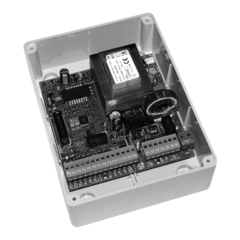
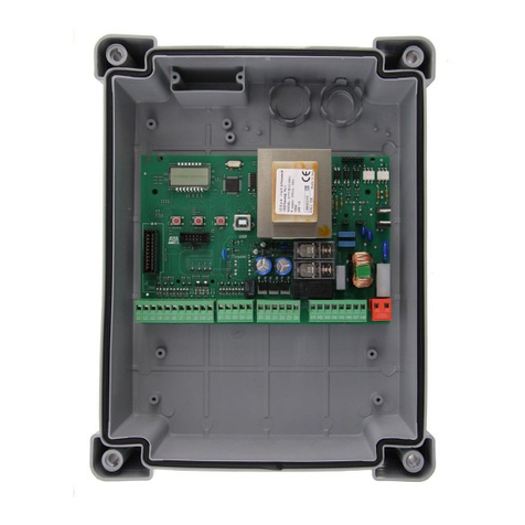
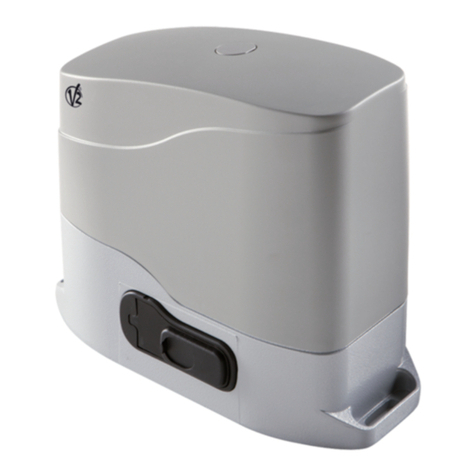
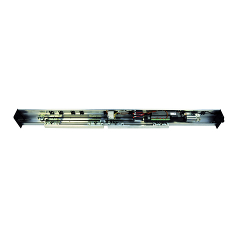
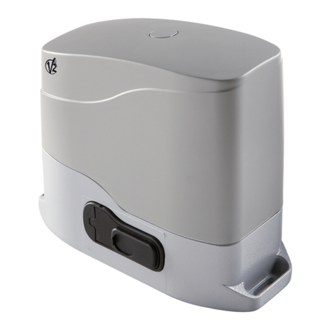
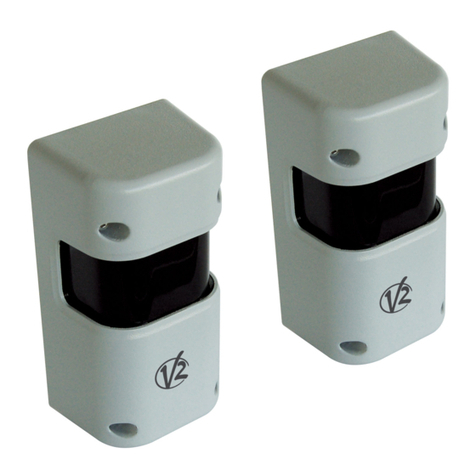
V2 HYPERFOR User manual

ZIS380
IL 404-1
EDIZ. 28/01/2019
HYPERFOR
I
ATTUATORE ELETTROMECCANICO
400V IRREVERSIBILE A CREMAGLIERA
PER CANCELLI SCORREVOLI FINO A
4000 KG DI PESO
GB
400V ELECTRO-MECHANICAL
IRREVERSIBLE RACK ACTUATOR
FOR SLIDING GATES UP TO 4000 KG
F
OPERATEUR ELECTROMECANIQUE
400V IRREVERSIBLE A CREMAILLERE
POUR PORTAILS COULISSANTS
JUSQU’A 4000 KG DE POIDS
E
MOTOR ELECTROMECANICO 400V
IRREVERSIBLES A CREMALLERA
PARA PUERTAS CORREDERAS
HASTA 4000 KG DE PESO

629 mm
565 mm
323 mm
290 mm

ITALIANO
- 27 -
23 - ANOMALIE DI FUNZIONAMENTO
In questo paragrafo vengono elencate alcune anomalie di funzionamento che si possono presentare, ne viene indicata la causa e la
procedura per porvi rimedio.
VISUALIZZAZIONE DESCRIZIONE SOLUZIONE
Led MAINS spento Alimentazione della parte logica assente Controllare il fusibile F1
Led OVERLOAD acceso Alimentazione accessori 24V sovraccarica 1. Estrarre la morsettiera H1 - H8: il led
OVERLOAD si spegne
2. Eliminare la causa del sovraccarico
(morsetti E1-E3)
3. Reinnestare lla morsettiera e verificare
che il led non si accenda nuovamente
Prelampeggio prolungato del
LAMPEGGIANTE
Quando viene dato un comando di start il
lampeggiante si accende immediatamente,
ma il cancello tarda ad aprirsi: è scaduto il
conteggio di cicli impostato per l’intervento
di manutenzione (Service)
Accedere al menù dei contatori e
reimpostare il parametro Service
Il display visualizza ERR1 Errore software Inviare la centrale in riparazione
Il display visualizza ERR3 Il test di funzionamento delle fotocellule è
fallito
1. Verificare che non ci siano ostacoli tra le
fotocellule
2. Verificare che le fotocellule abilitate da
menu siano effettivamente installate e
funzionanti
3. Se vengono usate fotocellule di tipo 2,
assicurarsi che la voce di menu FOT2 sia
impostata su CFCH
4. Verificate le condizioni precedenti, se
l’errore persiste, aumentare il tempo del
test (parametro FT.TE)
Il display visualizza ERR4 Errore finecorsa Verificare che i finecorsa siano collegati
correttamente e che gli switch finecorsa si
attivino con il movimento del cancello
Il display visualizza ERR5 Il test di funzionamento delle coste di
sicurezza è fallito
1. Verificare che le coste abilitate da
menù siano effettivamente installate e
funzionanti
2. Assicurarsi che la centralina di controllo
delle coste sia collegata correttamente e
funzionante
Il display visualizza ERR6 Errore sensore amperometrico Se l’errore persiste inviare la centrale in
riparazione
Il display visualizza ERR7 Errore encoder Verificare il collegamento dell’encoder
Il display visualizza ERR9 Accesso al menù di programmazione
bloccato tramite CL1+
Inserire il modulo CL1+ con cui è stata
bloccata la programmazione nel connettore
ADI: la centrale entra automaticamente nel
menù di programmazione PRG
Il display visualizza ERR10 Il test di funzionamento delle sicurezze
collegate all’interfaccia ADI è fallito
Verificare che il modulo ADI sia connesso
Verificare che le sicurezze collegate
all’interfaccia ADI sia collegate
correttamente e funzionanti
Il display visualizza HALT Stop di emergenza attivo Disattivare il pulsante di STOP tra i morsetti
T1 e T2.
Se non è installato un interruttore i due
morsetti devono essere ponticellati

ITALIANO
- 28 -
24 - COLLAUDO E MESSA IN SERVIZIO
Queste sono le fasi più importanti nella realizzazione
dell’automazione al fine di garantire la massima sicurezza.
V2 raccomanda l’utilizzo delle seguenti norme tecniche:
• EN 12445 (Sicurezza nell’uso di chiusure automatizzate, metodi
di prova)
• EN 12453 (Sicurezza nell’uso di chiusure automatizzate,
requisiti)
• EN 60204–1 (Sicurezza del macchinario, equipaggiamento
elettrico delle macchine, parte 1: regole generali)
In particolare, facendo riferimento alla tabella del paragrafo
“VERIFICHE PRELIMINARI e IDENTIFICAZIONE DELLA TIPOLOGIA
DI UTILIZZO” nella maggior parte dei casi sarà necessaria la misura
della forza d’impatto secondo quanto previsto dalla norma EN
12445.
La regolazione della forza operativa è possibile tramite la
programmazione della scheda elettronica e Il profilo delle forze di
impatto deve essere misurato con un apposito strumento (anche
lui certificato e sottoposto a taratura annuale) in grado di tracciare
il grafico forza-tempo.
Il risultato deve rispettare i seguenti valori massimi:
25 - MANUTENZIONE
La manutenzione deve essere effettuata nel pieno rispetto
delle prescrizioni sulla sicurezza del presente manuale e
secondo quanto previsto dalle leggi e normative vigenti.
L’intervallo raccomandato tra ogni manutenzione è di sei
mesi, le verifiche previste dovrebbero riguardare almeno:
• la perfetta efficienza di tutti i dispositivi di segnalazione
• la perfetta efficienza di tutti i dispositivi di sicurezza
• la misurazione delle forze operative del cancello
• la lubrificazione delle pari meccaniche dell’automazione
(dove necessario)
• lo stato di usura delle parti meccaniche
dell’automazione
• lo stato di usura dei cavi elettrici degli attuatori
elettromeccanici
L’esito di ogni verifica và annotato in un registro di
manutenzione del cancello.
26 - SMALTIMENTO
Come per le operazioni d’installazione, anche al
termine della vita di questo prodotto, le operazioni di
smantellamento devono essere eseguite da personale
qualificato.
Questo prodotto è costituito da vari tipi di materiali: alcuni
possono essere riciclati, altri devono essere smaltiti.
Informatevi sui sistemi di riciclaggio o smaltimento previsti
dai regolamenti vigenti nel vostro territorio, per questa
categoria di prodotto.
Attenzione! – Alcune parti del prodotto possono
contenere sostanze inquinanti o pericolose che, se disperse
nell’ambiente, potrebbero provocare effetti dannosi
sull’ambiente stesso e sulla salute umana.
Come indicato dal simbolo a lato, è vietato gettare
questo prodotto nei rifiuti domestici. Eseguire quindi la
“raccolta separata” per lo smaltimento, secondo i metodi
previsti dai regolamenti vigenti sul vostro territorio,
oppure riconsegnare il prodotto al venditore nel momento
dell’acquisto di un nuovo prodotto equivalente.
Attenzione! – i regolamenti vigenti a livello locale
possono prevedere pesanti sanzioni in caso di smaltimento
abusivo di questo prodotto.
1400 N
L > 500 mm
400 N
L = 50 ÷ 500 mm
150 N
25 N
0.75 s
5 s
Forza dinamica
IMPATTO
Forza statica
SCHIACCIAMENTO
Tempo
Forza

ITALIANO
- 29 -
MANUALE PER L’UTILIZZATORE DELL’AUTOMAZIONE
AVVERTENZE PER L’UTILIZZATORE DELL’AUTOMAZIONE
Un impianto di automazione è una bella comodità, oltre che un valido sistema di sicurezza e, con poche, semplici attenzioni, è destinato
a durare negli anni.
Anche se l’automazione in vostro possesso soddisfa il livello di sicurezza richiesto dalle normative, questo non esclude l’esistenza di un
“rischio residuo”, cioè la possibilità che si possano generare situazioni di pericolo, solitamente dovute ad un utilizzo incosciente o
addirittura errato, per questo motivo desideriamo darvi alcuni consigli sui comportamenti da seguire per evitare ogni inconveniente:
Prima di usare per la prima volta l’automazione, fatevi spiegare dall’installatore l’origine dei rischi residui, e dedicate qualche
minuto alla lettura del manuale di istruzioni ed avvertenze per l’utilizzatore consegnatovi dall’installatore.
Conservate il manuale per ogni dubbio futuro e consegnatelo ad un eventuale nuovo proprietario dell’automazione.
La vostra automazione è un macchinario che esegue fedelmente i vostri comandi; un uso incosciente ed improprio può farlo
diventare pericoloso: non comandate il movimento dell’automazione se nel suo raggio di azione si trovano persone, animali o cose.
Bambini: un impianto di automazione, installato secondo le norme tecniche, garantisce un alto grado di sicurezza.
È comunque prudente vietare ai bambini di giocare in prossimità dell’automazione e per evitare attivazioni involontarie; non lasciare mai
i telecomandi alla loro portata: non è un gioco!
Anomalie: non appena notate qualunque comportamento anomalo da parte dell’automazione, togliete alimentazione elettrica
all’impianto ed eseguite lo sblocco manuale. Non tentate da soli alcuna riparazione, ma richiedete l’intervento del vostro installatore di
fiducia: nel frattempo l’impianto può funzionare come un’apertura non automatizzata.
Manutenzione: come ogni macchinario la vostra automazione ha bisogno di una manutenzione periodica affinché possa funzionare
più a lungo possibile ed in completa sicurezza. Concordate con il vostro installatore un piano di manutenzione con frequenza periodica;
V2 SPA raccomanda un piano di manutenzione da eseguire ogni 6 mesi per un normale utilizzo domestico, ma questo periodo può
variare in funzione dell’intensità d’uso.
Qualunque intervento di controllo, manutenzione o riparazione deve essere eseguito solo da personale qualificato. Anche se ritenete
di saperlo fare, non modificate l’impianto ed i parametri di programmazione e di regolazione dell’automazione: la responsabilità è del
vostro installatore.
Il collaudo finale, le manutenzioni periodiche e le eventuali riparazioni devono essere documentate da chi le esegue e i documenti
conservati dal proprietario dell’impianto.
Smaltimento: al termine della vita dell’automazione, assicuratevi che lo smantellamento sia eseguito da personale qualificato e che i
materiali vengano riciclati o smaltiti secondo le norme valide a livello locale.
Importante: se il vostro impianto è dotato di un radiocomando che dopo qualche tempo vi sembra funzionare peggio, oppure non
funzionare affatto, potrebbe semplicemente dipendere dall’esaurimento della pila (a seconda del tipo, possono trascorrere da diversi
mesi fino a due/tre anni). Prima di rivolgervi all’installatore provate a scambiare la pila con quella di un altro trasmettitore eventualmente
funzionante: se questa fosse la causa dell’anomalia, sarà sufficiente sostituire la pila con altra dello stesso tipo.
Siete soddisfatti? Nel caso voleste aggiungere nella vostra casa un nuovo impianto di automazione, rivolgendovi allo stesso installatore
chiedete un prodotto V2 SPA: vi garantirete i prodotti più evoluti del mercato e la massima compatibilità delle automazioni già esistenti.
Grazie per aver letto queste raccomandazioni e vi invitiamo, per ogni esigenza presente o futura di rivolgetevi con fiducia al vostro
installatore.
SBLOCCO MOTORE
In caso di mancanza di corrente elettrica, il cancello può essere
sbloccato agendo sul motore:
1. Aprire lo sportello posteriore
2. Avvitare in senso antiorario (filetto sinistro) la ghiera K
utilizzando la chiave da 19 in dotazione fino allo sblocco
del pignone
Per ripristinare l’automazione procedere come segue:
1. Svitare in senso orario (filetto sinistro) la ghiera Kfino al
limite dato dalla vite L
2. Chiudere lo sportello posteriore L
K

ITALIANO
- 30 -

ENGLISH
- 31 -
INDEX
1 - GENERAL SAFETY INFORMATION ........................................................................................................................
1.1 - PRELIMINARY CHECKS AND IDENTIFICATION OF THE TYPE TO BE USED..........................................................
1.2 - TECHNICAL ASSISTANCE SERVICE...................................................................................................................
1.3 - EU DECLARATION OF CONFORMITY ...............................................................................................................
2 - TECHNICAL DATA ..................................................................................................................................................
3 - INSTALLATION OF THE MOTOR............................................................................................................................
3.1 - INSTALLATION OF THE MOTOR .......................................................................................................................
3.2 - MOUNTING THE RACK ...................................................................................................................................
3.3 - FIXING OF THE MOTOR...................................................................................................................................
3.4 - INSTALLING THE MAGNETIC LIMIT SWITCHES.................................................................................................
3.5 - TORQUE LIMITER ............................................................................................................................................
3.6 - MOTOR OVERRIDING SYSTEM ........................................................................................................................
3.7 - INSTALLATION LAYOUT ...................................................................................................................................
4 - DESCRIPTION OF THE CONTROL UNIT .................................................................................................................
5 - LANGUAGE SELECTION.........................................................................................................................................
6 - CONTROL PANEL ...................................................................................................................................................
7 - ELECTRIC CONNECTIONS ......................................................................................................................................
8 - POWER SUPPLY ....................................................................................................................................................
9 - BRAKE FUNCTION .................................................................................................................................................
10 - EMERGENCY STOP ..............................................................................................................................................
11 - PHOTOCELLS .......................................................................................................................................................
11.1 - POWER OF PHOTOCELLS AND AND FUNCTIONAL TEST.................................................................................
12 - DETECTION OF OBSTACLES (AMPEROMETRIC SENSOR, ENCODER, SAFETY RIBBONS) .................................
12.1 - AMPEROMETRIC SENSOR..............................................................................................................................
12.2 - SAFETY RIBBONS ..........................................................................................................................................
13 - BLINKER ...............................................................................................................................................................
14 - OPEN GATE WARNING LIGHT.............................................................................................................................
15 - EXTERNAL ANTENNA..........................................................................................................................................
16 - CONTROL MODE FROM TERMINAL BOARD......................................................................................................
17 - REMOTE CONTROL MODE..................................................................................................................................
18 - OPERATING MODES ............................................................................................................................................
19 - SPECIAL OPERATING MODES .............................................................................................................................
20 - OPTION RELAY OUTPUT......................................................................................................................................
20.1 - COURTESY LIGHT .........................................................................................................................................
20.2 - LOCK............................................................................................................................................................
20.3 - SERVICE REPORTING .....................................................................................................................................
20.4 - OPENING COMMAND...................................................................................................................................
20.5 - CLOSING COMMAND...................................................................................................................................
20.6 - SAFETY DEVICE TESTS...................................................................................................................................
20.7 - CUSTOM ......................................................................................................................................................
21 - ADI INTERFACE....................................................................................................................................................
22 - PROGRAMMING..................................................................................................................................................
22.1 - ACCESS TO MAIN PROGRAMMING MENUS..................................................................................................
22.2 - LOADING DEFAULT PARAMETERS..................................................................................................................
22.3 - TRAVEL LEARNING ........................................................................................................................................
22.4 - READING THE CYCLE COUNTER....................................................................................................................
22.5 - PROGRAMMING THE OPERATING PARAMETERS ...........................................................................................
22.6 - TABLE OF PROGRAMMING PARAMETERS......................................................................................................
23 - OPERATION DEFECTS ..........................................................................................................................................
24 - TESTING AND START-UP......................................................................................................................................
25 - MAINTENANCE....................................................................................................................................................
26 - DISPOSAL OF THE PRODUCT..............................................................................................................................
32
33
34
34
34
35
35
36
36
37
37
38
38
39
39
39
40
42
42
42
42
43
44
44
44
45
45
45
46
47
47
47
48
48
48
49
49
49
49
49
49
50
50
50
50
51
51
52
57
58
58
58

ENGLISH
- 32 -
AUTOMATION DEVICE
INSTALLERS MANUAL
1 - GENERAL SAFETY INFORMATION
mPrior to proceeding with installation, it is essential the
instructions be read in full, since they contain important
information regarding safety, installation, use and
maintenance.
AUTOMATION MUST BE IMPLEMENTED IN COMPLIANCE WITH
THE EUROPEAN REGULATIONS IN FORCE:
EN 60204-1, EN 12445, EN 12453, EN 13241-1, EN 12635
• The installer must provide for a device (es. magnetotermical
switch) ensuring the omnipolar sectioning of the equipment
from the power supply. The standards require a separation of
the contacts of at least 3 mm in each pole (EN 60335-1).
• The plastic case has an IP44 insulation; to connect flexible or
rigid pipes, use pipefittings having the same insulation level.
• Installation requires mechanical and electrical skills, therefore it
shall be carried out by qualified personnel only, who can issue
the Compliance Certificate concerning the whole installation
(Machine Directive 2006/42/CEE, Annex IIA).
• Also the automation upstream electric system shall comply with
the laws and rules in force and be carried out workmanlike.
• We recommend to make use of an emergency button, to be
installed by the automation (connected to the control unit
STOP input) so that the gate may be immediately stopped in
case of danger.
• For correct installation of the system, we recommend following
the instructions issued by UNAC very carefully.
• This instruction manual is only for qualified technicians, who
specialize in installations and automations.
• The contents of this instruction manual do not concern the end
user.
• Every programming and/or every maintenance service should
be done only by qualified technicians.
• Anything not expressly described in these instructions is
prohibited; unforeseen uses may be a source of danger to
people and property.
• Do not install the product in explosive environments and
atmospheres: the presence of inflammable gases or fumes is a
serious safety hazard.
• Do not make any modifications to any part of the automation
device, or the accessories connected to it, unless described in
this manual.
• Any other modifications will void the warranty on the product.
• The installation steps should be conducted so as to avoid rainy
weather, which can expose electronic circuits to dangerous
water seepage.
• All operations requiring the casing of the device to opened
should be performed with the control unit disconnected from
the electricity supply and with a warning notice displayed, for
example: ”CAUTION, MAINTENANCE IN PROGRESS”.
• Avoid exposing the device close to sources of heat and flame.
• In the event of interventions on automatic or differential
breakers or fuses, it is essential that faults be identified and
resolved prior to resetting. In the case of faults that cannot
be resolved using the information to be found in this manual,
consult the V2 customer assistance service.
• V2 declines all responsibility for failure to comply with good
construction practice standards in addition to structural
deformation of the gate that might occur during use.
• V2 reserves the right to make modifications to the product
without prior warning.
• Installation/maintenance personnel should wear individual
protection devices (IPDs), such as overalls, safety helmets, boots
and gloves.
• The ambient operating temperature should be that indicated in
the technical characteristics table.
• The automation device should be shut down immediately in
the event of any anomalous or hazardous situation; the fault
or malfunction should be immediately reported to the person
responsible.
• All safety and hazard warnings on the machinery and
equipment should be complied with.
• Electromechanical actuators for gates are not intended to be
used by people (including children) with diminished physical,
sensory or mental capacity, or lacking in experience or
knowledge, unless they are under supervision or have been
instructed in use of the actuator by a person responsible for
safety.
V2 has the right to modify the product without previous
notice; it also declines any responsibility to damage or
injury to people or things caused by improper use or wrong
installation.

ENGLISH
- 33 -
1.1 - PRELIMINARY CHECKS AND IDENTIFICATION OF THE TYPE TO BE USED
The automation device should not be used until installation, as specified in “Testing and start-up”, has been performed.
It should be remembered that the device does not compensate for defects caused by improper installation, or poor maintenance, thus, prior
to proceeding with installation, ensure that the structure is suitable and meets current standards and, if necessary, perform any structural
modifications aimed at the implementation of safety gaps and the protection or segregation of all crushing, shearing and transit zones, and
verify that:
• The gate has no friction points, either during closing or opening.
• The gate is well balanced, i.e. there is no tendency to move spontaneously when stopped in any position.
• The position identified for fixing the motor reducer allows easy and safe manual manoeuvring, compatible with the size of the motor
reducer itself.
• The support on which the automation device will be fixed is solid and durable.
• The mains power supply to which the automation device is connected has a dedicated safety earthing system and differential breaker
with tripping current less than or equal to 30 mA (the breaker gap distance should be greater than or equal to 3 mm).
Warning: The minimum safety level depends on the type of use; please refer to the following outline:
CLOSURE USE TYPE
TYPE OF ACTIVATION
COMMANDS
GROUP 1
Informed people
(use in private area)
GROUP 2
Informed people
(use in public area)
GROUP 3
Informed people
(unlimited use)
Man-present command A B Not possible
Remote control and closure in
view (e.g. infrared)
C or E C or E C and D or E
Remote control and closure not
in view (e.g. radio)
C or E C and D or E C and D or E
Automatic control
(e.g. timed closure control)
C and D or E C and D or E C and D or E
GROUP 1 -Only a limited number of people are authorised for use, and closure is not in a public area. Examples of this type are gates inside
business premises, where the sole users are employees, or a part of them who have been suitably informed.
GROUP 2 - Only a limited number of people are authorised for use, but in this case, closure is in a public area. An example of this may be a
company gate that accesses onto a public street, and which is only used by employees.
GROUP 3 - Anyone can use the automated closure, which is thus located on public land. For example the access gate to a supermarket or
an office, or a hospital.
PROTECTION A - Closure is activated by means of a control button with the person present, i.e. with maintained action.
PROTECTION B - With the person present, closure is activated by a command controlled by means of a key-switch or the like, in order to
prevent use by unauthorised persons.
PROTECTION C - Restricts the force of the leaf of the door or gate. I.e., in the case of the gate striking an obstacle, the impact force must
fall within a curve established by the regulations.
PROTECTION D - Devices, such as photocells, capable of detecting the presence of people or obstacles. They may be active on just one side
or on both sides of the door or gate.
PROTECTION E - Sensitive devices, such as footboards or immaterial barriers, capable of detecting the presence of a person, and installed in
such a way that the latter cannot be struck in any way by a moving leaf or panel. These devices should be active within the entire “danger
zone” of the gate. The Machinery Directive defines “Danger Zone” as any zone surrounding and/or near machinery where the presence of
an exposed person constitutes a risk to the health and safety of that person.
The risk analysis should take into consideration all danger zones for the automation device, which should be appropriately
protected and marked.
In a clearly visible area, apply a sign with information identifying the motorised door or gate.
The installer should provide the user with all the information relating to automatic operation, emergency opening and
maintenance of the motorised door or gate.

ENGLISH
- 34 -
1.2 - TECHNICAL ASSISTANCE SERVICE
For any installation problem please contact our Customer Service
at the number +39-0172.812411 operating Monday to Friday
from 8:30 to 12:30 and from 14:00 to 18:00.
1.3 - EU DECLARATION OF CONFORMITY
AND DECLARATION OF INCORPORATION OF
PARTLY COMPLETED MACHINE
Declaration in accordance with Directives: 2014/35/UE (LVD);
2014/30/UE (EMC); 2006/42/CE (MD) ANNEX II, PART B
The manufacturer V2 S.p.A., headquarters in Corso Principi di
Piemonte 65, 12035, Racconigi (CN), Italy
Under its sole responsibility hereby declares that:
the partly completed machinery model(s):
HYPERFOR 4000
Description: electromechanical actuator for sliding gates
• is intended to be installed on sliding gates, to create a machine
according to the provisions of the Directive 2006/42/EC.
The machinery must not be put into service until the final
machinery into which it has to be incorporated has been
declared in conformity with the provisions of the Directive
2006/42/EC (annex II-A).
• is compliant with the applicable essential safety requirements
of the following Directives:
Machinery Directive 2006/42/EC (annex I, chapter 1)
Low Voltage Directive 2014/35/EU
Electromagnetic Compatibility Directive 2014/30/EU
Directive ROHS2 2011/65/CE
The relevant technical documentation is available at the national
authorities’ request after justifiable request to:
V2 S.p.A.
Corso Principi di Piemonte 65, 12035, Racconigi (CN), Italy
The person empowered to draw up the declaration and to provide
the technical documentation:
Antonio Livio Costamagna
Legal representative of V2 S.p.A.
Racconigi, il 01/06/2015
Gate maximum weight 4000 Kg
Power supply 400VAC / 50Hz
Maximum power 1100 W
Full load current 2 A
Gate maximum speed 0.16 m/s
Maximum thrust 4800 N
Duty cicle 50%
Pinion M6 - Z15
Operation temperature -20°C ÷ +55°C
Weight 80 Kg
Protection IP55
Maximum load on 24 VAC attachments 10W
Protection fuses F1 = F2A - 500V
F2 = F250mA
F3 = F1A
2 - TECHNICAL DATA

ENGLISH
- 35 -
3 - INSTALLATION OF THE MOTOR
3.1 - POSITIONING OF THE MOTOR
To fix HYPERFOR, follow the instructions below:
1. use the measurements indicated in the drawing for the
foundations
2. Arrange for one or two pipes for the passage of electric cables
3. Assemble the 4 clamps on the anchoring plate and fix them
with the 4 bolts issued with the motor
4. Pour the concrete and position the anchoring plate
mWARNING: check that the plate be on a perfectly
levelled surface and parallel to the gate
5. Wait for the complete setting of the concrete
6. Unscrew the bolts fixing the base to the clamps and put the
motor on the plate
7. Adjust the 4 grains F to make the motor be perfectly levelled
8. Control that the motor is perfectly parallel to the gate, then
insert the 4 washers Rand lightly screw the 4 bolts D
50 mm323 mm
20 mm565 mm
10cm
30cm
10cm
F
R
D

ENGLISH
- 36 -
3.2 - MOUNTING THE RACK
1. Release the motor and turn the gate
completely open.
2. Fix all the rack elements to the gate,
making sure that they stand at the same
height than the motor pinion.
The rack MUST BE positioned 1 or 2 mm
over the pinion of the motor all the
gate length.
3.3 - FIXING OF THE MOTOR
Check the following points:
1. the motor must be on a levelled surface
and perfectly parallel to the gate
2. the distance between pinion and rack
must be
1 or 2 mm. If needed, adjust the 4 grains
3. the rack must be trued up with the
pinion of the motor
4. the minimum distance between the
maximum overall of the gate and the
case of the pinion of the motor must be
of at least 5 mm
5. Check the above indicated conditions
and proceed fixing the 4 bolts D
anchoring the motor to the plate.
174mm
224mm
2mm
216mm
>5 mm
D

ENGLISH
- 37 -
3.4 - INSTALLING THE MECHANICAL LIMIT
SWITCHES
Install limit switches on the rack and fix them using the screws
provided in the tool kit.
mATTENTION: check that the limit switch bracket will
work effectively on the limit switch spring of the motor.
If necessary add thickness between the lower part of the
rack and the limit switch bracket in order to keep to the
measurement as stated in the figure.
max 3mm
3.5 - TORQUE LIMITER
To adjust the motor torque, follow the instructions below:
1. Open the rear door
2. Unscrew and remove screw Lwith the supplied 4” Allen
wrench
3. Screw clockwise (left thread) the ring nut Kusing the supplied
19” wrench until removal is complete
4. In order to set the motor torque, operate the self-locking nut
Mwith a 27 wrench:
- screw by half turn nut M to increase the torque; operate
the motor to verify if the torque is the desired one;
if necessary, screw again nut M until the desired value is
reached
- unscrew by half turn nut Mto decrease the torque;
operate the motor to verify if the torque is the desired one;
if necessary, unscrew again nut Muntil the desired value is
reached
5. After the adjustment is completed, screw anti-clockwise (left
thread) the ring nut Kup to thread end.
NOTE: if you overtighten the ring nut the motor is
released
6. Fully screw screw L
7. Close the rear door
L
K
M

ENGLISH
- 38 -
3.6 - MOTOR OVERRIDING SYSTEM
In the absence of power, the gate can be released
by operating on the motor:
1. Open the rear hatch
2. Screw anti-clockwise (left thread) the ring nut K
using the supplied 19” wrench until the pinion
is released
To restart the automation proceed as follows:
1. Screw clockwise (left thread) the ring nut Kup
to the limit given by screw L
2. Close the rear hatch
3.7 - INSTALLATION LAYOUT
L
K
1 3 E
5
4
A
B
F
D
2
C
LENGTH OF THE CABLE < 10 metres from 10 to 20 metres from 20 to 30 metres
Power supply 400V 4G x 1,5 mm24G x 1,5 mm24G x 2,5 mm2
Photocells (TX) 2 x 0,5 mm22 x 0,5 mm22 x 0,5 mm2
Key switch 4 x 0,5 mm24 x 0,5 mm24 x 0,5 mm2
Photocells (RX) 2 x 0,5 mm22 x 0,5 mm22 x 0,5 mm2
Flashing light 2 x 1,5 mm22 x 1,5 mm22 x 1,5 mm2
Antenna (integrated into the flashing light) RG174 RG174 RG174
A
B
C
D
E
F
1
2
3
4
5
Key switch
Pillar photocells
Pillar-mounted digital radio switch
Safety edges
WES-ADI module (via radio management of edges)
WES sensors
Motor
Transmitter
Receiving module
Photocells
Flashing light
COMPONENTS ADDITIONAL ACCESSORIES

ENGLISH
- 39 -
5 - DESCRIPTION OF THE CONTROL UNIT
The control unit HEAVY2 is an innovative V2 product that
guarantees a safe and reliable automation of industrial sliding
gates.
In compliance with the European standards concerning electrical
safety and electromagnetic compatibility (EN 60335-1, EN 50081-
1 and EN 50082-1) it has been equipped with the low voltage
circuit total electric insulation (motors included) from the network
voltage.
Other characteristics:
• Multilingual programming menu through 122x32 pixel graphic
display
• Input for connection of an encoder
• Plug connector for modular MRx radio receiver
• Start control, pedal start, stop by transmitter
• Two programmable relay outputs such as lights, electric lock,
warning light or functioning test 12Vdc
• 230V blinker output (use intermittent blinkers)
• Test of safety devices (photocells and ribb.) before each
opening
• Running self-learning function
• Obstacle detection function through amperometric sensor
• Operational cycle counter with programmable maintenance
requirement setting
• Monitoring of input status via display
• ADI connector for connection of the optional modules CL1+,
WES-ADI and SYNCRO
6 - LANGUAGE SELECTION
The HEAVY2 unit, thanks to the graphic display, is able to display
messages in order to simplify the installation phases.
The pre-set language is ENGLISH but you can select an alternative
language.
To select another language, proceed as follows:
1. Power the unit
2. The display shows the firmware versions of micro-controllers,
serial number and language: ENGLISH
3. While the display shows ENGLISH hold the OK button: the
display shows the alternative language (E.g. ITALIAN)
4. Release the OK button: the new language has been set.
To upload a new language instead of ITALIAN it is necessary to use
the V2+ with the CL1+ accessory:
1. Load the file in the selected language on the CL1+ device
through the V2+ software
2. Cut off the power supply to the HEAVY2 unit
3. Insert the CL1+device into the ADI connector of the HEAVY2
unit
4. Power the HEAVY2 unit: the new language is downloaded and
automatically set
5. Remove the CL1+ device
7 - CONTROL PANEL
When the power supply is turned on the display shows in
sequence the following information:
1. Firmware version of the micro-controller of the unit
2. Serial number
3. Current language set
Here following is the control panel:
i1
o
i2
o
i3
o
f1
ATTESA
f2 c1
o
c2
o
The control panel (in standby mode) displays the
physical state of the contacts to the terminal board and
programming buttons:
I1 ING1 input
I2
ING2 input
I3
ING3 input
F1 PHOTOCELL 1 input
F2 PHOTOCELL 2 input
C1 RIBB. 1 input
C2 RIBB. 2 input
The dot displayed below the abbreviations of inputs
indicates the status of the input:
• FULL dot: contact closed
• EMPTY dot: contact open
In the upper part of the display the status of the
automation system is shown:
• The message (e.g. WAITING) indicates the status of the
unit
• The bar under the message indicates the position of the
gate with respect to the limit switch
• The dot to the left of the bar shows the closing limit
switch
• The dot to the right of the bar indicates the opening
limit switch
• The arrow on the left indicates the status of the device
connected to the terminal H3
• The arrow on the right indicates the status of the device
connected to the terminal H4
The dot of the limit switches and the arrows of the inputs
H3 and H4 indicate the input status:
• Arrow/FULL dot: closed contact
• Arrow/EMPTY dot: open contact
In the example shown above the display indicates that:
• The contact of F1 - F2 inputs is closed
• The contact of I1 - I2 - I3 - C1 - C2 inputs is open
• The gate is locked and in standby mode, waiting for a
command
WAITING

ENGLISH
- 40 -
TOP BOARD
A1 Antenna shielding
A2 Antenna
S1
ING1 - configurable input to connect devices with
N.O. contact
ING1 parameter
DEFAULT = START (activates the cycle)
S2
ING2 - configurable input to connect devices with
N.O. contact
ING2 parameter
DEFAULT = ST.PE (partial opening)
S3
ING3 - configurable input to connect conventional
devices with N.O. contact
ING3 parameter
DEFAULT = NO (no function)
S4 Common (-)
S5
Photocell 1. N.C. contact
FOT1 parameter
DEFAULT = NO (no function)
S6
Photocell 2. N.C. contact
FOT2 parameter
DEFAULT = CFCH (enabled when closing and with
closed gate)
S7
Safety ribb. 1. N.C. contact
COS1 parameter
DEFAULT = NO (no function)
S8
Safety ribb. N.C. contact
COS2 parameter
DEFAULT = NO (no function)
S9 Common (-)
H1 Closing limit switch. N.C. contact (PRE-WIRED)
H2 Opening limit switch. N.C. contact (PRE-WIRED)
H3 - H4 NOT USED
H5 Common (-)
H6*
- Open gate warning light
- 24Vdc blinker
SPIA parameter
DEFAULT = W.L. (open gate warning light)
H7 - Common open gate warning light
- 12Vdc common power supply
H8 12Vdc power supply
E1 / E2 24Vac accessory power supply
E3 / E4 Common accessories power supply
E5 Photocell TX power supply (24Vac) for Functional test
T1 - T2 Emergency STOP
LOWER BOARD
MOTOR
U3-U2-U1
Motor (PRE-WIRED)
OUTPUT
Z6-Z5
REL2 relay options
REL2 parameter a
DEFAULT = NO (no function)
OUTPUT
Z4-Z3
REL1 relay options
REL1 parameter a
DEFAULT = LUCI (courtesy lights)
OUTPUT
Z2-Z1
230V - 40W blinker
W1-W2 Ground terminal for connection of the ground
system and the motor
W3-W4-W5 Three-phase power supply network
OTHER
F1 F2A - 500V. Power fuse
F2 F250mA. Flashing lamp fuse
F3 F1A. Brake fuse
ADI ADI interface
RECEIVER MRx receiving modules
MAINS It indicates that the control unit is powered
OVERLOAD It indicates a 24Vac power overload of
accessories
7 - ELECTRIC CONNECTIONS
* H6 : H6 terminal can be used for connecting a gate open
warning light or a blinker to 24Vdc.
Configure the SPIA parameter depending on the device
connected
mWARNING: The installation of the unit, safety devices
and accessories must be carried out when the power supply
is disconnected.
mWARNING: connect the grounding system to the
ground terminal W2

ENGLISH
- 41 -
S1 S2A1 A2 S3 S4 S5 S6 S7 S8 S9 H1 H2 H3 H4 H5 H6 H7 H8 E1 E2 E3 E4 E5 T1 T1
RECEIVER
OVERLOAD
FRONT PANEL
i1
o
i2
o
i3
o
f1
ATTESA
o
f2
o
c1
o
c2
o
U1U2U3 Z1Z2Z3Z4Z5Z6 W1 W2 W3 W4 W5
MAINSOUTPUTMOTOR
F1
F2
F3
MAINS
VOLTAGE SELECTOR
T
WS R

ENGLISH
- 42 -
8 - POWER SUPPLY
The control unit must be fed by a 400V - 50Hz electric line,
protected by a differential magnetothermal switch complying with
the law provisions in force.
Connect power supply cables to terminals W3 - W4 - W5
of the control unit..
9 - BRAKE FUNCTION
When the gate reaches the end of opening or closing the units
sends a brake command to the motor phases to ensure that the
motor actually stops.
This feature is enabled by DEFAULT during opening and closing.
To disable this feature set the value NO in the parameter FREN
The brake function is also involved when there is a reversal of
the movement of the motor caused by a command or by the
activation of a safety device.
The time in which the motion reversal takes place can be adjusted
via the R.INV parameter.
NOTE: If a time of less than 0.2” is set the reversal occurs
without braking.
10 - EMERGENCY STOP
For added safety, you can install a STOP switch that, when
pressed, immediately stops the automation.
The switch must have a normally closed contact, which opens in
case of activation.
NOTE: the terminals T1 and T2 are bridged to allow starting the
automation when the STOP switch is not connected.
Connect the cables of the STOP switch between terminals
T1 and T2 of the unit.
mCAUTION: if the STOP input is not used, the terminals
T1 and T2 must be bridged.
11 - PHOTOCELLS
The unit has two inputs for photocells (normally closed contact),
which can be independently enabled and associated with different
functions:
1. Photocell active during opening and closing phases
• During the movement of the gate, in any direction, if the
photocell is interrupted the gate stops; when the interruption is
removed the gate opens completely.
• With the gate closed, if the photocell is interrupted the
start-up commands are rejected.
• With the gate open, if the photocell is interrupted the pause
time is reset, and the closing commands are rejected.
Connect the N.C. output of the photocell between terminals S5
and S9 (configure the FOT1 parameter on APCH)
2. Photocell activated when closing and gate stopped
• During opening if the photocell is interrupted has no effect
• During closing, if the photocell is interrupted the gate
completely re-opens
• With the gate closed, if the photocell is interrupted the
start-up commands are rejected.
• With the gate open, if the photocell is interrupted, the pause
time is reset and the closing commands are rejected.
Connect the N.C. output of the photocell between terminals S6
and S9 (configure the parameter FOT2 on CFCH)
3. Photocell activated only during closing
• During opening and with the gate closed, if the photocell is
interrupted has no effect
• During closing, if the photocell is interrupted the gate
completely re-opens
• With the gate open, if the photocell is interrupted, the pause
time is reset and the closing commands are rejected.
Connect the N.C. output of the photocell between terminals
S6 and S9 (configure the parameter FOT2 on CFCH)
mWARNING:
• If you connect multiple photocells on the same terminal, the
connection must be done in series: all photocells will have the
same function.
• If you do not connect any photocell to terminal S5, the menu
FOT1 must be set to NO.
• If you do not connect any photocell to terminal S6, the menu
FOT2 must be set to NO.
Regardless of the selected function, if the photocells are activated
during the pause, the pause time is reset using the value set in
parameter CH.AU.
If you want to accelerate the closing of the gate, after the transit,
set a value for the parameter CH.TR lower than CH.AU ’s.
The pause time can be reset using the value of CH.TR.
If you want to stop the gate after transit through the photocells,
set the value YES for the parameter PA.TR
NOTE: if the photocells are connected on the two FOT1 and
FOT2 inputs the gate stops only after the passage in front of both
photocells have been detected
E1 E2 E3 E4 E5 T1 T2

ENGLISH
- 43 -
11.1 - POWER OF PHOTOCELLS AND AND
FUNCTIONAL TEST
Photocells can be powered to 24 Vac (FIG.1) or 12 Vdc (FIG.2).
Regardless of the selected function, the photocells can be tested
prior to each movement.
To enable the photocell test it is required to indicate the maximum
duration of the test in the parameter FO.TE: if set to NO, the test
is not carried out.
POWER SUPPLY 24VAC
Connect the power supply of photocell receivers between
terminals E1 and E3 (COM).
Connect the power supply of photocell transmitters between
terminals E5 and E3 (COM).
NOTE: to facilitate wiring the terminals for the AC power supply
are double (E1 = E2 / E3 = E4)
WARNING: To carry out the test it is necessary that the
transmitter power of the photocells is connected to the terminals
E5 and E3 (COM)
POWER SUPPLY 12VDC
The DC power supply is available between terminals
H8 (+) and H7 (-).
ATTENTION: In order to perform the test, one of the relay options
must be used:
• REL1: connect the transmitter power supply between terminals
Z3 (+) and H7 (-) and connect the terminal H8 with the
terminal Z4, set the REL1 parameter to TEST.
• REL2: connect the transmitter power supply between terminals
Z5 (+) and H7 (-) and connect the terminal H8 with the
terminal Z6, set the REL2 parameter to TEST.
S1 S2 S3 S4 S5 S6 S7 S8 S9 E1 E2 E3 E4 E5
Z1Z2Z3Z4Z5Z6
S1 S2 S3 S4 S5 S6 S7 S8 S9 H7 H8
RX
24VacFIG. 1
12Vdc
TX
RX
TX
+-
+-
FOT2FOT1
FOT2FOT1
FIG. 2
FOT1 parameter aDEFAULT = NO (no function)
FOT2 parameter aDEFAULT = CFCH (enabled when closing and with closed gate)

ENGLISH
- 44 -
12 - DETECTION OF OBSTACLES
(AMPEROMETRIC SENSOR / SAFETY
RIBBONS)
The presence of an obstacle that prevents the movement of the
gate can be detected in several ways:
1. Amperometric sensor
2. Safety ribbons
mFollowing detection of an obstacle during closure,
the door reopens and the behaviour of the power centre
depends on various parameters, with the following priority:
1. If the clock mode is active ( MODE = OROL ), counting of the
pause time for automatic closure is activated.
2. If the door is closed without withdrawing, or if closure after the
obstacle is manual ( CH.OS = MAN ), counting of the pause
time for automatic closure is NOT activated and the door will
start moving again after the next start-up command is given
3. If closure after the obstacle is automatic ( CH.OS = AUTO ),
the centre will behave according to the settings of the CH.AU
parameter
12.1 - AMPEROMETRIC SENSOR
The control unit detects the presence of an obstacle when the
current on the motor exceeds the value set for the parameters
SEN.A (opening) and SEN.C (closing).
The value of these parameters is pre-set during the self-learning
procedure of the travel (Chapter 22.3)
If you want to disable this feature set the value to 0.
12.2 - SAFETY RIBBONS
The unit detects the presence of an obstacle when a safety ribbon
is pressed.
The unit has two inputs for the ribbons, which can be
independently enabled and associated with different types of
function.
Connect the active ribbons during opening between the terminals
S7 and S9.
Enable the operation of the ribbons through the parameter
COS1:
• If you set AP the operation of the ribbon is detected only
during opening and the gate reverses the movement for 2.5
seconds
• If you set APCH the operation of ribbon is detected during
the opening and closing: when opening the gate reverses the
movement for 2.5 seconds, while when closing the gate is
stopped
Connect the active ribbons when closing between terminals S8
and S9.
Enable the operation of the ribbons through the parameter COS2:
• If you set CH the operation of the ribbon is detected only
during closing and the gate reverses the movement for 2.5
seconds
• If you set APCH the operation of the ribbon is detected
during closing and opening: when closing the gate reverses the
movement for 2.5 seconds, while when opening the gate is
stopped
mWARNING:
• If you do not connect any ribbon to the terminal S7, the
parameter COS1 must be set to NO.
• If you do not connect any ribbon to the terminal S8, the
parameter COS2 must be set to NO.
S1 S2 S3 S4 S5 S6 S7 S8 S9
COS1 COS2
COS1 parameter aDEFAULT = NO (no function)
COS2 parameter aDEFAULT = NO (no function)
The unit can operate with different types of ribbons; depending
on the type of ribbon used it is required to correctly set the
parameter CO.TE
NOTE: You can not use different types of ribbons on two COS1
and COS2 inputs.
a. Mechanical ribbons with normally closed contact
Set the parameter CO.TE with the value NO: not test is run
before the movements.
b. Optical ribbons
Set the parameter CO.TE with the value FOTO: before any
movement a functional test similar to that of photocells is
carried out. If you do not want the test to be run, set NO.
Connect the power supply of the optical ribbons following the
instructions described in chapter 11.1
c. Ribbon with resistive rubber
Set the parameter CO.TE with the value RESI: the unit is
expected to measure an impedance equal to 8.2 kohms, and
an alarm is triggered if a lower impedance (pressed ribbon) or a
higher impedance (interrupted wire) are detected, therefore it
is not necessary to run the test before the movements.
mWARNING: If you connect multiple ribbons to the
same terminal, the connection must be made in series,
except in the case of resistive ribbons which which must be
connected in parallel.
Other manuals for HYPERFOR
1
Table of contents
Other V2 Garage Door Opener manuals
Popular Garage Door Opener manuals by other brands

Controll-A-Door
Controll-A-Door P Diamond instruction manual

Chamberlain
Chamberlain ARM 1703EV owner's manual

Beninca
Beninca BOB5024ANZ manual

BOSSCO
BOSSCO BOL5 Installation instructions and owner's manual

Entrematic
Entrematic EM PSL150 Installation and service manual

Entrematic
Entrematic Ditec TOP603H Technical manual

GiBiDi
GiBiDi PASS 600 REGO Instructions for installation

Controll-A-Door
Controll-A-Door S series instruction manual

Merlin
Merlin CYCLONE PRO MT120EVO Installation and operating instructions

EDA
EDA Easy Gentleman installation instructions

SOMFY
SOMFY Rollixo RTS user manual

Beninca
Beninca JM.3 operating instructions