manuals.online logo
Brands
  1. Home
  2. •
  3. Brands
  4. •
  5. Vaisala
  6. •
  7. Measuring Instrument
  8. •
  9. Vaisala WAA252 User manual

Vaisala WAA252 User manual

Other Vaisala Measuring Instrument manuals

Vaisala HUMICAP HM70 User manual

Vaisala

Vaisala HUMICAP HM70 User manual

Vaisala GroundCast DRS611 User manual

Vaisala

Vaisala GroundCast DRS611 User manual

Vaisala WAA151 User manual

Vaisala

Vaisala WAA151 User manual

Vaisala DMP5 User manual

Vaisala

Vaisala DMP5 User manual

Vaisala SPH10 Product manual

Vaisala

Vaisala SPH10 Product manual

Vaisala HMP60 series User manual

Vaisala

Vaisala HMP60 series User manual

Vaisala MGP260 Series User manual

Vaisala

Vaisala MGP260 Series User manual

Vaisala HUMICAP HM75 User manual

Vaisala

Vaisala HUMICAP HM75 User manual

Vaisala 26150GM User manual

Vaisala

Vaisala 26150GM User manual

Vaisala WAV151 User manual

Vaisala

Vaisala WAV151 User manual

Vaisala DRYCAP DM70 User manual

Vaisala

Vaisala DRYCAP DM70 User manual

Vaisala K-PATENTS PR-43-IA Series User manual

Vaisala

Vaisala K-PATENTS PR-43-IA Series User manual

Vaisala K-PATENTS PR-21 Series User manual

Vaisala

Vaisala K-PATENTS PR-21 Series User manual

Vaisala K-PATENTS PR-43 User manual

Vaisala

Vaisala K-PATENTS PR-43 User manual

Vaisala K-PATENTS PR-23-SD Generation 1 Instructions for use

Vaisala

Vaisala K-PATENTS PR-23-SD Generation 1 Instructions for use

Vaisala CT25K User manual

Vaisala

Vaisala CT25K User manual

Vaisala Veriteq viewLinc 4.3 User manual

Vaisala

Vaisala Veriteq viewLinc 4.3 User manual

Vaisala RS41 User manual

Vaisala

Vaisala RS41 User manual

Vaisala CT25K User manual

Vaisala

Vaisala CT25K User manual

Vaisala HMT330WPA User manual

Vaisala

Vaisala HMT330WPA User manual

Vaisala M212551EN-B User manual

Vaisala

Vaisala M212551EN-B User manual

Vaisala K-PATENTS PR-43-AC User manual

Vaisala

Vaisala K-PATENTS PR-43-AC User manual

Vaisala CL31 User manual

Vaisala

Vaisala CL31 User manual

Vaisala K-PATENTS PR-43 User manual

Vaisala

Vaisala K-PATENTS PR-43 User manual

Popular Measuring Instrument manuals by other brands

Powerfix Profi 278296 Operation and safety notes

Powerfix Profi

Powerfix Profi 278296 Operation and safety notes

Test Equipment Depot GVT-427B user manual

Test Equipment Depot

Test Equipment Depot GVT-427B user manual

Fieldpiece ACH Operator's manual

Fieldpiece

Fieldpiece ACH Operator's manual

FLYSURFER VIRON3 user manual

FLYSURFER

FLYSURFER VIRON3 user manual

GMW TG uni 1 operating manual

GMW

GMW TG uni 1 operating manual

Downeaster Wind & Weather Medallion Series instruction manual

Downeaster

Downeaster Wind & Weather Medallion Series instruction manual

Hanna Instruments HI96725C instruction manual

Hanna Instruments

Hanna Instruments HI96725C instruction manual

Nokeval KMR260 quick guide

Nokeval

Nokeval KMR260 quick guide

HOKUYO AUTOMATIC UBG-05LN instruction manual

HOKUYO AUTOMATIC

HOKUYO AUTOMATIC UBG-05LN instruction manual

Fluke 96000 Series Operator's manual

Fluke

Fluke 96000 Series Operator's manual

Test Products International SP565 user manual

Test Products International

Test Products International SP565 user manual

General Sleep Zmachine Insight+ DT-200 Service manual

General Sleep

General Sleep Zmachine Insight+ DT-200 Service manual

Sensa Core Lacto Spark user manual

Sensa Core

Sensa Core Lacto Spark user manual

VOLTCRAFT UTS-1980 operating instructions

VOLTCRAFT

VOLTCRAFT UTS-1980 operating instructions

EBCHQ 94915 Operation manual

EBCHQ

EBCHQ 94915 Operation manual

Balluff BIP LD2-T017-01-EP-S4 Series user guide

Balluff

Balluff BIP LD2-T017-01-EP-S4 Series user guide

Pulsar IMP Lite Series instruction manual

Pulsar

Pulsar IMP Lite Series instruction manual

ETCR 6800 user manual

ETCR

ETCR 6800 user manual

manuals.online logo
manuals.online logoBrands
  • About & Mission
  • Contact us
  • Privacy Policy
  • Terms and Conditions

Copyright 2025 Manuals.Online. All Rights Reserved.

Quick Reference Guide
WAA252 Heated Anemometer
Installation and Maintenance
0002-023
www.vaisala.com
INSTALLATION
Initial Check
Prior to the installation check that the WAA252 is not damaged
during transportation. Check also that the shaft rotates smoothly
without any detectable noise. It is recommended to mount the
sensor body when the cup assembly is removed. Be careful not
to cause damage to the shaft of the sensor body or to the
connector pins.
Mechanical
The Heated Anemometer WAA252 is preferably installed into
the WAC151 sensor cross arm. On bottom of the WAA252 there
is a special button-shaped temperature sensor (diameter 22 mm),
elastically attached to the bottom plate. This is for sensing the
ambient temperature and should therefore be set in good thermal
contact with the mounting support.
NOTE The three mounting screws properly tightened will
force the temperature sensor button firmly enough
against the support.
0002-024
Figure 1. Mounting of the Wind Sensor and the Hub
When installed to the WAC151 cross arm, the WAA252 is
mounted at the southern end, the northern end is reserved for the
WAV252 Heated Wind Vane.
1. First pre-assemble the three mounting screws, with plastic
washers, to the anemometer's mounting legs.
2. Fit the 6-pin cable plug through the mounting flange and
connect it to the sensor.
3. Mount the anemometer to the flange by twisting, and
tighten the screws.
4. Finally, mount the cup assembly. Align the planes in the
shaft and inside the hub. The bottom edges of the hub and
the shoulder should reach approximately the same level
(see Figure 1). Tighten the set screw.
WAC151 Wiring
The wiring diagram for the WA252 system to the WAC151
Sensor Crossarm is presented in the Figure 2. The power input
wire connections are highlighted, since they differ from those for
regular wind sensors.
0002-025
Figure 2. WAC151 Standard Wiring for WAA252 and WAV252
When using standard power and signal cables ZZ45049 and
ZZ45048 the connections are following:
1. For power supply, connect the YEL,GRN, and PNK
colored wires to the screw terminal #2 and the WHT,
BRN, and GRY colored wires to the terminal #3.
2. For signal output and grounding, connect BLU to the
terminal #1 and BLK to the terminal #5.
3. For the optional transducer power input connect RED to
the terminal #4.
4. For the optional power output for external transmitter
move the REDBLU spare wire to the terminal #13.
As a power source use the Vaisala WHP25 Mains Power Supply,
which has a mast mountable, all-weather enclosure. For a typical
installation see the figure on the front page.
Ref. M210758EN-A
MAINTENANCE AND REPAIR
Ball bearings must be checked once a year visually and by
rotating the sensor shaft. To do this, remove first the cup
assembly as instructed below (A1.). The shaft should spin
smoothly and should not create any detectable noise.
Replacement of the bearings should be done only by a trained
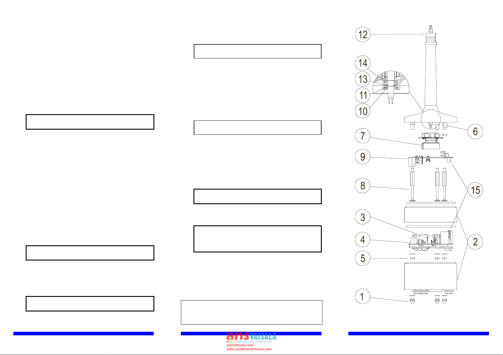
technician. Steps A1 to A15 are for disassembling and steps B1
to B10 are for reassembling. The numbers in parenthesis refer to
Figure 3.
A1. Loosen the set screw (use allen key) and carefully remove
the cup assembly.
CAUTION Be careful with the connector pins, do
not bend them.
A2. Loosen the hex nut of the green MIL-connector at the
bottom of the sensor body (use 22 mm tool).
A3. Loosen the three capnuts (1) at the bottom of the sensor
body (use 7 mm tool).
A4. Remove the body cover and the O-rings (2).
A5. Release the connector (3) of two white wires from the
power supply board (4).
A6. Loosen the three nuts (5) at the bottom of the power
supply board (4) and remove it (use 7 mm tool).
A7. Loosen the shaft heating foil (6) (use pliers).
A8. Loosen the set screw of the rotating transformer assembly
(7) (use allen key).
A9. Loosen the spacer screws (8) (use 6 mm tool).
A10. Remove the sensor board (9) together with the rotating
transformer assembly (7).
CAUTION Handle the rotating transformer
carefully, do not drop or hit.
A11. Remove the retaining ring (10) (use narrow-pointed pliers)
and the bushing (11) from the shaft tunnel.
A12. Remove the upper bearing (12) after pulling out the
shaft.
CAUTION Handle the shaft carefully, do not drop
or hit.
A13. Remove the retaining ring (13) at the shaft.
A14. Remove the lower bearing (14).
For reassembling the sensor:
B1. Install the bearings in reverse order.
NOTE Be careful when assembling the
bearings.
B2. The rotating transformer assembly (7) is reinstalled
together with the sensor board (9). Its (7) set screw is not
fastened until in step B7, when the power supply board
has been reinstalled and the gap adjusted.
B3. In assembling, push the transformer (7) as far up as
possible towards the shaft tunnel.
B4. Reassemble the spacer screws (8), the power supply board
(4) and tighten the nuts (5).
NOTE Make sure the four pin connector (15)
installs properly.
B5. For adjusting the gap, place a 1.2 mm feeler gauge
between ferrite coils (parts 4 and 7) (preferably use 30
mm wide feeler gauge).
B6. Place a screwdriver tip into the slot between the top end
of rotating transformer assembly (7) and the shaft tunnel,
and pry until the air gap between ferrite coils is 1.2 mm
(0.047") (use feeler gauge for measuring).
CAUTION The ferrite coils are breakable, do not
try to adjust the gap by prising them.
B7. When the gap is right, fasten the set screw of the rotating
transformer assembly(7).
CAUTION Make sure the rotating transformer
assembly rotates freely without
touching the lower part at any rotary
position of the shaft.
B8. Reconnect the shaft heating foil (6) and the connector of
two white wires (3).
B9. Reassemble the body cover (2) with new O-rings.
B10. Tighten the three capnuts (1) and the connector nut.
B11. Install the cup assembly as instructed in mechanical section.
Spare parts: Order number:
Cup assembly for WAA252 WA35066
Set of bearings and gasket 16644WA
0602-001
Figure 3 WAA252 Assembly