VAMP Ltd Arc protection system
Operation and configuration instructions
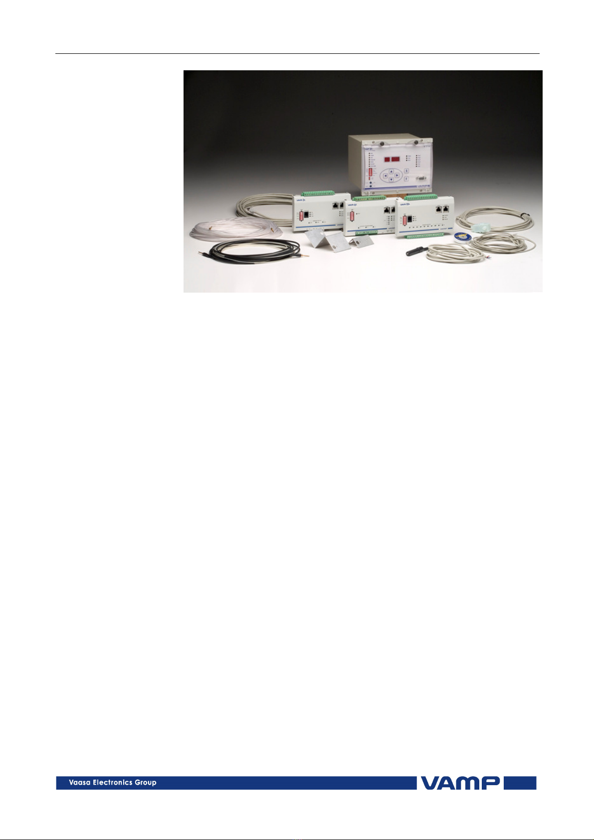
VAMP 221
VM221.EN013 VAMP 24h support phone : +358 0)20 753 3264
Table of Contents
1. General ...................................................................................4
1.1. VAMP 221 arc protection system components .............4
1.1.1. Central unit VAMP 221..............................................6
1.1.2. I/O units VAM 10L, VAM 4C, VAM 3L and VAM
3LX ................................................................................7
1.1.3. Arc sensors VA 1 DA, VA 1 EH, ARC-SLx and VA 1
DP .................................................................................8
1.1.4. Other system components.....................................12
1.2. Operational safety............................................................13
2. User interface .......................................................................14
2.1. Front panel of the central unit VAMP 221 .....................14
2.1.1. Display and status indications ...............................15
2.1.2. Buttons and programming switches.....................16
2.1.3. Moving in menus......................................................17
2.2. I/O unit front panels ..........................................................18
2.2.1. VAM 10L - front panel .............................................19
2.2.2. I/O unit VAM 3L - front plate ..................................20
2.2.3. I/O unit VAM 3LX - front plate................................21
2.2.4. I/O unit VAM 4C - front plate.................................22
2.2.5. Multiplying relay VAR 4CE – front plate................23
2.2.6. Multiplying relay VAMP 4R - front plate................24
. VAMP 221 arc protection system operation and
troubleshooting..........................................................................25
3.1. System status indications .................................................25
3.1.1. Arc fault.....................................................................26
3.1.2. Overcurrent alarm...................................................27
3.1.3. Self-supervision alarm..............................................29
3.1.4. Fault codes ...............................................................30
3.2. Using programming switches ..........................................36
3.2.1. Central unit’s programming switches...................37
3.2.2. Programming switches - I/O units..........................38
3.3. Adjusting the overcurrent setting ...................................41
3.4. Configuration of the arc protection system .................43
3.4.1. Checking system configuration ............................45
4. System commissioning ........................................................46
4.1. Testing - general................................................................46
4.2. Performing the testing ......................................................47
4.3. Periodic commissioning ...................................................47