Vanguard Instruments Company CBCT User manual

CBCTTM
CIRCUIT BREAKER COIL TESTER
USER’S MANUAL
Vanguard Instruments Company, Inc.
1520 S. Hellman Ave.
Ontario, California 91761, USA
TEL: (909) 923-9390
FAX: (909) 923-9391
August 2010
Revision 1

CBCT USER’S MANUAL REV 1
i
SAFETY SUMMARY
FOLLOW EXACT OPERATING PROCEDURES
Any deviation from the procedures described in this User’s Manual may create one or more
safety hazards, may damage the CBCT, or cause errors in the test results. Vanguard Instruments
Company, Inc. assumes no liability for unsafe or improper use of the CBCT.
All safety precautions provided in this manual must be observed during all phases of testing
including test preparation, test lead connection, actual testing, and test lead disconnection.
SAFETY WARNING AND CAUTIONS
The CBCT shall be used only by trained operators. All devices under test shall be off-line and
fully isolated.
DO NOT MODIFY TEST EQUIPMENT
To avoid the risk of introducing additional or unknown hazards, do not install substitute parts or
perform any unauthorized modification to any CBCT test unit. To ensure that all designed safety
features are maintained, it is highly recommended that repairs be performed only by Vanguard
Instruments Company factory personnel or by an authorized repair service provider.
Unauthorized modifications can cause safety hazards and will void the manufacturer’s
warranty.
WARNING
Do not remove test leads during a test. Failure to heed this warning can result in lethal
electrical shock to personnel and damage to the equipment.

REV 1 CBCT USER’S MANUAL
ii
TABLE OF CONTENTS
CONVENTIONS USED IN THIS DOCUMENT ..................................................................................... 1
1.0 INTRODUCTION.................................................................................................................... 2
1.1 General Description and Features ................................................................................... 2
1.2 Technical Specifications ................................................................................................... 3
1.3 CBCT Controls and Indicators .......................................................................................... 4
2.0 OPERATING PROCEDURES ................................................................................................... 6
2.1 CBCT Cable Connections .................................................................................................. 6
2.2 Setting the Output Voltage.............................................................................................. 8
2.3 CBCT Timer Start Input .................................................................................................... 9
2.4 CBCT Timer Stop Input ................................................................................................... 10
2.5 CBCT Timer Display ........................................................................................................ 10
LIST OF FIGURES
Figure 1. CBCT Controls and Indicators........................................................................................... 4
Figure 2. CBCT Constant Output to CB Control Circuits.................................................................. 6
Figure 3. Direct Connection from CBCT Pulse Output to CB Trip Coil ............................................ 7
Figure 4. Direct Connection from CBCT Pulse Output to CB Close Coil.......................................... 7
Figure 5. Typical CBCT Timer Connection ....................................................................................... 9
LIST OF TABLES
Table 1. CBCT Technical Specifications ........................................................................................... 3
Table 2. Functional Descriptions of CBCT Controls and Indicators................................................. 5

CBCT USER’S MANUAL REV 1
1
CONVENTIONS USED IN THIS DOCUMENT
This document uses the following conventions:
•A key, switch, or knob on the CBCT is indicated as [KEY], [SWITCH], and [KNOB].
•Menu names are referenced as “MENU NAME”
•CBCT LCD screen output is shown as:
•Warning messages are indicated as:
WARNING
Warning message
•Important notes are indicated as:
NOTE
Note details
MAIN MENU
<RUN TEST>

REV 1 CBCT USER’S MANUAL
2
1.0 INTRODUCTION
1.1 General Description and Features
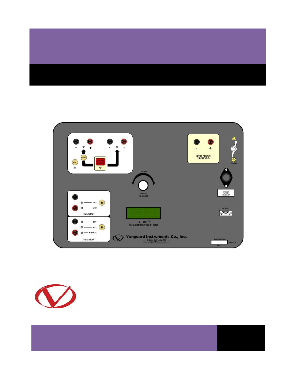
The Vanguard Circuit Breaker Coil Tester (CBCT) is a variable voltage DC power supply designed
specifically to test substation circuit-breaker Open and Close coils. The CBCT uses the
substation’s DC power supply to electronically generate a programmable output voltage from
5% to 95% of the source voltage. The CBCT can maintain up to an 80A test current while
maintaining 2% or better voltage regulation during the circuit breaker coil operation. The CBCT
provides a safe and convenient method for testing minimum operating voltages of Open and
Close coils.
The CBCT provides one pulse and one continuous DC output. The unit’s built-in short-circuit
protection feature protects the coil under test if the current exceeds 80 amperes or if the
current drawing duration is more than 500 milli-seconds. A general purpose single channel
timer is also available for checking circuit breaker operating time or for any other timing
application.
Input Voltage
The CBCT’s input voltage range is from 20 to 300 Vdc. The input circuit is also protected from a
reversed polarity connection.
Output Voltage
The output voltage is programmable from 5% to 95% of the input voltage and is set using the
dial on the front panel. Output voltage regulation is better than 2% under load. Two DC outputs
are available on the CBCT. The continuous DC output is capable of sourcing current up to 40
amperes. The pulse DC output is capable of sourcing up to 80 amperes for up to 500 milli-
seconds. Both outputs are protected against short-circuit conditions if the test current exceeds
80 amperes or if the drawing duration is more than 500 milli-seconds.
CBCT Status Display
The CBCT features a back-lit LCD screen (20 characters by 4 lines) that is viewable in both bright
sunlight and low-light levels. The input and output voltages are displayed on the screen during
testing. If a power supply fault condition occurs, a red “FAULT” LED light is illuminated on the
front panel and a corresponding message is displayed on the LCD screen.
CBCT Timer
The built-in, single channel timer can be used to verify circuit-breaker timing parameters or for
any timing application. The timing range is from 0.000 to 999.000 seconds with an accuracy of
0.1 milli-seconds. The timing results are displayed in both milli-seconds and cycles. The timer
can be started by circuit-breaker coil initiation or can be triggered by the dry or wet contact
input. The timer can be stopped by either the dry or wet contact input.

CBCT USER’S MANUAL REV 1
3
1.2 Technical Specifications
Table 1. CBCT Technical Specifications
TYPE Programmable DC Power Supply
PHYSICAL SPECIFICATIONS 19”W x 7”H x 15”D, (48 cm x 17 cm x 38 cm); Weight: 25 lbs (11.3 kg)
INPUT VOLTAGE 20 – 300 Vdc, 20A fuse
OUTPUT VOLTAGE 5% – 95% of input voltage with 2% regulation at max current (up to 80A)
OUTPUT VOLTAGE CHANNELS One continuous and one pulse DC output
OUTPUT VOLTAGE
PROTECTION
Shutdown if current exceeds 80A or if current drawing time exceeds 500
ms @ 80A
VOLT METER RANGE Input/output meters, 0 – 300 Vdc; Accuracy: 1% of reading, ±0.2V
TIMER DISPLAY RANGE 0.0000 – 999.999 seconds; Accuracy: 0.1 ms, ±1 digit
TIMER START INPUT Internal (coil initiation), wet-contact input (10 c 240 Vac/dc), or dry-contact
input (1 – 200 ohms)
TIMER STOP INPUT Wet-contact (10 – 240 Vac/dc) or dry-contact (1 – 200 ohms)
DISPLAY Back-lit LCD screen (20 characters by 4 lines); viewable in both bright
sunlight and low-light levels
SAFETY Designed to meet UL 6101A-1 and CAN/CSA C22.2 No 1010.1-92
standards
ENVIRONMENT Operating: -10°C to 50°C (+15°F to +122°F); Storage: -30°C to70°C (-22°F
to +158°F)
CABLES Three 6-foot (#10 AWG) DC cable sets, Two 10-foot timer cable sets, One
ground cable, one cable bag
OPTIONS Transportation case
WARRANTY One year on parts and labor
NOTE
The above specifications are valid at nominal operating voltage and at a
temperature of 25°C (77°F). Specifications may change without prior notice.

REV 1 CBCT USER’S MANUAL
4
1.3 CBCT Controls and Indicators
The CBCT’s controls and indicators are shown in Figure 1 below. A leader line with an index
number points to each control and indicator, which is cross-referenced to a functional
description in Table 2. The table describes the function of each item on the control panel. The
purpose of the controls and indicators may seem obvious, but users should become familiar
with them before using the CBCT. Accidental misuse of the controls will usually cause no serious
harm. Users should also be familiar with the safety summary found on the front page of this
User’s Manual.
Figure 1. CBCT Controls and Indicators

CBCT USER’S MANUAL REV 1
5
Table 2. Functional Descriptions of CBCT Controls and Indicators
Item
Number Panel Markings Functional Description
1
Pulse output voltage. Constant output has to be on first. Press PULSE switch to
output voltage. Output voltage is turned on for 1 second. LED indicator is lit
when output is on.
2 OUTPUT
ENABLE
Use this key to turn on the constant output voltage.
3 Constant output voltage. Use [OUTPUT ENABLE] key to turn on or off.
Output is enabled when LED is lit.
4
CHANGE
“PUSH”
TO SELECT
Control knob. Turn to change, press to select.
5 INPUT POWER
(24-240 VDC)
DC voltage input (20-240 VDC).
6 Fuse holder. Use 200 Vdc/25A Littlefuse® P/N KLKR25.
7 GROUND Ground stud. Ground this terminal to sub-station ground.
8 RS-232C RS-232C PC interface for firmware upgrade and diagnostics.
9 Back-lit LCD screen (20 characters by 4 lines), viewable in bright light and low-
light conditions.
10 Timer Start mode selection switch.
11 Timer Stop mode selection switch.
12 Timer Start inputs.
13 Timer Stop inputs.
14
Fault indicator LED is lit when one of the following conditions occurs:
•Coil current exceeds 80A
•Output voltage regulation exceeds 2% at full load
•Coil energization duration is longer than 500ms
15 RESET Reset fault mode.
16 PULSE Enable Pulse output voltage. Press this switch to output DC voltage at the Pulse
voltage terminals for 1 second.

REV 1 CBCT USER’S MANUAL
6
2.0 OPERATING PROCEDURES
2.1 CBCT Cable Connections
Typical CBCT DC control connection diagrams are shown below. Figure 2 illustrates the CBCT
“Constant Output” connection to the circuit breaker control circuit. Figure 3 and Figure 4
illustrate the CBCT “Pulse Output” connection to the circuit breaker Trip and Close coil.
WARNING
Always connect the CBCT ground stud to the sub-station ground.
Figure 2. CBCT Constant Output to CB Control Circuits

CBCT USER’S MANUAL REV 1
7
Figure 3. Direct Connection from CBCT Pulse Output to CB Trip Coil
Figure 4. Direct Connection from CBCT Pulse Output to CB Close Coil

REV 1 CBCT USER’S MANUAL
8
2.2 Setting the Output Voltage
Follow the steps below to set the output voltage:
a. Turn on the unit and start from the “MAIN MENU”:
Press the [CONTROL KNOB] to start the test.
b. The following screen will be displayed:
The input DC voltage is displayed as ‘INPUT VTG: xxx.0’. In the above example, the input
voltage is 124.0. The output voltage is 0.0 since it is not enabled.
Press the [OUTPUT ENABLE] switch.
c. The output voltage will be displayed on the LCD as shown below:
Output voltage is automatically set for 70% of the input voltage. The constant output
voltage indicator will be lit.
Turn the [CONTROL KNOB] to adjust the output voltage.
If the ‘Constant’ output connection is being used, the circuit breaker control circuit
voltage is powered with the voltage displayed on the CBCT screen. The circuit breaker is
now ready to be operated by the control switches.
If the ‘Pulse’ output connection is being used, press the [PULSE] switch to output
voltage to the coil.
INPUT VTG: 124.0
OUTPUT VTG: 86.8
TIME: 0.0mS
Status: *READY*
INPUT VTG: 124.0
OUTPUT VTG: 0.0
TIME: 0.0mS
Status: *READY*
MAIN MENU
<RUN TEST>

CBCT USER’S MANUAL REV 1
9
2.3 CBCT Timer Start Input
Timer Start Input mode can be selected only when the “Main Menu” is being displayed. Select
the Timer Start input mode by pressing the [Arrow] key. The LED will be lit next to the label for
the currently selected mode. The CBCT timer can be started in three selectable modes: internal,
wet input, and dry input. Each mode is described below:
•Internal Mode
In this mode, the timer will start when the [PULSE] switch is pressed. The CBCT will
output the preset voltage to the Pulse output terminals and start the timer.
•Dry Contact Mode
In this mode, the timer will look for a change in the Start input terminals after the
[PULSE] switch is pressed. The CBCT will output a DC voltage to the Start input
terminals to detect the dry contact status.
•Wet Contact Mode
In this mode, the timer will look for a change in the Start input terminals after the
[PULSE] switch is pressed. In this mode, the input will look for a change in voltage or
no-voltage condition to start the timer. A voltage from 24 Vdc to 300 Vdc is considered
as ‘Voltage Present’.
Figure 5. Typical CBCT Timer Connection
(Internal Start, Dry Contact Stop)

REV 1 CBCT USER’S MANUAL
10
2.4 CBCT Timer Stop Input
Timer Start Input mode can be selected only when the “Main Menu” is being displayed. Select
the Timer Stop Input mode by pressing the [ARROW] key. The LED will be lit next to the label
for the currently selected mode. The CBCT timer can be stopped in two selectable modes
described below:
•Dry Contact Mode
In this mode, the timer will look for a change in the Stop Input terminals to stop the
timer. The CBCT will output a DC voltage to the Stop Input terminals to detect the dry
contact status.
•Wet Contact Mode
In this mode, the timer will look for a change in the Stop Input terminals to stop the
timer. Under the wet contact mode, the input is looking for a change in voltage or no-
voltage condition to stop the timer. A voltage from 24 Vdc to 300 Vdc is considered as
‘Voltage Present’.
2.5 CBCT Timer Display
The CBCT displays the timer result in milliseconds and seconds on the LCD. Typical timer test
results are shown below:
INPUT VTG: 48.5
OUTPUT VTG: 33.7
TIME: 197.3mS
Status: *READY*

1520 S. Hellman Ave •Ontario, CA 91761 •USA
Phone: 909-923-9390 •Fax: 909-923-9391
www.vanguard-instruments.com
Copyright 2009 by Vanguard Instruments Company, Inc.
CBCT User’s Manual •Revision 1.0 •August 18, 2010 •TA
Table of contents
Other Vanguard Instruments Company Test Equipment manuals
Popular Test Equipment manuals by other brands

Agilent Technologies
Agilent Technologies 8960 Series 10 Reference manual

Eaton
Eaton SEFELEC 5 Series user manual

Keysight Technologies
Keysight Technologies N7015A Quick Start and Accessories Guide

EKO Instruments
EKO Instruments MP-01 quick start guide

Klein Tools
Klein Tools NCVT-1XT instructions

I S TECHNOLOGY SOLUTIONS
I S TECHNOLOGY SOLUTIONS BRAKE PRO S-4027 operating manual