Vanguard Instruments Company SGT-600 User manual

http://www.51082245.com
SGT-600
SAFETY GROUND TESTER
USER’S MANUAL
Vanguard Instruments Company, Inc.
1520 S. Hellman Ave.
Ontario, California 91761, USA
TEL: (909) 923-9390
FAX: (909) 923-9391
April 2015
Revision 1.0

http://www.51082245.com
SGT-600 USER’S MANUAL REV 1.0
i
SAFETY SUMMARY
FOLLOW EXACT OPERATING PROCEDURES
Any deviation from the procedures described in this user’s manual may create one or more safety hazards,
damage the SGT-600, or cause errors in the test results. Vanguard Instruments Co., Inc. assumes no liability for
unsafe or improper use of the SGT-600. The following safety precautions must be observed during all phases of
test setup, test hookups, testing, and test lead disconnection.
SAFETY WARNINGS AND CAUTIONS
The SGT-600 shall be used only by trained operators. All circuit breakers under test shall be off-line and fully
isolated.
SERVICE AND REPAIR
• Do not install substitute parts or perform any unauthorized modification to any SGT-600 test unit.
• Repairs must be performed only by Vanguard Instruments Company factory personnel or by an authorized
repair service provider. Unauthorized modifications can cause safety hazards and will void the manufacturer’s
warranty.
EQUIPMENT RATINGS
IP Rating: The enclosure for the SGT-600 has an IP rating of 32.
Pollution Degree: The SGT-600 has a pollution rating of 2.
Operating Voltage: The SGT-600 is rated for use with an operating voltage of 120V or 240V, auto-ranging ±10% of
selected voltage.
Power Cord: The SGT-600 is supplied with a 16 AWG, 16A power cord with a NEMA 5-15P plug. Replacement cable
shall have the same or better rating and is available through the manufacturer.
VENTILATION REQUIREMENTS
The SGT-600 must be operated with the enclosure lid open.
SAFETY SYMBOLS
Indicates that caution should be exercised
Indicates location of chassis ground terminal
CLEANING
To clean the SGT-600:
• Disconnect all cables and turn the unit off.
• Use a soft, lint-free cloth to wipe all surfaces clean.
• Avoid getting moisture in openings and connectors.
• Don't use any cleaning products or compressed air.

http://www.51082245.com
REV 1 SGT-600 USER’S MANUAL
ii
TABLE OF CONTENTS
CONVENTIONS USED IN THIS DOCUMENT ..................................................................................... 1
1.0 INTRODUCTION.................................................................................................................... 2
1.1 General Description and Features ................................................................................... 2
1.2 SGT-600 Technical Specifications .................................................................................... 4
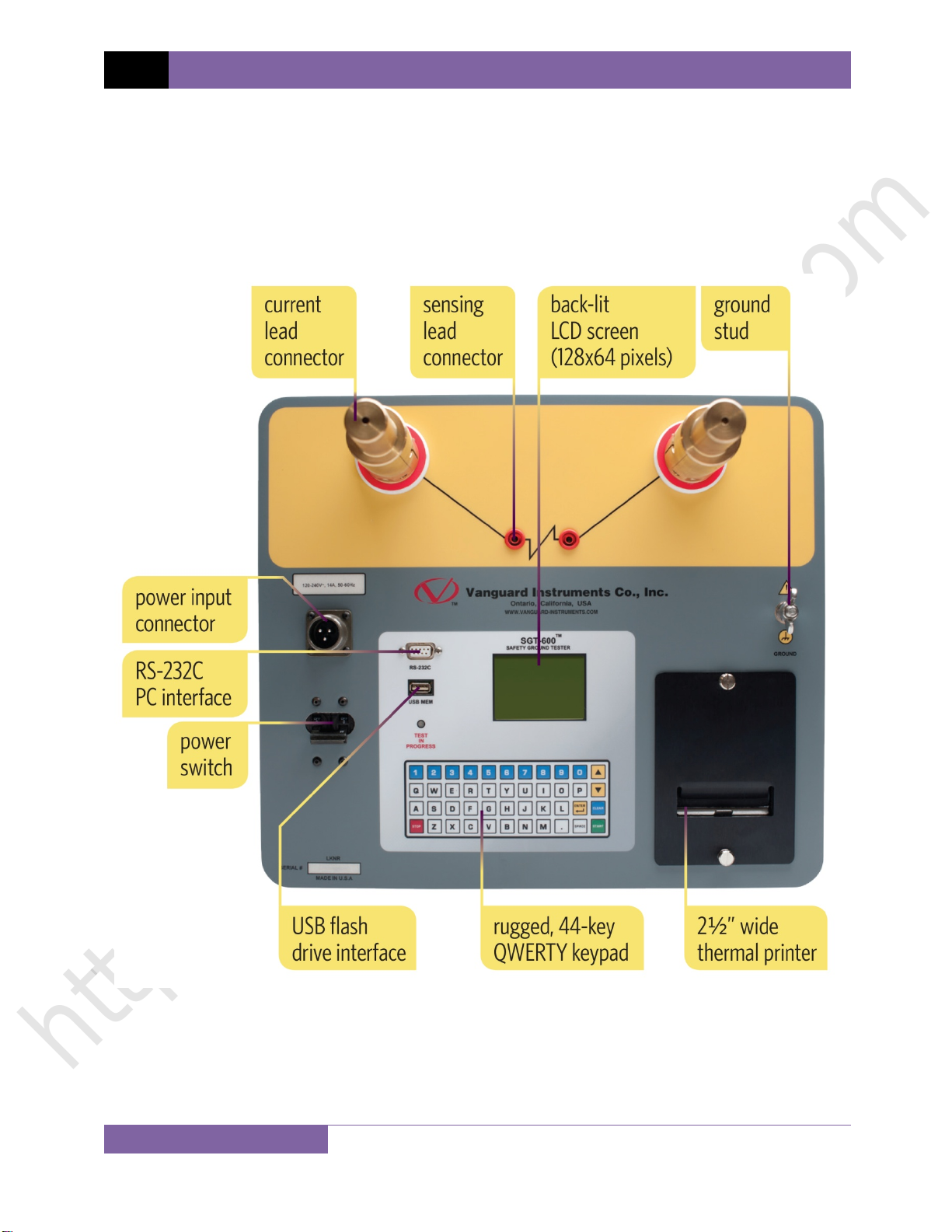
1.3 SGT-600 Controls and Indicators ..................................................................................... 5
2.0 PRE-TEST SETUP ................................................................................................................... 6
2.1 Operating Voltages .......................................................................................................... 6
2.2 LCD Screen Contrast Control............................................................................................ 6
3.0 OPERATING PROCEDURES ................................................................................................... 7
3.1 Connection Diagrams....................................................................................................... 7
3.3 Setting the Interface Language........................................................................................ 9
3.4 Setting the Option to Print the Calibration Expiration Date.......................................... 10
3.5 Testing Procedures ........................................................................................................ 12
3.5.1. Entering Test Record Header Information ............................................................. 12
3.5.2. Performing a Test ................................................................................................... 15
3.5.3. Performing Diagnostic Tests .......................................................................................... 20
3.6 Working With Test Records ........................................................................................... 24
3.6.1. Viewing the Contents of the Working Memory ..................................................... 24
3.6.2. Saving Test Results to a Test Record ...................................................................... 26
3.6.3. Restoring a Test Record From Flash EEPROM........................................................ 28
3.6.4. Restoring a Test Record From a USB Flash Drive ................................................... 32
3.6.5. Copying Test Records to a USB Flash Drive............................................................ 34
3.6.6. Printing the Test Record Directory......................................................................... 37
3.6.7. Erasing Test Records from the Unit's Flash EEPROM............................................. 40
3.6.8. Erasing Test Records from a USB Flash Drive......................................................... 45
4.0 Getting the Latest Firmware, Software, and Manuals....................................................... 48
LIST OF FIGURES
Figure 1. SGT-600 Controls and Indicators ..................................................................................... 5
Figure 2. Typical SGT-600 Connection Diagram.............................................................................. 7
Figure 3. Sample Test Report Printout with Calibration Expiration Date..................................... 11
Figure 4. Sample SGT-600 Test Results Printouts......................................................................... 19
Figure 5. Performing a Diagnostic Test Between Points A and B ................................................. 20
Figure 6. Sample Diagnostic Test Results Printout ....................................................................... 23
Figure 7. Sample Thumb Drive Directory Printout ....................................................................... 39
Figure 8. Sample Internal Test Record Directory Printout............................................................ 39

http://www.51082245.com
REV 1 SGT-600 USER’S MANUAL
1
CONVENTIONS USED IN THIS DOCUMENT
This document uses the following conventions:
•
A key, switch, or knob on the SGT-600 is indicated as
[KEY], [SWITCH], [KNOB]
.
•
Menu names are referenced as “MENU NAME”
• SGT-600 screen output is shown as:
• When instructions are provided, the menu item that should be selected is shown in bold
(option 3 should be selected):
• Warning messages are indicated as:
WARNING
Warning message
• Important notes are indicated as:
NOTE
Note details
1. OPTION 1
2. OPTION 2
3. OPTION 3
4. OPTION 4
5. OPTION 5
1. OPTION 1
2. OPTION 2
3. OPTION 3
4. OPTION 4
5. OPTION 5

http://www.51082245.com
SGT-600 USER’S MANUAL REV 1
2
1.0 INTRODUCTION
1.1 General Description and Features
The SGT-600 is a 600 ampere micro-ohm meter designed for testing utility safety ground cables.
The SGT-600 features microprocessor-controlled highly accurate measuring of very low
resistances ranging from 1 micro-ohm to 450 milliohms. The SGT-600 is field-portable, rugged,
and easily operated by first-time users with a minimum training. It features a 44-key
"QWERTY"-style keypad for entering test parameters and controlling the unit and a back-lit LCD
screen (128 x 64 pixels) for displaying menus, measured resistance values, and related
identifying data. The SGT-600 also features a built-in thermal printer used to print test data on
2.5" wide thermal paper. Operating the unit requires little more than connecting the safety
leads to the SGT-600 terminals, enter the test cable size, cable length, cable temperature, and
the test current. The SGT-600 will measure the cable resistance and compare this reading
against the maximum allowable resistance value (defined by ASTM F2249). The resistance
reading along with the Pass or Fail results can be printed using the built-in thermal printer.
Test current is selectable from 10 to 600 amperes. The SGT-600 can also store 100 test records
in internal FLASH EEPROM memory. Stored resistance measurements and related data can be
recalled at a later time for review and printing and can also be transferred to a USB Flash drive
using the unit's built-in Flash drive port.
Windows®-based analysis software is provided with each unit. The software can be used to
retrieve test records from the unit's internal memory or from a computer hard drive, analyze
test results, and print test results on a desktop printer. Test results can also be exported to PDF,
Excel and XML formats.
The SGT-600 measures the total resistance value of the cable under test and then compares it
to the calculated value to determine the Pass or Fail result. In order to calculate the total
resistance value, the user is first prompted for the cable size, cable length, and cable
temperature. Total resistance (Rm) is calculated in accordance with the ASTM F2249-03
standard using the formula below:
Rm = 1.05 RL + 2Y = 1.05 RL + 320 µΩ*
Where:
Y= Resistance of clamps, ferrule, and portions of the cable inside the ferrule, in milliohms*
L= Cable length in feet (ferrule to ferrule measurement to the nearest inch)
R = Cable resistance, in milliohms/foot
* NOTE: The clamp and ferrule resistance value of 160 µΩis used per the ASTM-F2249-03
standard.

http://www.51082245.com
REV 1 SGT-600 USER’S MANUAL
3
The SGT-600 will calculate the maximum resistance value of the cable under test, measure the
resistance value and compare this value against the limit. The resistance value and a PASS or
FAIL result can be printed on the thermal printer.

http://www.51082245.com
SGT-600 USER’S MANUAL REV 1
4
1.2 SGT-600 Technical Specifications
TYPE Portable Micro-Ohmmeter
PHYSICAL SPECIFICATIONS Dimensions: 16.75”W x 12.5”H x 12” D (42.7 cm x 32 cm x 30.5 cm)
Weight: 19.8 lbs. (8.9 Kg)
INPUT POWER 100 240 Vac, 50/60 Hz
RESISTANCE READING
RANGE 1 micro-ohm to 1000 milliohms
(max 1.5 milliohms @ 600A, 450 milliohms @ 10A, 1000 milliohms @ 1A)
TEST CURRENT RANGE 10A 600A (selectable in 1A steps);
thermally protected DC power supply
ACCURACY 10A 49.9A: 1% ±2 micro-ohms, 50A 600A: 1% ±1 micro-ohm
TEST VOLTAGE 5 Vdc
DISPLAY back-lit LCD screen (128 x 64 pixels)
viewable in bright sunlight and low-light levels
KEYPAD rugged, 44-key "QWERTY"-style membrane keypad
INTERNAL
TEST RECORD STORAGE 100 test records
EXTERNAL
TEST RECORD STORAGE up to 999 test records on external USB flash drive
PC SOFTWARE Windows®-based analysis software is included with purchase price
COMPUTER INTERFACES one RS-232C PC interface, one USB flash drive interface
PRINTER built-in 2.5” wide thermal printer
SAFETY designed to meet IEC 61010 (1995), UL 61010-a, and CAS-C22.2 standards
TEMPERATURE Operating: -10°C to +50°C (+15°F to +122°F)
Storage: -30°C to +70°C (-22°F to +158°F)
HUMIDITY 90% RH @ 40°C (104°F) non-condensing
ALTITUDE 2,000 m (6,562 ft) to full safety specifications
CONNECTION POSTS Two 2”/3” diameter posts
CABLES sensing leads, hand probes, power cord, ground cable
OPTIONS shipping case
WARRANTY one year on parts and labor
NOTE
The above specifications are valid at nominal operating voltage and at a
temperature of 25°C (77°F). Specifications may change without prior notice.

http://www.51082245.com
REV 1 SGT-600 USER’S MANUAL
5
1.3 SGT-600 Controls and Indicators
The SGT-600’s controls and indicators are shown in Figure 1. The purpose of the controls and
indicators may seem obvious, but users should familiarize themselves with them before using
the SGT-600. Accidental misuse of the controls will usually cause no serious harm. Users should
also familiarize themselves with the safety summary information found on the front page of
this User’s Manual.
Figure 1. SGT-600 Controls and Indicators

http://www.51082245.com
SGT-600 USER’S MANUAL REV 1
6
2.0 PRE-TEST SETUP
2.1 Operating Voltages
The SGT-600 operate on voltages between 120-240 Vac, 50/60 Hz.
2.2 LCD Screen Contrast Control
To increase the LCD screen contrast, press and hold the [] key for two seconds. Release the
button when the desired contrast level has been reached.
To decrease the LCD screen contrast, press and hold the [] key for two seconds. Release the
button when the desired contrast level has been reached.
2.3 Safety Ground
Always ground the SGT-600 to the substation ground before connecting cables to the unit.
2.4 Printer Paper
The SGT-600’s built-in thermal printer uses 2.5" wide thermal paper for printing test results. To
maintain the highest print quality and to avoid paper jams, the use of thermal paper supplied
by Vanguard Instruments Company is highly recommended. Additional paper can be ordered
from the following sources:
Vanguard Instruments Co, Inc.
1520 S. Hellman Avenue
Ontario, CA 91761
Tel: 909-923-9390
Fax: 909-923-9391
Part Number: TP3-CS
BG Instrument Co.
13607 E. Trent Avenue
Spokane, WA 99216
Tel: 509-893-9881
Fax: 509-893-9803
Part Number: VIC TP-3 paper

http://www.51082245.com
REV 1 SGT-600 USER’S MANUAL
7
3.0 OPERATING PROCEDURES
3.1 Connection Diagrams
Figure 2. Typical SGT-600 Connection Diagram

http://www.51082245.com
SGT-600 USER’S MANUAL REV 1
8
3.2 Setting the Date and Time
To set the date and time:
a. Start from the “START-UP” menu:
Press the [2] key (SETUP).
b. The following screen will be displayed:
Press the [4] key (SET TIME)
c. The following screen will be displayed:
Type in the date using the keypad. The following screen will be displayed:
Enter the time using the keypad. When the time has been entered, you will be
immediately returned to the “START-UP” menu.
ENTER TIME
HH:MM:SS
ENTER DATE
MM-DD-YY
1. RECORD ID
2. REVIEW RECORD
3. SAVE/RESTORE RECORD
4. set time
5. set language
6. CAL NOTICE ON/OFF
1.RUN TEST
2.SETUP
time: 10:11:12 23°C
date: 04/01/15 73°F

http://www.51082245.com
REV 1 SGT-600 USER’S MANUAL
9
3.3 Setting the Interface Language
Follow the steps below to set the interface language (English):
a. Start from the “START-UP” menu:
Press the [2] key (SETUP).
b. The following screen will be displayed:
Press the [5] key (SET LANGUAGE).
c. The following screen will be displayed:
Select the preferred interface language by pressing the corresponding key on the
keypad ([1], [2], or [3]). The interface language will be set and a confirmation screen
will be displayed as shown below:
Press any key to return to the “START-UP” menu.
ENGLISH SET
1. ENGLISH
2. TURKISH
3. SPANISH
1. RECORD ID
2. REVIEW RECORD
3. SAVE/RESTORE RECORD
4. set time
5. set language
6. CAL NOTICE ON/OFF
1.RUN TEST
2.SETUP
time: 10:11:12 23°C
date: 04/01/15 73°F

http://www.51082245.com
SGT-600 USER’S MANUAL REV 1
10
3.4 Setting the Option to Print the Calibration Expiration Date
The SGT-600 can print the unit's factory calibration expiration date at the bottom of test
reports if desired. Follow the steps below to configure this option:
a. Start from the "START-UP" menu:
Press the [2] key (SETUP).
b. The following screen will be displayed:
Press the [6] key (CAL NOTICE ON/OFF)
c. The following screen will be displayed:
1. Press the [1] key to enable to option. The following screen will be displayed:
The calibration date printing option will be enabled and you will be returned to
the "START-UP" menu. Figure 3 shows a sample test report with the calibration
expiration date printed at the bottom.
CAL DATE PRINTING
ENABLED.
CAL DATE PRINTING:
1. ENABLE
2. DISABLE
1. RECORD ID
2. REVIEW RECORD
3. SAVE/RESTORE RECORD
4. set time
5. set language
6. CAL NOTICE ON/OFF
1.RUN TEST
2.SETUP
time: 10:11:12 23°C
date: 04/01/15 73°F

http://www.51082245.com
REV 1 SGT-600 USER’S MANUAL
11
2. Press the [2] key to disable the option. The following screen will be displayed:
Press any key to return to the "START-UP" menu.
Figure 3. Sample Test Report Printout with Calibration Expiration Date
CAL DATE PRINTING
DISABLED.

http://www.51082245.com
SGT-600 USER’S MANUAL REV 1
12
3.5 Testing Procedures
3.5.1. Entering Test Record Header Information
You can enter the test record header information before performing tests. The record header
includes identifying information such as the company, station, circuit, manufacturer, etc. Once
the header information has been set, it will apply to all subsequent test records. Follow the
steps below to enter the test header information:
a. Start from the “START-UP” menu:
Press the [2] key (SETUP).
b. The following screen will be displayed:
Press the [1] key (RECORD ID).
c. The following screen will be displayed:
Type the company name using the keypad. Press the [ENTER] key when you are done
typing the company name.
COMPANY:
_
↑/↓TO POSITION
"ENTER" TO ACCEPT
1. RECORD ID
2. REVIEW RECORD
3. SAVE/RESTORE RECORD
4. set time
5. set language
6. CAL NOTICE ON/OFF
1.RUN TEST
2.SETUP
time: 10:11:12 23°C
date: 04/01/15 73°F

http://www.51082245.com
REV 1 SGT-600 USER’S MANUAL
13
d. The following screen will be displayed:
Type the location name using the keypad and then press the [ENTER] key.
e. The following screen will be displayed:
Type the manufacturer name using the keypad and then press the [ENTER] key.
f. The following screen will be displayed:
Type the safety ground cable's model information using the keypad and then press the
[ENTER] key.
g. The following screen will be displayed:
Type the safety ground cable's serial number using the keypad and then press the
[ENTER] key.
h. The following screen will be displayed:
SERIAL NUMBER:
_
↑/↓TO POSITION
"ENTER" TO ACCEPT
MODEL:
_
↑/↓TO POSITION
"ENTER" TO ACCEPT
MANUFACTURER:
_
↑/↓TO POSITION
"ENTER" TO ACCEPT
LOCATION:
_
↑/↓TO POSITION
"ENTER" TO ACCEPT

http://www.51082245.com
SGT-600 USER’S MANUAL REV 1
14
Type the safety ground cable's rating using the keypad and then press the [ENTER]
key.
i. The following screen will be displayed:
Type the operator’s name using the keypad and then press the [ENTER] key.
j. The following screen will be displayed:
Type any additional notes regarding the test and then press the [ENTER] key. All
header information will be saved, and you will be returned to the “START-UP” menu.
NOTE:
_
↑/↓TO POSITION
"ENTER" TO ACCEPT
OPERATOR:
_
↑/↓TO POSITION
"ENTER" TO ACCEPT
RATING:
_
↑/↓TO POSITION
"ENTER" TO ACCEPT

http://www.51082245.com
REV 1 SGT-600 USER’S MANUAL
15
3.5.2. Performing a Test
Follow the steps below to perform a test:
a. Start from the "START-UP" menu:
Press the [1] key (RUN TEST).
b. The following screen will be displayed:
Press the [1] key (FULL CABLE TEST).
c. The following screen will be displayed:
Select the test current by pressing the corresponding key on the keypad. Press the [8]
key if you would like to enter a custom test current value. You will be able to enter a
test current value between 10A and 600A.
d. The following screen will be displayed:
Select the cable gauge by pressing the corresponding key on the keypad.
CABLE GAUGE
1. AWG 2
2. AWG 1/0
3. AWG 2/0
4. AWG 4/0
SELECT TEST CURRENT
1. 10A 2. 25A
3. 50A 4. 100A
5. 200A 6. 400A
7. 600A
8. CUSTOM
1. FULL CABLE TEST
2. DIAGNOSTIC PROBE
1.RUN TEST
2.SETUP
time: 10:11:12 23°C
date: 04/01/15 73°F

http://www.51082245.com
SGT-600 USER’S MANUAL REV 1
16
e. The following screen will be displayed:
You can adjust the cable length by 3" (0.0762 m) increments. Press the []key to
increase the cable length or the []key to decrease the cable length. The screen will
be updated showing the new length. Press the [ENTER] key when the correct length is
displayed.
f. The following screen will be displayed:
You can adjust the cable temperature by 0.5°C increments. Press the []key to
increase the cable temperature or the []key to decrease the cable temperature. Press
the [ENTER] key when the correct cable temperature is displayed.
g. A summary of the test parameters will be displayed as shown below:
Press the [START] key to run the test.
TEST PARAMETERS
CURRENT: 10 AMPS
GAUGE: AWG 2
LENGTH: 33.00 Ft
TEMP: 25.0°C
"START" TO RUN TEST
CABLE TEMP:
25.0°C 77.0°F
↑/↓TO adjust length
"ENTER" TO ACCEPT
CABLE LENGTH:
33.00 Ft 10.058 M
(33'0")
↑/↓TO adjust length
"ENTER" TO ACCEPT

http://www.51082245.com
REV 1 SGT-600 USER’S MANUAL
17
h. The unit will start ramping the current till the selected current is reached. The screen
will be updated as shown below:
Once the test current has been reached, the SGT-600 will measure the resistance and
update the screen as shown below:
The unit will then ramp down the current to zero and display the final test results as
shown below:
If the cable under test passed the test, "[P]" will be displayed as shown in the example
above. If it failed, "[F]" will be displayed next to the test results.
Press any key to continue.
i. The following screen will be displayed:
Press the [1] key to print the test results. Figure 4 shows sample test results printouts.
PRINT TEST RESULTS?
1. YES
2. NO
MEASURING
4.667 mΩ [P]
10.03A
TEST IN PROGRESS...
MEASURING
4.668 mΩ
10.03A
TEST IN PROGRESS...
RAMPING CURRENT
2.10A 21%
TEST IN PROGRESS...
Table of contents
Other Vanguard Instruments Company Test Equipment manuals