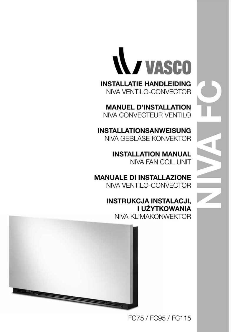
Vasco NIVA FC75 User manual

GEBRUIKERS HANDLEIDING
NIVA VENTILO-CONVECTOR
MANUEL D’UTILISATION
NIVA VENTILO CONVECTEUR
GEBRAUCHSANWEISUNG
NIVA GEBLÄSEKONVEKTOR
USER MANUAL
NIVA FAN COIL UNIT
MANUALE D’USO
NIVA VENTIL CONVETTORE
INSTRUKCJA INSTALACJI,
I UŻYTKOWANIA
NIVA KLIMAKONWEKTOR
FC75 / FC95 / FC115
NIVA FC

NL
FR
DE
EN
IT
PL
CONTENTS 01
CONTENTS
1 GENERAL
Electronic panel 2
Display 2
Key function 3
General On Switch 3
Activation 3
Heating/cooling operation modes setting 4
Stand-by 4
Temperature selection 4
Automatic operation 5
Silent operation 5
Night-time operation 5
Operation at maximum ventilation speed 5
Key Lock 6
Reduce brightness to minimum 6
Deactivation 6
Room temperature probe regulation offset 6
Switching off for long periods 7
Error signals 7
2 MAINTENANCE
External cleaning 8
Air suction lter cleaning 8
Cleaning the lters 9
Suggestions for power saving 9
3 TROUBLESHOOTING
Troubleshooting 10
Troubleshooting table 11
4 WARRANTY CONDITIONS
Warranty conditions 12

02 CONFORMITY / SYMBOLS / CONTENTS
This unit complies with European directives:
• Low voltage 2014/35/EU
• Electro-magnetic compatibility 2014/30/EU
The pictograms in the next chapter provide the necessary information for
correct, safe use of the machine in a rapid, unmistakable way.
SAFETY PICTOGRAMS
Generic danger
Signals to the personnel that the operation described could cause
physical injury if not performed according to the safety rules.
Danger of high voltage
Signals to the personnel that the operation described could cause
electrocution if not performed according to the safety rules.
Danger due to heat
Signals to the personnel that the operation described could cause burns
if not performed according to the safety rules.
Prohibition
Refers to prohibited actions.
CONFORMITY
SYMBOLS

NL
FR
DE
EN
IT
PL
These controls make room temperature adjustment (with offset settable from
the keyboard) completely autonomous through the AUTO, SILENT, NIGHT and
MAX programmes by means of a probe located in the lower part of the device,
ensuring anti-freeze safety even when set to stand-by.
The control panel has a memory, so settings will not be lost if the appliance is
switched off or in the power supply is cut.
After 20 seconds from the last action the panel brightness will be reduced for
improved night-time comfort, and the room temperature will appear on the
display. Press any key to restore maximum brightness.
The 10 kΩ water temperature probe positioned in the device battery
regulations the minimum level when heating (28°C) and the maximum level
when cooling (20°C).
Any statuses and alarms are also shown on the display by using 8 specific
symbols:
Automatic operation Heating on
Silent operation Cooling on
Maximum ventilation
speed
Alarm indicator
(solid light)
Night-time operation Panel off indicator
1 GENERAL
ELECTRONIC PANEL
DISPLAY
A Display
B Keys
NL
FR
DE
EN
IT
PL
ELECTRONIC PANEL / DISPLAY 03

The various functions are set using 8 backlit keys:
Temp +
is for increasing the set
temperature
Night-time operation:
limits ventilation speed
to a contained level and
the set temperature is
adjusted automatically.
Temp -
is for decreasing the
set temperature
Maximum speed
operation: Allows for
the maximum ventilation
speed to be set
Heating / Cooling: for
changing the operation
mode between heating
and cooling
ON/Stand-By: for
activating the device or
for putting it in stand-by.
Sets the regulation
ventilation speed
between a minimum
and maximum value to
an entirely automatic
mode
Silent: limits ventilation
speed to a more
contained value
In order to manage the device via the control panel, this must be connected to
the mains electricity.
If a general switch is installed on the power line, this must also be switched on.
- Turn the device on by activating the general switch
To activate the device
Key Operation Display
Press the ON Stand-by key From off to on
Select one of the 4 operating
modes by pressing the relative
key.
KEY FUNCTION
GENERAL ON SWITCH
ACTIVATION
04 KEY FUNCTION / GENERAL ON SWITCH / ACTIVATION

HEATING/COOLING
OPERATION
MODES SETTING
STAND BY
Key Operation Display
Keep the Heating / Cooling key pressed for approx.
2 seconds to change the mode between heating
and cooling, which is indicated by the 2 symbols
that appear if heating or cooling is active.
When heating, the symbol displays when the set
point is higher than ambient temperature, both are
off when the set point is lower.
When cooling, the symbol displays when the set
point is lower than ambient temperature, both are
off when the set point is higher.
One of the two symbols flashing means that the water temperature (hot or
cold) is not sufficient, and stops the fan until the temperature reaches a level
suitable for reaching the required temperature.
If after switching the power on the board detects the H2 probe, start-up
occurs in normal conditions with the minimum and maximum thresholds.
The board also has a function when there is no H2 probe, in such cases the
fan stop thresholds are ignored.
Key Operation Display
Press and hold the ON Stand-By key for approx.
2 seconds. No illuminated signals on the display
at all means that the system is in stand-by (no
operation).
Off
When the control is in this operating mode, anti freezing is in any case
guaranteed. If the ambient temperature drops below 5°C, the solenoid valves
on the hot water output and the boiler are opened.
Key Operation Display
Set the required room temperature using the two
increase/decrease keys to set the temperature
value on the 3-digit display. 20.5
The adjustment range is from 16 to 28°C in intervals of 0.5°C, but out-of-
range values are also accepted, from 5°C to 40°C (unless in auto mode).
Only set these values for brief periods, and then set a intermediate value.
The controller is very precise - set it to the required value and wait for the
controller to regulate itself according to the actual room temperature detected.
TEMPERATURE
SELECTION
NL
FR
DE
EN
IT
PL
HEATING/COOLING OPERATION MODES SETTING / STAND BY / TEMPERATURE SELECTION 05

06 AUTOMATIC OPERATION / SILENT OPERATION / NIGHT-TIME OPERATION
AUTOMATIC
OPERATION
SILENT OPERATION
NIGHT-TIME
OPERATION
OPERATION
AT MAXIMUM
VENTILATION SPEED
Key Operation Display
Press and hold the AUTO key. The function being
activated is indicated by the relevant symbol
appearing on the display.
Ventilation speed adjustment is carried out automatically between the
minimum and maximum values, according to the distance of the actual room
temperature from the set point, according to a PI-type algorithm.
Key Operation Display
Press and hold the Silent key. The function being
activated is indicated by the relevant symbol
appearing on the display.
Ventilation speed is limited to a contained maximum value.
Key Operation Display
Press and hold the Night-time operation key. The
function being activated is indicated by the relevant
symbol appearing on the display.
By selecting this mode, ventilation speed is limited to a very contained level
and the set temperature is adjusted automatically, as follows:
- decreases by 1°C after one hour and by another degree after two hours in
heating mode;
- increases by 1°C after one hour and by another degree after two hours in
cooling mode;
Key Operation Display
Press and hold the Max Operation key. The function
being activated is indicated by the relevant symbol
appearing on the display.
In this operation mode, the maximum possible power level is activated
whether heating or cooling.
Once the desired room temperature is reached, we recommend selecting one
of the other 3 operation modes for increased comfort and sound levels.

KEY LOCK / REDUCE BRIGHTNESS / DEACTIVATION / ROOM TEMPERATURE REGULATION 07
KEY LOCK
Key Operation Display
By pressing both the + and - keys for 3 seconds, all
keys are locked locally, and this is indicated by "bL"
appearing on the display.
All actions are disabled to the user and whenever
any key is pressed, "LOC" will appear. To unlock
the keys, repeat the sequence.
bL
After 20 seconds from the last action, the panel brightness will be reduced for
improved night-time comfort, and the room temperature will appear on the
display.
If this brightness is still disturbing, the display can be switched off completely.
Key Operation Display
With the display off, press and hold the + key for 5
seconds until "01" is displayed.
Use the - key to change the value to 00 and wait 20
seconds to check the setting has been accepted.
00
As the detection probe is towards the bottom of the device, the temperature
detected may at times differ from the actual room temperature. By using this
function, the value displayed can be adjusted in a range from -9/+12 K in
intervals of 0.1°C. Use this adjustment with care, and only after having actually
detected a discrepancy compared with the actual room temperature using a
reliable device!
Key Operation Display
With the display off, press and hold the - key
for 5 seconds to access the menu which allows
adjustment (using the + and - keys) of the AIR probe
offset displayed, from -9 to +12 K in 0.1 K intervals.
After 20 seconds from the last action, the panel
switches off and the setting is stored.
00.0
REDUCE BRIGHTNESS
TO MINIMUM
ROOM
TEMPERATURE
PROBE
REGULATION OFFSET
NL
FR
DE
EN
IT
PL

08 SWITCHING OFF FOR LONG PERIODS / ERROR SIGNALS
SWITCHING OFF FOR
LONG PERIODS
ERROR SIGNALS
When switching off for a season or for holidays, proceed as follows:
- Deactivate the device
- Turn the general unit switch to off.
The antifreeze function is not active.
Error Display
Faulty room temperature (AIR) probe. E1
Problem with fan motor (e.g. blockage caused by foreign
objects, faulty rotation sensor). E2
Water temperature probe fault for 2-tube versions (H2).
In this case, ensure that the probe installed is 10 kΩ. E3
Engaging of grille microswitch S1 due to filter cleaning
operation Gr
EXTERNAL
CLEANING
AIR SUCTION
FILTER CLEANING

EXTERNAL CLEANING / AIR SUCTION FILTER CLEANING 09
EXTERNAL
CLEANING
Disconnect the unit from the power supply before each cleaning and
maintenance intervention by setting the main power supply switch to off.
Wait for the components to cool down in order to avoid any burns.
Do not use abrasive sponges or abrasive or corrosive detergents as you might
damage the painted surfaces.
When necessary, clean the external surfaces of the fan coil with a soft damp
cloth.
Clean the air filter after a period of continuous use and according to the
concentration of impurities in the air; or when you wish to start-up the
appliance after a period of inactivity, proceed as described.
REMOVAL OF FILTERING CELLS
- extract the filter by pulling outwards horizontally.
2 MAINTENANCE
AIR SUCTION
FILTER CLEANING
filter extraction
AB
C
D
NL
FR
DE
EN
IT
PL

10 CLEANING THE FILTERS / SUGGESTIONS FOR POWER SAVING
Afilter
Blower edge
Cfilter housing
- Remove dust from the filter with a vacuum cleaner
- Wash the filter under running water without using detergents or solvents,
and leave to dry.
- Replace the filter on the fan coil, paying particular attention to insert the
lower edge in its housing.
Do not use the device without the mesh filter.
The device is fitted with a safety switch that prevents fan operation without the
mobile panel in place.
After filter cleaning, check that the panel is properly mounted.
CLEANING
THE FILTERS
- Ensure filters are constantly clean;
- Keep doors and windows closed as far as possible in rooms to be
conditioned;
- In summer, limit direct sunlight as far as possible in rooms to be conditioned
(with curtains, shutters, etc.).
SUGGESTIONS
FOR POWER SAVING
TROUBLESHOOTING
ABB
C

3 TROUBLESHOOTING
TROUBLESHOOTING In the event of water leaks or anomalous operation, disconnect mains power
immediately and close all water taps.
If one of the following anomalies should occur, contact an authorised service
centre or qualified personnel, do not try to repair yourself.
- Ventilation does not start even if there is hot or cold water in the hydraulic
circuit.
- The device leaks water when heating.
- The device leaks water only when cooling.
- The device makes excessive noise.
- Rust is forming on the front panel.
NL
FR
DE
EN
IT
PL
TROUBLESHOOTING 11

EFFECT CAUSE
The circuit valve needs time to
open and to let cold or hot water
circulate.
Wait 2 or 3 minutes for the circuit
valve to open.
TROUBLESHOOTING
TABLE
No hot or cold water in the system.
The hydraulic valve stays closed.
Check that the boiler or the water
cooler are working.
Disassemble the valve body and
check and restore water circulation.
Ventilation takes a long time to
start when new temperature
settings or anew mode is
activated.
The device doesn’t start
ventilating.
Check that the valve is working by
powering it up separately from a
230V supply. If it starts working, the
problem may be with the electronic
controller.
The fan motor is blocked or
burned out. Check the motor windings and
that the fan can turn freely.
The microswitch that stops venti-
lation when opening the filter grill
doesn’t close properly. Check that closing the grill closes
the contact on the microswitch.
Water leakage from the system
plumbing. Check for leaks and tighten all
connections.
Leaks from the valve group. Check the seals
Ventilation does not start even if
there is hot or cold water in the
hydraulic circuit.
Thermal isolators detached. Check that the thermal sound
isolators are positioned correctly,
paying particular attention to the
one positioned at the front above
the winged battery.
Rust is forming on the front panel.
As soon as relative humidity
decreases, the problem will disap-
pear. In any case, should some
water droplets fall inside the units,
it does not mean that there is a
malfunction.
Water droplets are forming
on the grill and the air outlet.
In situations of high humidity
(>60%) condensation could form,
especially at the minimum
ventilation speeds.
Slowly pour a bottle of water in
the lower part of the battery to
check drainage; if required, clean
the tank and/or improve the
incline of the drain tube.
The device leaks water
only when cooling.
The condensation tank is blocked.
The condensation drain does not
have sufficient incline to drain.
The connection pipes and valve
group are not well isolated. Check pipe insulation.
The device makes excessive
noise.
The fan touches the structure.
The fan is unbalanced.
Check for dirt in filters and if
necessary, clean them.
Check for dirt in filters and if
necessary, clean them.
An unbalanced fan causes ex-
cessive vibrations in the machine:
replace the fan.
Clean the filters.
12 TROUBLESHOOTING TABLE
The device leaks water
when heating.
Electrical connections are incorrect. Check the electrical connections.

WARRANTY CONDITIONS / MANUFACTURER’S DECLARATION 13
NL
FR
DE
EN
IT
PL
4 WARRANTY CONDITIONS
Vasco hereby declares to guarantee the Vasco Niva FC for two years from the date
of purchase. The invoice date of the installation company is proof of the purchase
date. If there is no invoice available, the production date will be the purchase date.
The warranty consists only of replacing spare parts, the fan and electronic printed
board. There is no additional warranty period for spare parts.
The warranty does not entail:
• Assembly and disassembly costs
• Defects, which, in our opinion, are the result of improper handling, negligence
or accidents
• Defects that are the result of handling or repairs by third parties without our
permission
• Defects that are the result of irregular and/or unprofessional maintenance
• Defects that are the result of using the unit in a non-suitable environment
The warranty is void if the FCU is used under the aforementioned conditions. The
installer should contact Vasco for return shipment of defective components. The
installer will receive a warranty return number. The defective components must be
dispatched to Vasco stating this return number.
Kruishoefstraat 50, B-3650 Dilsen
T. +32 (0)89 79 04 11
F. +32 (0)89 79 05 00
www.vasco.eu
MANUFACTURER’S DECLARATION
Vasco declares that the FCU carries the CE label and is designed, manufactu-
red and commercialized in compliance with the following EEC Standards:
LV Directive 2014/35/EU with following technical standards:
EN 60335-2-40:2003 + A11:2004 + A12:2005 + A1:2006 + EC:2006
+ A2:2009 + A13:2012 + A13/EC:2013, EN 60335-1:2002 + A11:2004
+ A1:2004 + A12:2006 + A2:2006+ A1/EC:2007 + A13:2008 + EC:2009
+ EC:2010 + A14:2010 + A15:2011
EMC Directive 2014/30/EU with following technical standards:
EN 60335-1:2012, EN 55014-1:2006 + A1:2009 + A2:2011,
EN 61000-3-2:2006 + A1:2009 + A2:2009, EN 61000- 3-3:2013,
EN 55014-2:1997 + A1:2001 + A2:2008
RoHS Directive 2011/65/EU
Vasco Group nv, Dilsen, België, august 2017
P. Nijs, CEO

Kruishoefstraat 50
B-3650 Dilsen
T. +32 (0)89 79 04 11
F. +32 (0)89 79 05 00
www.vasco.eu
90.DR013038.D
Other manuals for NIVA FC75
3
This manual suits for next models
2
Table of contents
Other Vasco Heater manuals

Vasco
Vasco Kermi EP-V-FL Operating manual

Vasco
Vasco ZANA ZV-1 User manual

Vasco
Vasco ASTER HF-EL User manual

Vasco
Vasco ELIA T22 User manual

Vasco
Vasco 11VE44260 User manual

Vasco
Vasco KERMI Mabeo Aero MBA101200502XXK User manual

Vasco
Vasco E-PANEL VERTICAL Operating manual
Vasco
Vasco EVE11 User manual

Vasco
Vasco NIVA FC75 User manual
Vasco
Vasco EVE10 User manual