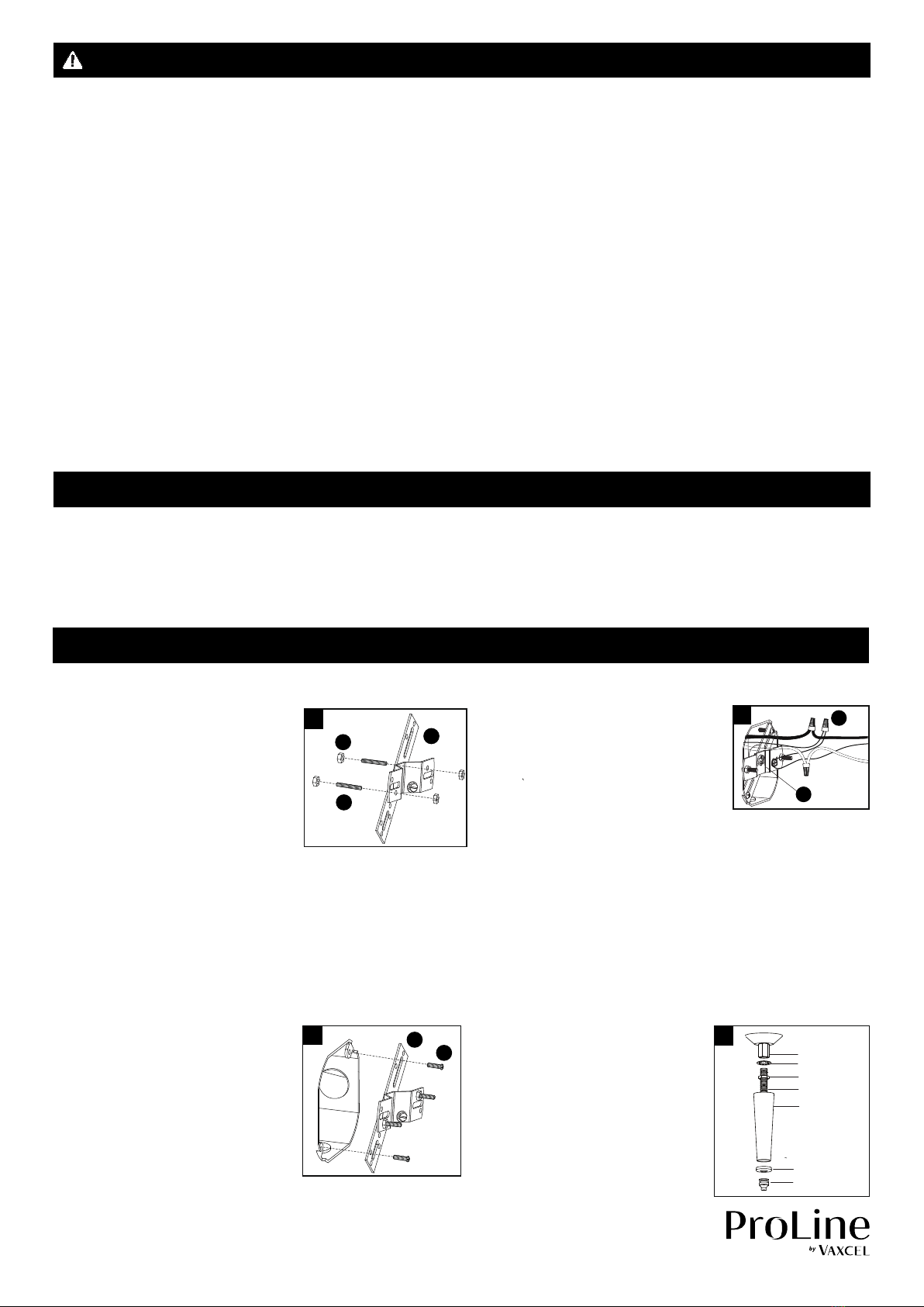
Vaxcel Proline T0429 Instruction manual
Other Vaxcel Outdoor Light manuals

Vaxcel
Vaxcel T0363 Instruction manual

Vaxcel
Vaxcel X0090 Instruction manual

Vaxcel
Vaxcel T0702 Instruction manual

Vaxcel
Vaxcel T0669 Instruction manual

Vaxcel
Vaxcel T0241 Instruction manual

Vaxcel
Vaxcel T0521 Instruction manual

Vaxcel
Vaxcel T0435 Instruction manual

Vaxcel
Vaxcel T0694 Instruction manual

Vaxcel
Vaxcel T0396 Instruction manual

Vaxcel
Vaxcel T0594 Instruction manual

Vaxcel
Vaxcel T0112 User manual

Vaxcel
Vaxcel T0571 Instruction manual

Vaxcel
Vaxcel Lambda T0627 Instruction manual

Vaxcel
Vaxcel T0172 Instruction manual

Vaxcel
Vaxcel T0199 Instruction manual

Vaxcel
Vaxcel T0040 Instruction manual

Vaxcel
Vaxcel T0454 Instruction manual

Vaxcel
Vaxcel Mission T0437 Instruction manual

Vaxcel
Vaxcel T0692 Instruction manual

Vaxcel
Vaxcel T0238 Instruction manual


Popular Outdoor Light manuals by other brands


HEPER
HEPER DOGO Side LW6048.585-US Installation & maintenance instructions

Maretti
Maretti VIBE S 14.6080.04.A quick start guide

BEGA
BEGA 84 253 Installation and technical information

HEPER
HEPER LW8034.003-US Installation & maintenance instructions

HEPER
HEPER MINIMO Installation & maintenance instructions

LIGMAN
LIGMAN BAMBOO 3 installation manual

Maretti
Maretti TUBE CUBE WALL 14.4998.04 quick start guide

Maxim Lighting
Maxim Lighting Carriage House VX 40428WGOB installation instructions

urban ambiance
urban ambiance UQL1273 installation instructions

TotalPond
TotalPond 52238 instruction manual

Donner & Blitzen
Donner & Blitzen 0-02661479-2 owner's manual

LIGMAN
LIGMAN DE-20023 installation manual