manuals.online logo
Brands
  1. Home
  2. •
  3. Brands
  4. •
  5. Vaxcel
  6. •
  7. Outdoor Light
  8. •
  9. Vaxcel Lambda T0627 Instruction manual

Vaxcel Lambda T0627 Instruction manual

Page 1 / 4
220209
ASSEMBLY AND INSTALLATION
INSTRUCTIONS
NOTES: 1. Before installing, consult local electrical codes for wiring and grounding requirements.
2. READ AND SAVE THESE INSTRUCTIONS.
T0627
WARNING:
TO AVOID RISK OF ELECTRICAL SHOCK, BE SURE TO SHUT OFF
POWER BEFORE INSTALLING OR SERVICING THIS FIXTURE.
Wall Mounted Eave Mounted
Sensor
Backplate Light Fixture
Fixture Mounting Screw
Decorative cover
Important to Know:
1. If you are not familiar with state and local electrical
codes, it is recommended that you consult with a
qualified electrician.
2. This fixture requires a 120 VAC, 60 Hz power
source.
3. For general safety and to avoid any possible
damage to the sensor, be sure the power is
switched "off" before adjustment.
Features:
Maximum Wattage: 22 W
Working Temperature Range: -13°F ~ 113°F
1. Energy saving LED fixture.
2. Capable to function as a standalone wall switch light or
as part of a Link Group.
3. When connected to a Link Group, light will receive
signal to turn ON at full brightness automatically when
motion sensor signal is detected and then DIMS light to
low level brightness automatically when motion stops.
5.The wall switch that the light is connected to can be
used to manually override and change functionality
and settings of certain modes.
#8/32X1/2 in
Tools Needed:
1. Phillips-head screwdriver for attaching mounting screws to
mounting strap, mounting bracket and fixture to mounting bracket.
2. 1/8” wide flat-head screwdriver for connecting the source wires
into the wiring terminal station on the mounting bracket.
(2) 1/8" wide Flat-head Screwdriver
Hardware Package (included):
Mounting Screw X2 Fixture Mounting Screw
Mounting Strap
Mounting Screw X2
#6/32 X1/2 in
Mounting Screw X2
#10/24 X1/4 in
Decorative cover
Mounting Strap
Outlet Box
Mounting Screw
Mounting
Bracket
FRONT
L GND N
L GND N
Mounting Screw
Fixture
Mounting
Screw Hole
Terminal
Mounting
Bracket
Screw Hole
Note: Fixture can be wall mounted or eave mounted.
4. When connected to a Link Group, light will receive
signal to remain OFF daylight hours and automatically
turns the light ON during evening hours.
(1) Philip-head Screwdriver
0RGHV of Switch Control Light:
Choose a mode by rotating the control switches on the bottom of the fixture.
(See Fig.2) .
Note: When power is first applied, the light will initially turn on and warm
up for 30 seconds
1. Switch Control Mode (No network,No Linkage)
●In "Switch Control" Mode: when the light switch is turned on, the light turn on at 100% brightness and the pre-selected
CCT color (2700K~5000K).
In "Switch Control" Mode: to change the brightness level of the light, turn the wall switch “OFF" and then back "ON"
twice within 3 seconds. The light will switch from 100% brightness to 30% brightness and pre-selected color
(2700K~5000K) or turn the wall switch OFF for 5 seconds, then turn back ON.
●
2. Motion Link Mode
●In "Motion Link" Mode, the light will turn on at 30% brightness and 2700K CCT
When the light receivesthe motion signal:
Between Dawn to Dusk (daytime hours): the light will remain off.
Between Dusk and Early Evening hour setting on Motion Light: the light will turn on to Low Level setting (30%
brightness and 2700K CCT).
Between Early Evening setting setting on Motion Light and Dawn: the light will turn on to High Level setting (100%
brightness and 5000K CCT). When motion is no longer detected a signal will be sent to return the light to Low Level
settings (30% brightness and 2700K CCT).
At Dawn: the light will turn off.
3. Unlinking from a Link Group
●Press and hold the Link button on the body of light for 3 seconds, the light will flash 3 times to exit linkage.
●In RF Link State, shift the switch from Motion Link Mode to Switch Control Mode, the light will return to Switch
Control function.
Page 2 / 4
Installation Steps
Turn off the power at fuse or circuit box.
Turn on the power at the main fuse or circuit breaker box.
Adjusting the Light Head:
1. Gently grasp the light heads and tilt them up or down, left or right to
adjust the light coverage area. Keep the light heads at least 1˝ (25mm)
away from the sensor. (See Fig. 1)
2. Keep the light heads 30˚ below horizontal to avoid water damage and
electrical shock.
Fig. 1
1. The fixture mounting bracket is pre-assembled on the light fixture. Unscrew both the decorative cover and the fixture
mounting screw in order to remove the mounting bracket.
2. Install the mounting strap to the outlet box with the stamped word “FRONT” facing away from the outlet box, using two
mounting screws that best fit the outlet box. Mounting bracket should sit flush against wall surface when secured.
(Choose one matching pair of suitable mounting screws from the 3 pairs provided).
3. Pull out the source wires from the outlet box. Using a 1/8” flat-head screwdriver connect the black wire from the outlet
box to the "L" interface of the terminal station on the mounting bracket. Connect the white wire from the outlet box to
the "N" interface of the terminal station on the mounting bracket. Connect the Ground wire from outlet box to "GND"
interface of the terminal station on the mounting bracket. Carefully tuck the wires back into the outlet box.
4. Place mounting bracket against the outlet box, insert the mounting bracket screw through the mounting bracket hole,
thread mounting bracket screw into the center hole of the mounting strap. Tighten the mounting bracket screw securely.
5. Attach the backplate of the light fixture to the mounting fixture mounting screw. Then push the decorative cover firmly
into the fixture mounting screw hole on the light fixture. Tighten the fixture mounting screw securely.
6. With silicone caulking compound, caulk completely around where the back plate meets the wall surface.
CAUTION: Be sure to caulk completely where the back plate meets the wall surface to prevent water from
seeping into the outlet box.
220209
Fig.2
2700K 5000K
Motion
Link
Switch
Control
CCT MODE
4.
5.
Manual Override
6. Switch Control Mode
●In "Switch Control" Mode (See Fig.3). Turn the wall switch OFF and back
ON twice within 3 seconds, the light will switch from 100% brightness to
30%brightness and pre-selected CCT (2700K~5000K).
To shift back to 100% brightness and pre-selected CCT (2700K~5000K),
turn the wall switch OFF and back ON twice within 3 seconds again, or
power the switch off for 5 seconds and then turn back.
7. Motion Link Mode
●In "Motion Link" Mode linkage state (See Fig.4). Turn the wall switch
OFF and back ON twice within 3 seconds, the light will stop to receive
motion sensor signal and photo sensor signal from other lights and stay
on at 100% brightness and pre-selected CCT color (2700K~5000K).
●To shift back into the linkage state, turn the wall switch OFF and back
ON twice within 3 seconds, the light will return to 30% brightness and
2700K CCT color. Note if the light is in Motion Link Mode and has not
prior linked to a group, it will remains at 100% brightness and pre-
selected CCT (2700K~5000K).
Page 3 / 4
211221
Troubleshooting
---The light does not come on at all:
1. Make sure the wall switch and circuit breaker are on.
2. Make sure the wiring is correct.
3. Cover the sensor with dark color cloth to verify that the ambient light level is not too high.
---The light comes on for no apparent reason
Re-aim the motion sensor.
2. Decrease the sensitivity setting.
3. Do not use a dimmer or timer to control the light fixture. Replace the dimmer or timer with a standard on/off wall.
---The light flashes on and off:
1. Reposition the bulb away from the motion sensor.
2. Reposition the motion sensor.
3. The motion sensor is in “TEST” mode and warm up.
The following parts are available for re-order if damaged or missing. Call our toll free at 1-800-887-6326.
RF Linking Network Setup
● From all the light units you would like to link, select one as the main unit and the others as sub-units.
● First, setup all of the sub-units by pressing the Link button two times within 3 seconds. The sub-units will flash
once every 1 second (meaning they are waiting to receive a linking signal from the main light).
● Then press and hold the main unit Link button for 5 seconds. The main unit will flash slowly (once every 3
seconds), and when the sub-units have paired with the signal, the sub-units will stop flashing
(confirming they have paired with the main unit). If pairing is unsuccessful, the sub-unit will keep flashing.
● When all the sub-units have stopped flashing, press the Link button on the main unit once to complete the pairing
process (the main unit will then stop flashing).
● After completing the pairing process, any light within the Link group range can send or receive the photo sensor or
motion sensor signal from the other light and respond accordingly.
Note: Maximum number of units per link group is 10 units. The maximum linking distance between lights is
120ft.
Unlinking the unit from the Link Group.
● Press and hold the Link button on the sensor head for 3 seconds, the light will flash 3 times to confirm reset and
remove from the Link Group.
● All lights will need to be reset before setup the Link Group or when adding new light to the Link Group.
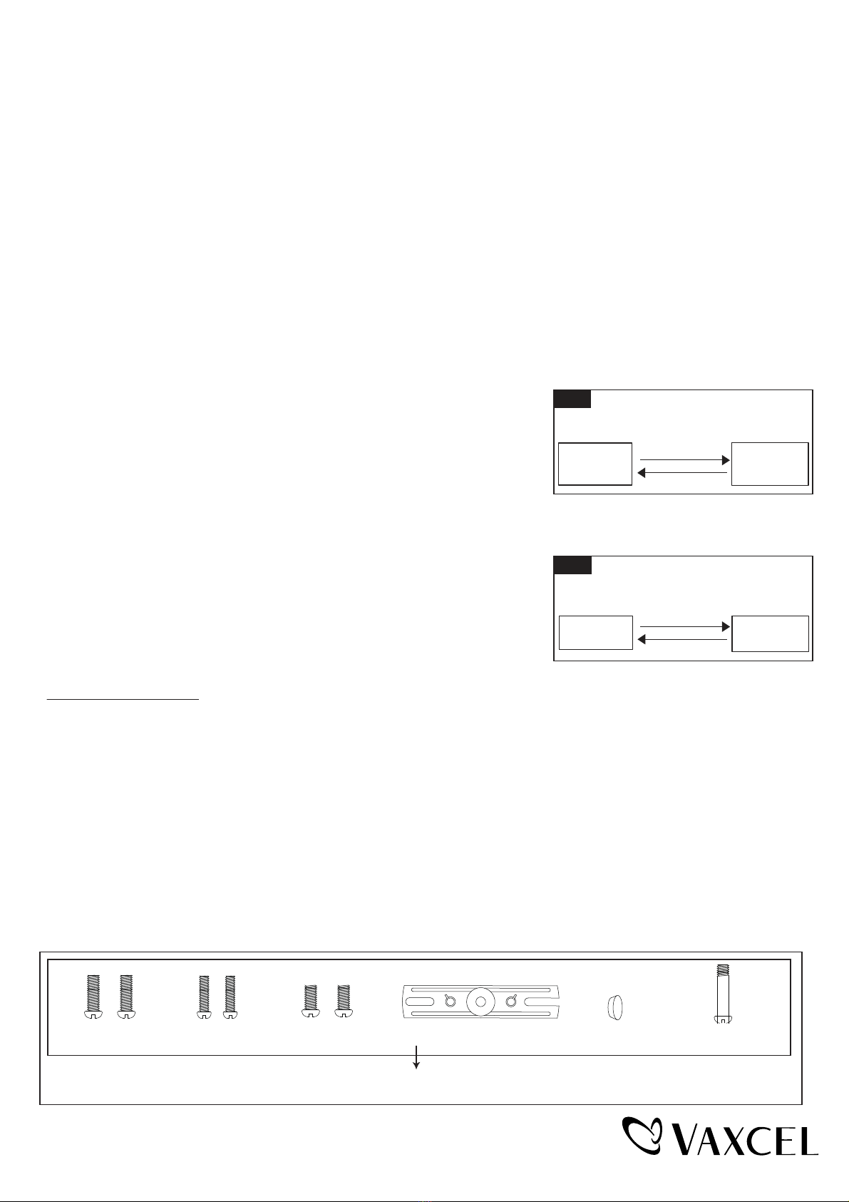
Fig. 3
Full
Brightness
30%
Brightness
Switch Control
Manual Override Operation Diagram
Fig. 4
Motion Link Mode
Manual Override Operation Diagram
Linkage
State
Un-Linkage
State
Mounting Screw X2
#8/32X1/2 in
Fixture Mounting Screw
Mounting Strap
Mounting Screw X2
#6/32 X1/2 in
Mounting Screw X2
#10/24 X1/4 in
Decorative cover
Assembly Kit
6465MM (1 SET)
1.
211221
Page 4 / 4
5-YEAR LIMITED WARRANTY:
All products are warranted to be free of defects in material and workmanship for five (5) years from date of purchase.
This warranty is limited to the correction of any such defect, or the replacement of any such defective item(s), provided
that: (a) we are properly notified and consent to return of the item(s) in question:(b) the item(s) is / are returned with proof
of purchase date; and (c) it is found upon inspection by us that the item(s) is / are defective as noted above. This warranty
does not cover labor costs, consequential damages, nor does it apply to any item(s) that have been improperly installed,
overloaded, altered, or otherwise abused by the customer, its agent(s) or employee(s). Finishes are specially excluded
from the terms of this warranty since they are subject to environmental maintenance deemed beyond our control. Other
than the described obligation, we assume no further liability with respect to the sale or use of our products.We make no
warranty, express or implied, and disclaim any warranty of merchantability or fitness for a particular purpose.
B
A
C
A: 5-1/4"
B:10-1/4"
C: 6"
FCC Statement
This device complies with Part 15of the FCC Rules. Operation is subject to the following two conditions:
(1) this device may not cause harmful interference, and (2) this device must accept any interference received,
including interference that may cause undesired operation.
Changes or modifications to this unit not expressly approved by the party responsible for compliance could void
the user’s authority to operate the equipment.
NOTE: This equipment has been tested and found to comply with the limits for a Class B digital device, pursuant to
Part 15 of the FCC Rules. These limits are designed to provide reasonable protection against harmful interference
in a residential installation. This equipment generates uses and can radiate radio frequency energy and, if not
installed and used in accordance with the instructions, may cause harmful interference to radio communications.
However, there is no guarantee that interference will not occur in a particular installation. If this equipment does
cause harmful interference to radio or television reception, which can be determined by turning the equipment off
and on, the user is encouraged to try to correct the interference by one or more of the following measures:
Reorient or relocate the receiving antenna.
Increase the separation between the equipment and receiver.
Connect the equipment into an outlet on a circuit different from that to which the receiver is connected.
Consult the dealer or an experienced radio/TV technician for help.

Other Vaxcel Outdoor Light manuals

Vaxcel Chatham Instruction manual

Vaxcel

Vaxcel Chatham Instruction manual

Vaxcel T0395 Instruction manual

Vaxcel

Vaxcel T0395 Instruction manual

Vaxcel T0172 Instruction manual

Vaxcel

Vaxcel T0172 Instruction manual

Vaxcel T0363 Instruction manual

Vaxcel

Vaxcel T0363 Instruction manual

Vaxcel T0637 Instruction manual

Vaxcel

Vaxcel T0637 Instruction manual

Vaxcel T0389 Instruction manual

Vaxcel

Vaxcel T0389 Instruction manual

Vaxcel Proline T0429 Instruction manual

Vaxcel

Vaxcel Proline T0429 Instruction manual

Vaxcel T0599 Instruction manual

Vaxcel

Vaxcel T0599 Instruction manual

Vaxcel T0698 Instruction manual

Vaxcel

Vaxcel T0698 Instruction manual

Vaxcel T0414 Instruction manual

Vaxcel

Vaxcel T0414 Instruction manual

Vaxcel T0454 Instruction manual

Vaxcel

Vaxcel T0454 Instruction manual

Vaxcel T0694 Instruction manual

Vaxcel

Vaxcel T0694 Instruction manual

Vaxcel T0551 Instruction manual

Vaxcel

Vaxcel T0551 Instruction manual

Vaxcel T0620 Instruction manual

Vaxcel

Vaxcel T0620 Instruction manual

Vaxcel T0241 Instruction manual

Vaxcel

Vaxcel T0241 Instruction manual

Vaxcel T0130 Instruction manual

Vaxcel

Vaxcel T0130 Instruction manual

Vaxcel T0199 Instruction manual

Vaxcel

Vaxcel T0199 Instruction manual

Vaxcel T0258 Instruction manual

Vaxcel

Vaxcel T0258 Instruction manual

Vaxcel T0692 Instruction manual

Vaxcel

Vaxcel T0692 Instruction manual

Vaxcel T0649 Instruction manual

Vaxcel

Vaxcel T0649 Instruction manual

Vaxcel T0696 Instruction manual

Vaxcel

Vaxcel T0696 Instruction manual

Vaxcel T0595 Instruction manual

Vaxcel

Vaxcel T0595 Instruction manual

Vaxcel T0692 Instruction manual

Vaxcel

Vaxcel T0692 Instruction manual

Vaxcel T0496 Instruction manual

Vaxcel

Vaxcel T0496 Instruction manual

Popular Outdoor Light manuals by other brands

BGS technic 9757 instruction manual

BGS technic

BGS technic 9757 instruction manual

Century FIESTALED COLLANA LUMINOSA quick start guide

Century

Century FIESTALED COLLANA LUMINOSA quick start guide

Thorn ORUS LED installation instructions

Thorn

Thorn ORUS LED installation instructions

Inspire MIRASOL Assembly, Use, Maintenance Manual

Inspire

Inspire MIRASOL Assembly, Use, Maintenance Manual

LIGMAN QU-31392 installation manual

LIGMAN

LIGMAN QU-31392 installation manual

Turnstone Campfire Big Lamp Assembly instructions

Turnstone

Turnstone Campfire Big Lamp Assembly instructions

LIBERTYVILLE LED-1914 installation instructions

LIBERTYVILLE

LIBERTYVILLE LED-1914 installation instructions

Plusrite PLS-30W quick start guide

Plusrite

Plusrite PLS-30W quick start guide

Gainsborough H243 Instructions for use

Gainsborough

Gainsborough H243 Instructions for use

nordlux LISMORE Mounting instruction

nordlux

nordlux LISMORE Mounting instruction

MPOWERD Luci Solar Site instruction manual

MPOWERD

MPOWERD Luci Solar Site instruction manual

ZAZU Lex the lion manual

ZAZU

ZAZU Lex the lion manual

Tala MUSE user guide

Tala

Tala MUSE user guide

LIGMAN VA-20132 installation manual

LIGMAN

LIGMAN VA-20132 installation manual

Brinkmann Solar Gallery Stainless Steel Tier owner's manual

Brinkmann

Brinkmann Solar Gallery Stainless Steel Tier owner's manual

SLV Elektronik THEOS 101 E27 operating manual

SLV Elektronik

SLV Elektronik THEOS 101 E27 operating manual

Hess LED KIT HS.25 manual

Hess

Hess LED KIT HS.25 manual

luxform Chicago manual

luxform

luxform Chicago manual

manuals.online logo
manuals.online logoBrands
  • About & Mission
  • Contact us
  • Privacy Policy
  • Terms and Conditions

Copyright 2025 Manuals.Online. All Rights Reserved.