3
VFLPG/VFL/VTL/VRA-M/ML
Instalacja.
l. Jeżeli nagrzewnica nie jest wykorzystywana w okresie 3 miesięcy, magazynuj ją w suchym pomieszczeniu (maks. 40% RH).
2. Nagrzewnice VFLPG/VFL/VTL są zaprojektownae do montażu isntalacjach kanałowych. Nagrzewnica VRA jest przeznaczona jest
do montażu w centralach wentylacjnych.
3. Powietrze musi przepływać przez nagrzewnicę w kierunku wskazywanym przez strzałkę znajdującą się na pokrywie skrzynki
rozdzielczej.
4. Nagrzewnicę można instalować w kanałach poziomych lub pionowych, ze skrzynką rozdzielczą skierowaną w bok. Niedozwolony
jest montaż ze skrzynką skierowaną do góry lub do dołu.
5. Na otworze wlotowym do pomieszczenia, musi być zamontowana na stałe siatka lub czerpnia powietrza wlotowego,
uniemożliwiająca dotknięcie elementów grzejnych.
6. W pobliżu wylotu powietrza umieścić tabliczkę ostrzegawczą informującą o tym, że wylot powietrza nie może być zakryty.
7. Odległość od (do) nagrzewnicy do (od) łuku kanału, zaworu, filtra itd. powinna wynosić co najmniej tyle, co długość przekątnej
nagrzewnicy, mierzona od narożnika do narożnika po stronie kanału. W przeciwnym
razie istnieje ryzyko, że strumień powietrza przepływający przez nagrzewnicę będzie nierówny, co może spowodować aktywację
wyłącznika przegrzania. Przykład: W kanałach o wymiarach 800 x 400 mm odległość powinna wynosić co najmniej 900 mm (w
przybliżeniu).
8. Nagrzewnica kanałowa może być izolowana zgodnie z obowiązującymi regulacjami dotyczącymi kanałów wentylacyjnych. Izolacja
musi być jednak niepalna. Izolacja nie może zakrywać pokrywy, ponieważ tabliczka znamionowa musi być widoczna, musi być
możliwe zdjęcie pokrywy. Grozi to też przegrzewaniem elementów w skrzynce.
9. Nagrzewnica kanałowa musi być dostępna na potrzeby wymian i przeglądów.
10. Odległość między metalową obudową nagrzewnicy a drewnem lub innymi materiałami palnymi NIE MOŻE być mniejsza niż 100
mm dlatemperatury wykotowej poniżej 50C, nie może być mniejsza niż 300m dla temp. wylotowej od 51 do 120C.
Konserwacja.
l. Nie jest wymagana żadna konserwacja z wyjątkiem okresowej kontroli działania i dokręcenia zacisków zasilania sieciowego co
najmniej raz na rok.
2. Aby utrzymać izolację elementu grzewcego nagrzewnica musi pracować przynajmniej przez 24 godziny po każdych 3 miesiącach.
Przegrzanie.
Nagrzewnica posiada 2 zabezpieczenia termiczne (z których przynajmniej 1 jest ręczny). Jeżeli został aktywowany wyłącznik
przegrzania z ręcznym resetem, należy przestrzegać następujących zaleceń:
l. Pokrywa może być zdejmowana wyłącznie przez elektryków z uprawnieniami.
2. Sieciowe napięcie zasilania musi być wyłączone
3. Ostrożnie zbadać przyczynę aktywacji wyłącznika przegrzania.
4. Po wyeliminowaniu usterki można zresetować wyłącznik przegrzania.
Rozwiązywanie probelmów:
Pełnegrzanie bez regulacji:
-Problem nie jest w nagrzewnicy. Sprawdź regulator zewnętrzny.
Brak grzania:
-Sprawdź podłączenie zasilania na terminalu nagrzewnicy.
-Jeżeli napięcie jest na terminalu sprawdź elementy grzewcze.
-Jeżeli nie ma napięcia, sprawdź czy aktywowało się zabezpieczenie termiczne. Patrz powyżej “Przegrzanie”. W przeciwnym
przypadku problem nie jest w nagrzewnicy. Sprawdź zewnętrzny regulator, bezpieczniki, styczniki, zabezpieczenie przed zanikiem
strumienia, itd.
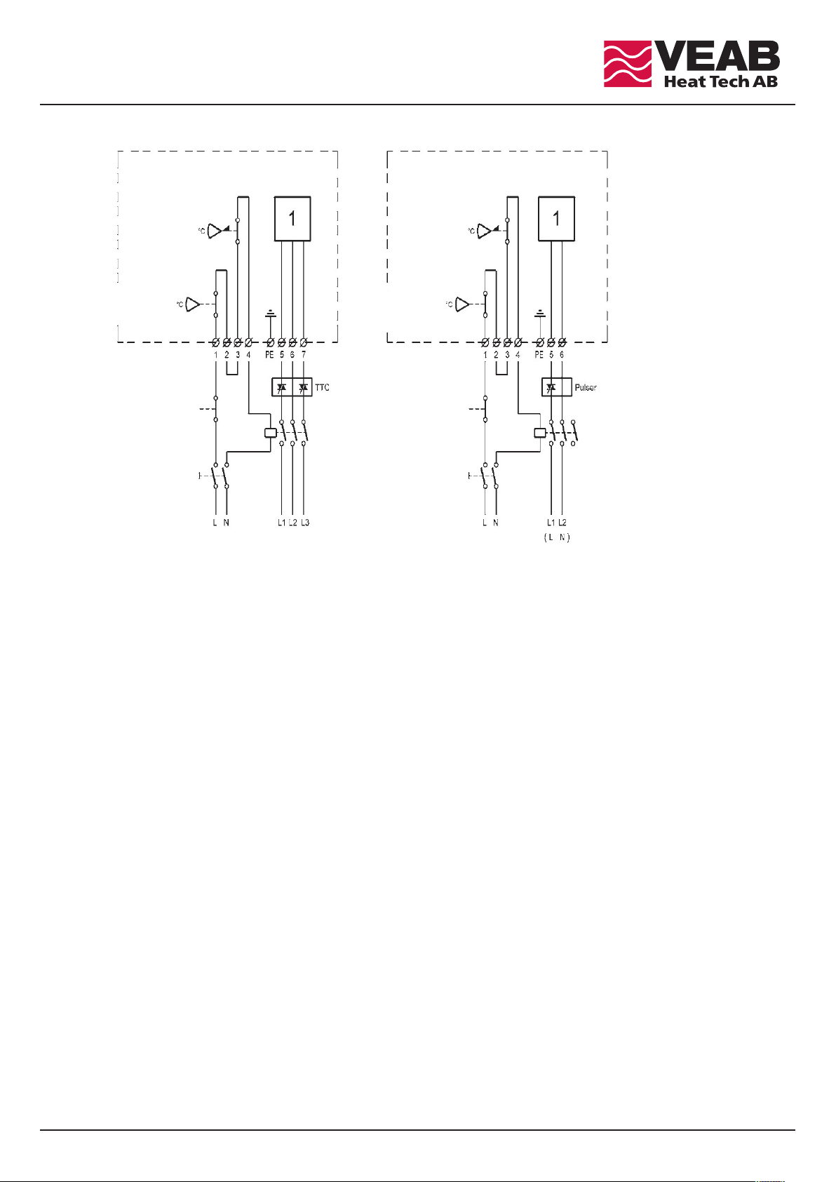
Podłączenie.
1.Nagrzewnica kanałowa jest wyposażona z zabezpieczenie termiczne. Ich ilość i nastawa zależy od wymiarów i intensywności
użytkowania.
2. Nagrzewnica z temperaturą powyżej 50C standardowo jest wyposażona tylko w ręczne zabezpieczenia przed przegrzaniem.
3.Nagrzewnica może być wyposażona w zabezpieczenie termiczne, które ma funkcję stylu przemiennego lub inaczej przekaźnik
może być uwzględniony w podłączeniu. Alternatywnie styki lub styki przekaźnika mogą być wykorzystane w funkcji alarmu do
wskazania aktywacji zabezpieczenia termicznego. Złącza przekaźnika nie powinny być używane do interlockingu, tylko do wskazań.
4.Nie jest rekomendowane, aby funkcja zabezpieczenia przed przegrzaniem była kontrolowana przez obwód elektroniczny. To musi
być tak wykonane, aby odcięcie zasilania nastąpiło jeżeli zadziała zabezpieczenie termiczne.
5. Nagrzewnia może mieć kilka stopni mocy, które są przedstawione na schemacie elektrycznym umieszczonym na wewnętrznej
części pokrywy.