72
2
1.0. INTRODUCTION ...................................................... 3
1.1. GUARANTEE ......................................................... 4
1.2. TRANSPORTATION ................................................... 4
1.3. UNPACKING THE CHAIR .............................................. 4
1.4. MAINTENANCE ...................................................... 5
1.5. VELA TANGO 50 USERMANUAL ...................................... 6
1.6. TECHNICAL DATA .................................................... 7
............................................... 7
1.6.1 Stability and balance.
1.6.2. Disposal . . . . . . . . . ................................................ 8
CONTENTS
VELA Tango 50
Height adjustment Gas, 350N
Seat 44 x 44 cm
Seat depth 37-44 cm
Back 37 x 30 cm
Back tilt -10° / +13°
Armrest size 9 x 30 cm
Armrest spacing 37-51 cm
Armrest height 0-24 cm
Sitting height. Please note that
the height cannot be changed
after delivery
Model 1: 40-55 cm
Model 2: 45-60 cm
Frame 55 x 55 cm
Weight 20 kg
Max. load 125 kg
1.6.1. STABILITY OG BALANCE
The VELA Tango is designed as an everyday chair at home. It is intended for
sedentary work and not as a wheelchair. All movement in the VELA Tango have an
impact on the placement of the centre of gravity.
To increase the safety, we recommend:
• Maximum user weight is 125kg; however the activity level is a significant factor.
A person with very forceful movements using the chair should contact a sales
consultant from VELA/VELA Distributor before purchase
• Do not stand on the chair
• Do not stand on the footring. It is only intended for getting on and off
• The chair is not intended as a wheelchair
• During transportation, the chair should always be locked
1.6.2. RECYCLING
Some of the chair’s material can be recycled. Deliver the chair to VELA’s distributor
or your local recycling installation.
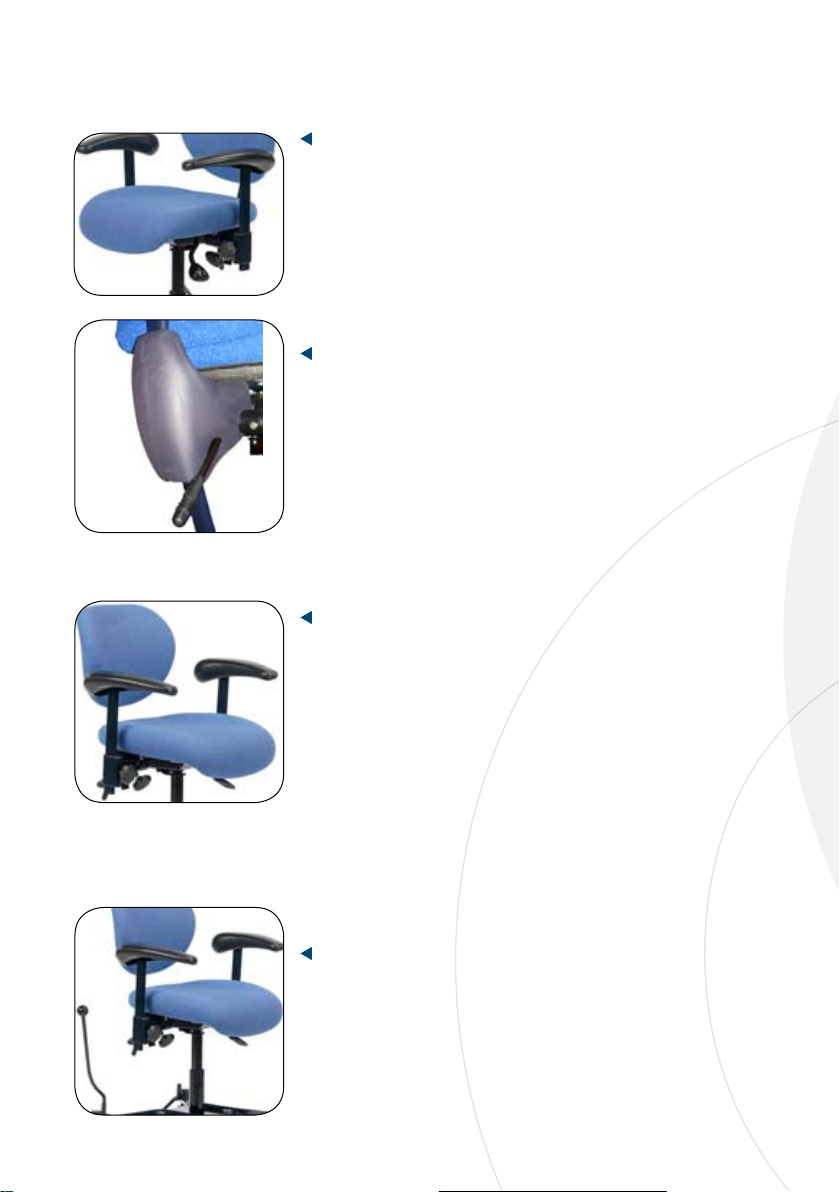
1.5.5. Folding foot ring - Accessory
You can push the folding foot ring up and down just by
pushing the ring with your foot.
1.6. TECHNICAL SPECIFICATIONS
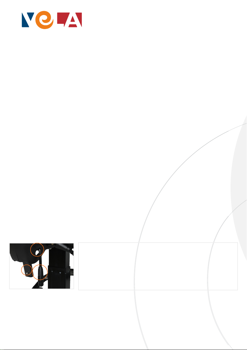
1.
3.
2.
ATTACHING THE BACKREST
The lever (1) for backrest adjustment must be in open position. Press the
locking pin spring and push the backrest arm through the protective cap (2)
and through the hole. Tighten the lever afterwards. The lever for backrest
adjustment should be pulled through the protective cap (3) as shown!
Note: The backrest arm must be pushed through completely so the pin
spring locks the backrest arm. Make sure it cannot be pulled out again.