Velleman VTSSD4 User manual

VTSSD4
MULTI-FUNCTION SMD REWORK STATION 100 W / 600 W
USER MANUAL

VTSSD4
V. 01 –15/05/2014 2 ©Velleman nv

VTSSD4
V. 01 –15/05/2014 3 ©Velleman nv
USER MANUAL
1. Introduction
To all residents of the European Union
Important environmental information about this product
This symbol on the device or the package indicates that disposal of the device after its lifecycle could
harm the environment. Do not dispose of the unit (or batteries) as unsorted municipal waste; it
should be taken to a specialized company for recycling. This device should be returned to your
distributor or to a local recycling service. Respect the local environmental rules.
If in doubt, contact your local waste disposal authorities.
Thank you for choosing Velleman! Please read the manual thoroughly before bringing this device into service. If
the device was damaged in transit, don't install or use it and contact your dealer.
2. Safety Instructions
This appliance is not intended for use by persons (including children) with reduced physical,
sensory or mental capabilities, or lack of experience and knowledge, unless they have been given
supervision or instruction concerning use of the appliance by a person responsible for their safety.
Children shall be supervised to ensure that they do not play with the appliance.
Do not crimp the power cord and protect it against damage.
Warning! If the power cord is damaged, it must be replaced by the manufacturer, its service
agent, or similarly qualified persons in order to avoid any hazard.
Make sure that the available voltage does not exceed the voltage stated in the specifications of this
manual.
Plug the power cord into a suitable, earthed mains outlet.
Risk of electroshock when opening the cover. Touching live wires can cause life-threatening
electroshocks. Do not disassemble or open the housing yourself. Have the device repaired by
qualified personnel.
Do not operate the device with wet hands.
Always disconnect mains power when the device is not in use or when servicing or maintenance
activities are performed. Handle the power cord by the plug only.
Caution! After switching off, leave the power cord plugged in for a few minutes. When you
switch off the unit, the automatic cooling function blows cooling air through the heater pipe for a
short period. This protects the heater from damage and extends its lifetime. Do not disconnect the
mains plug during this cooling process.
Indoor use only. Keep this device away from rain, moisture, splashing and dripping liquids. Never
put objects filled with liquids on top of or close to the device.
Do not use near inflammable products or in explosive atmospheres. Heat can cause fire to
inflammable products even when they are not in sight. Only use in properly ventilated rooms.
Incorrect use may cause fire.
Do not touch the shafts, tips, or hot air gun as this can cause serious burns. Keep the tips and hot
air away from the body, clothes, or other flammable material. Do not aim the hot air gun at the
eyes. Use gloves and/or heat-resistant tools to pick up the PCB assembly to prevent burns. Always
return the irons and gun to their stands between uses; always let the device cool down after use
and before storage.
Place the device on a level, stable, and fire resistant working surface.
Do not inhale solder fumes. The vapours that are released during soldering are harmful. Therefore,
you shall only use the soldering station in well-ventilated areas or under an exhaust hood (solder
fume extractor). Dispose of fume filters and solder residue in accordance with local regulations.
Never use the device on live electronic circuits. Make sure power to the work piece is cut and
capacitors are discharged.
Do not block the hot air gun nozzle. This may cause heat reflection and may damage the heating
element.
Caution! Before the first use, make sure that the pump is unscrewed from the base plate.
Refer to Installation for more information.
Warning! This tool must be placed on its stand when not in use; do not leave the tool unattended
when switched on.

VTSSD4
V. 01 –15/05/2014 4 ©Velleman nv
3. General Guidelines
Refer to the Velleman® Service and Quality Warranty on the last pages of this manual.
Keep this device away from dust and extreme temperatures. Make sure the ventilation openings
are clear at all times.
Protect this device from shocks and abuse. Avoid brute force when operating the device.
Familiarise yourself with the functions of the device before actually using it.
Do not switch the device on immediately after it has been exposed to changes in temperature. Protect the
device against damage by leaving it switched off until it has reached room temperature.
All modifications of the device are forbidden for safety reasons. Damage caused by user modifications to
the device is not covered by the warranty.
This device is designed for soldering/desoldering and hot air SMD rework. Only use the device for its
intended purpose. All other uses may lead to short circuits, burns, electroshocks, crash, etc. Using the
device in an unauthorized way will void the warranty.
Damage caused by disregard of certain guidelines in this manual is not covered by the warranty and the
dealer will not accept responsibility for any ensuing defects or problems.
Keep this manual for future reference.
4. Features
Soldering/Desoldering Function
Isolated power supply: high-quality 32 Vac transformer designed for lead-free soldering/desoldering.
Temperature stability: the tip temperature is accurate to within ± 3 °C (6 °F).
Vacuum switch: suction is controlled by a finger-actuated thyristor circuit conveniently located on the
desoldering handle.
Heater/sensor fail detection: if the sensor circuit fails, the display reads "S--E" and the heater power is cut.
If the heater circuit fails, the display reads "H--E" and the heater power is cut.
Temperature lock feature: you can lock the temperature with a password for use in a production line.
The “zero voltage” switching design protects voltage and current sensitive components (such as CMOS
devices) against overcurrent and transient voltage spikes.
Delayed suction: to prevent solder from clogging up the tip, the delayed switch allows the pump to continue
sucking for 1.5 seconds after you release the control switch.
Lightweight soldering iron: the ergonomic mini handle stays cool and prevents operator fatigue.
Energy saving mode: when the station has been idle for 20 minutes, the energy saving function
automatically brings down the temperature to 150 °C (302 °F). Activating the soldering/desoldering iron
disengages the power saving feature, and the unit immediately returns to the preset temperature. When
the station has been idle for 40 minutes, the device switches off the power to the irons to lower the power
consumption and extend the tip life.
You can use both soldering and desoldering irons at the same time. To save power, you can switch off the
irons individually.
Hot Air Function
600 W heating element
The adjustable temperature allows for safely removing QFP, SOP, PLCC, SOJ… chips. The static-free circuit
design is safe for sensitive elements such as CMOS ICs.
Sensor/pump fail detection: if the sensor circuit fails, the display reads "S--E" and the heater power is cut.
If the pump circuit fails, the display reads "P--E" and the heater power is cut.
Automatic cooling: after switching off the power, the cooling system starts automatically and brings down
the temperature to 100 °C (212 °F) to protect the heating element from burning.
Heating element auto-protection: protects the heating element from overheating, and extends its life.
5. Operating Temperature
The most common soldering alloys used in the electronics industry consist of 60 % tin and 40 % lead. The
operating temperature of this type of solder is detailed below and can vary from manufacturer to manufacturer.
However, to meet RoHS requirements, these solders are no longer allowed and are replaced by lead-free
solders that require a working temperature that is ± 30 °C (54 °F) higher.

VTSSD4
V. 01 –15/05/2014 5 ©Velleman nv
Leaded solder
Lead-free solder
Melting point
215 °C (419 °F)
220 °C (428 °F)
Normal operation
270–320 °C (518–608 °F)
300–360 °C (572–680 °F)
Production line operation
320–380 °C (608–716 °F)
360–410 °C (680–770 °F)
A good joint is assured if the iron's operating temperature is set within the parameters suitable for the type of
solder being used. The solder will flow too slowly if the temperature is too low; if the temperature is too high,
the flux in the solder may burn which will give rise to billowing white smoke. In turn, this will result in a dry
joint or in permanent damage to the PCB.
Important note: Do not use temperatures higher than 410 °C (770 °F) for normal soldering or desoldering
purposes. You can use the device at higher temperatures for short periods, but this will shorten the lifespan of
the tip.
Desoldering
Recommended tip temperatures for desoldering are detailed below. They can vary from joint to joint.
For a small joint
320–360 °C (608–680 °F)
For a larger joint
370–400 °C (698–752 °F)
If the temperature is too low, the solder will flow too slowly, which may cause clogging in the desoldering tip. If
the temperature is too high, you may burn the PCB.
6. Overview
1
power switch
4
desoldering iron connection
2
soldering iron connection
5
desoldering vacuum connection
3
desoldering hot air connection
6
hot air connection
soldering function
7
UP button (▲) to increase temperature
10
heating indication
8
DOWN button (▼) to decrease temperature
11
SET button
9
temperature display
desoldering function
12
UP button (▲) to increase temperature
15
heating indication
13
DOWN button (▼) to decrease temperature
16
SET button
14
temperature display

VTSSD4
V. 01 –15/05/2014 6 ©Velleman nv
hot air function
17
UP button (▲) to increase temperature
21
SET button
18
DOWN button (▼) to decrease temperature
22
UP button (▲) to increase airflow
19
temperature display
23
airflow display
20
heating indication
24
DOWN button (▼) to decrease airflow
7. Installation
7.1 Installing the Fume Extractor
This device comes with a fume extractor. Use this extractor always when soldering or desoldering.
To install the fume extractor, proceed as follows:
1. Make sure that there is a filter in the device (see Replacing Filters).
2. Place the extractor near the working area.
3. Plug the power cord into the back of the fume extractor, and plug the other end into a suitable main outlet.
4. Switch the extractor on.
7.2 Installing the Rework Station
Make sure that the operating voltage of the unit is identical to that of the electrical supply.
In order to protect the pump during transportation, the pump in the machine is fixed by 4 screws in
the base plate. You must unscrew the pump first; otherwise, you may damage the device
permanently.
Always place the irons and the hot air gun in their holders, even if the device is switched off or not
in use. Do not place them on the table or any other surface.
To install the rework station, proceed as follows:
1. Before the first use, remove the 4 screws in the base plate that protect the pump. Refer to the illustration
below:
2. Place the device on a level, stable, and fire resistant working surface.
3. Screw the holder to the station. You can fit the holder on the left or right side:
4. Plug the soldering iron into the soldering iron connection [2] and place the iron in its holder. Note that the
connector has a notch; it only fits in one way. Do not force.
5. Plug the desoldering iron into the desoldering iron connection [4], plug the vacuum tube to the VAC
connection [5], and place the iron in its holder. Note that the connector has a notch; it only fits in one way.
Do not force.
6. Plug the hot air gun into the hot air connection [6], and place the gun in its holder.
7. Make sure that the power switch [1] is in the off position (0).
8. Plug the power cord into a suitable, earthed mains outlet.

VTSSD4
V. 01 –15/05/2014 7 ©Velleman nv
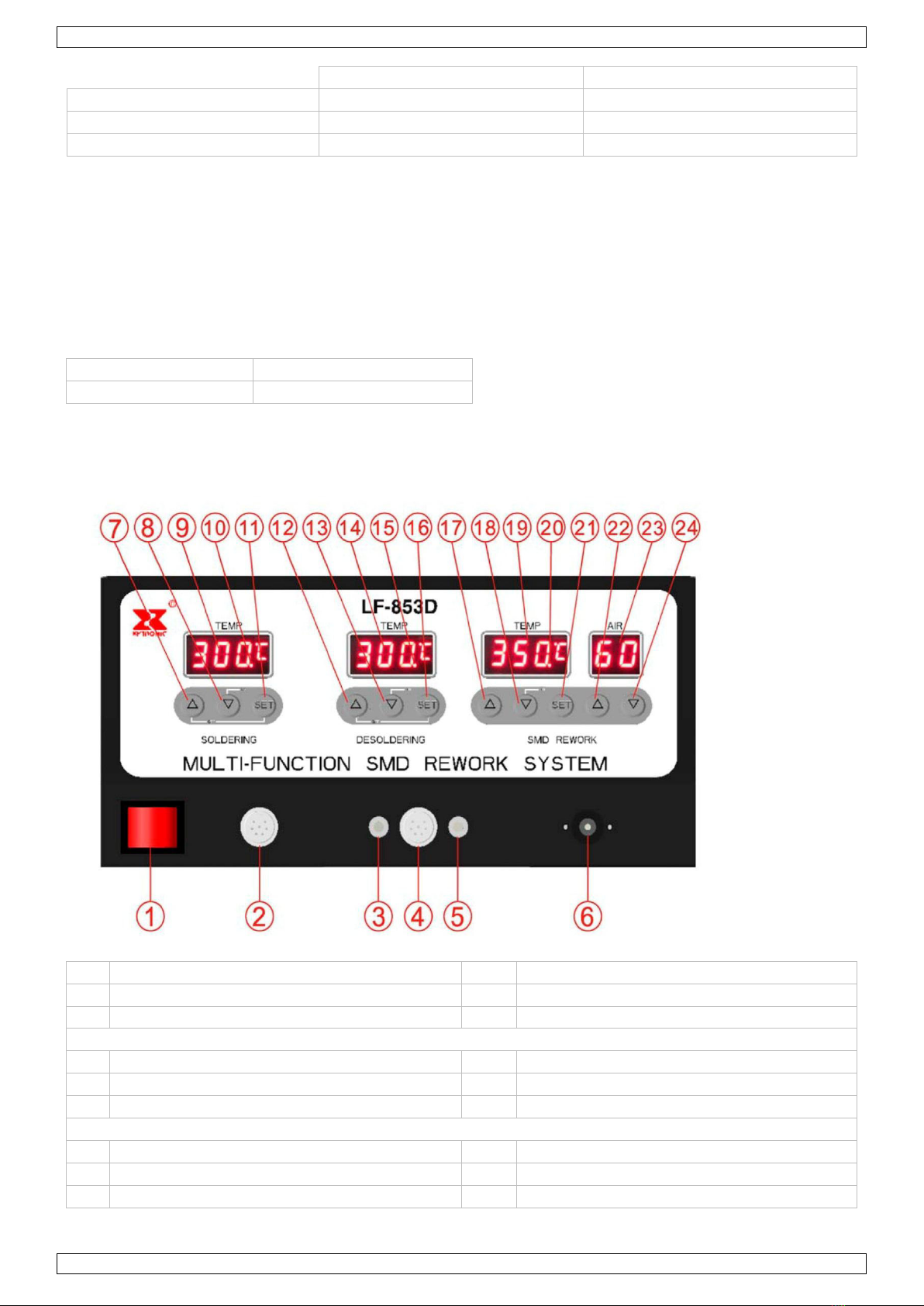
8. Switching On and Off
To switch the device on, set the power switch [1] in the on position (1). The switch lights up. The device
activates all functions (soldering, desoldering, and hot air) and starts heating up. The heating
indications [10,15,20] light up during warming up. The displays [9,14,19] show the temperature.
To switch the device off, set the power switch [1] in the off position (0).
Caution! After switching off, leave the power cord plugged in for a few minutes. When you switch off the
unit, the automatic cooling function blows cooling air through the heater pipe for a short period. This protects
the heater from damage and extends its lifetime. Do not disconnect the mains plug during this cooling process.
Wait until the cooling process has stopped, then disconnect the power plug. The device uses a small amount of
electrical power, even if it is switched off.
Switching off Individual Functions
When you switch on the device, it activates all functions: soldering, desoldering, and hot air. However, to save
power, you can switch off individual functions. Proceed as follows:
1. To switch off a function, press the corresponding SET and ▼buttons simultaneously. For example, to switch
off desoldering, press buttons [16] and [13]. The corresponding temperature display shows “— ——”.
2. To reactivate a function, press the corresponding ▲button.
9. Using the Soldering/Desoldering Iron
9.1 Parameter Settings
The parameter settings for soldering and desoldering are identical. Use the buttons that correspond with the
function that you want to set. For soldering, use buttons 7–11. For desoldering, use buttons 12–16.
1. Switch on the station [1].
2. Press and hold the SET button for at least 5 seconds until “— ——” flashes on the display. Use the
▲button to enter the password “010” (default) and press the SET button to enter the setup menu. An
incorrect password will return the station to normal operation mode (temperature indication).
The display shows “F-0”.
3. Press the ▲ or ▼button to select a mode. If you do not press a button within 15 seconds, the device
returns to normal operation mode.
F-0: exit menu mode
Press the SET button when the display shows F-0 to exit the setup menu and return to normal operation
mode.
F-1: password mode
If password mode is enabled, you cannot change the temperature settings on the station unless you know
the password.
Press the SET button once to enter password mode. Press the ▲or ▼button to switch between 000
(password mode disabled) and 100 (password enabled). Press the SET button to return to the setup menu.
F-2: temperature correction mode
If the displayed temperature deviates from the actual temperature of the tip, you can calibrate the display
here.
Press the SET button once to enter temperature correction mode. Press the ▲or ▼button to enter a
correction factor for the temperature (–99 °C to +99 °C; –178 °F to +178 °F). For example, if the display
shows 300 °C but the actual temperature is only 290 °C, add 10 °C to the shown correction value. If the
current correction value is 00, change it to 10. If the current correction value is –20, set it to –10. If the
current correction value is 20, set it to 30.
A minus sign in front indicates a negative value. Press the SET button to return to the setup menu.
F-3: sleep/power off mode
If you enable the sleep/power off mode, the device automatically lowers the iron temperature after
20 minutes of inactivity (sleep mode). After 40 minutes of inactivity, the power to the iron is shut off
(power off mode).
Note: you can set the sleep/power off mode individually for the soldering and desoldering iron.
Press the SET button once to enter sleep/power off mode. Press the ▲or ▼button to switch between 000
(sleep/power off mode disabled) and 100 (sleep/power off mode enabled). Press the SET button to return
to the setup menu.
In sleep mode, the device lowers the soldering iron temperature to 150 °C (302 °F), and the desoldering
iron temperature to 200 °C (392 °F). The display flashes and shows the lowered temperature.
Note: by default, sleep/power mode is disabled.

VTSSD4
V. 01 –15/05/2014 8 ©Velleman nv
There are 3 ways to exit sleep mode:
oSoldering iron: shake it gently. Desoldering iron: press the suction button on the iron.
oPress any button under the flashing display.
oSwitch the station off and on again.
In power off mode, the display flashes and shows “— ——”. To start the iron again, press the ▼button, or
switch the station off and on again.
F-4: unit of temperature
Press the SET button once to enter temperature mode. Press the ▲or ▼button to switch between °C
and °F. Press the SET button to return to the setup menu.
9.2 Soldering/Desoldering
You can use the soldering and desoldering irons at the same time.
Important note: Do not use temperatures higher than 410 °C (770 °F) for normal soldering or desoldering
purposes. You can use the device at higher temperatures for short periods, but this will shorten the lifespan of
the tip.
Warning! Do not touch the metal parts of the soldering or desoldering iron while the unit is in use or while it is
cooling down, in order to avoid burns.
1. Switch on the station [1].
1. Soldering: press the UP button ▲[7] until the soldering display [9] indicates 250 °C (or 482 °F).
Note: press and hold the ▲or ▼button to increase setting speed.
2. Wait until the temperature is stable: the heating indication [10]blinks.
3. Tin the surface of both the soldering and desoldering tip by applying a new protective layer of solder.
4. When working with a new tip, let the station idle for three minutes at 250 °C (482 °F).
5. Set the irons to the desired working temperature.
6. Always return the soldering irons to their stand between uses.
Important Desoldering Notes
Do not activate the vacuum pump until the solder has melted completely. Move the hot tip around the lead
to melt it, leaving visibly melted solder on the component side of the PCB.
Release the vacuum switch only when the tip is completely solder-free, otherwise the tip may clog.
Add solder to the joint of the component and allow the solder to melt completely for improved desoldering.
Remove the solder collector and clean it after no more than 200 applications. However, daily cleaning is
strongly recommended, especially if the device is used frequently.
Replace the cotton pad in the solder collector and the in-line filter when they start to turn yellow.
Use the included spring wire to clean the tip in case of insufficient suction. Also, check the in-line filters.
Make sure that all filters are in place during operation in order to avoid damage to the vacuum pump.
See Cleaning and Maintenance when you wish to replace the tip.
9.3 Common Causes of Tip Failure
The temperature of the tip exceeds 410 °C (770 °F).
The tip is not sufficiently tinned, or the tip is not tinned when idle.
Lack of flux in soldering, wicking, repair, and touch-up operations.
Wiping the tip on a surface with a high sulphur content or on a dirty or dry sponge.
Contact with organic or chemical substances such as plastic, resin, silicone, and grease.
Impurities in the solder and/or a low tin content.

VTSSD4
V. 01 –15/05/2014 9 ©Velleman nv
9.4 Tip Maintenance
The soldering uses extremely high temperatures. Make sure that the unit is switched off and has cooled
down for maintenance purposes.
Remove the tip and clean it after heavy or moderate use. We recommend cleaning the tip daily if the
station is used frequently. Remove excess solder in the tip retaining assembly to prevent the tip from
clogging.
The supplied soldering and desoldering tips are made of copper covered with a layer of iron. They will retain
their projected life span if used properly.
Always tin the tip before returning it to the holder, before turning off the station, or before storing it for
long periods. Wipe the tip on a wet sponge or use the included tip cleaner before activating the device.
Using excessive temperatures (more than 400 °C or 750 °F) will shorten the life span of the tip.
Do not exercise excessive pressure on the tip or rub the joint with the tip while soldering or desoldering. It
does not improve the heat transfer and may damage the tip.
Apply solder to the joint, not the tip, when soldering. The flux is caustic by nature and eats away the tip.
Never clean the tip with a file or with abrasive materials.
Do not use flux containing chloride or acid. Use only resinous fluxes.
If an oxide film has formed, you can remove it by buffing carefully with a 600–800 grit emery cloth or by
using isopropyl alcohol and then applying a new protective layer of solder.
For new tips: set the temperature to 250 °C (482 °F). When the temperature is reached, tin the tip, and
allow it to idle for three minutes. Then set the desired soldering or desoldering temperature and work
normally.
Important: Remove and clean the tip daily. Remove excess solder from the barrel nut assembly when
installing a new tip, otherwise the tip may be fused to the heating element or to the retaining assembly.
9.5 Possible Causes of Loss of Suction
Use the procedure outlined below to determine whether the loss of suction is due to the tip, to the solder
collector, the tube, or the in-line filters.
Warning! Set the power switch in the off position and allow the iron to cool before executing the procedure
below.
1. Disconnect the vacuum tube from the fitting on the front panel. Place your finger over the hole and depress
the vacuum switch. You should now have a strong vacuum. If not, return the station to the point of sale to
have the pump repaired.
2. Disconnect the in-line filters from the iron assembly. Depress the vacuum switch. Replace the filling of the
in-line filters if there is little suction, or if the filters are discoloured.
3. Remove the solder collector from the desoldering iron assembly. Place your finger over the hole of the
collector and depress the vacuum switch. Clean or replace the collector tube in case of insufficient suction.
4. Depress the vacuum switch and clean the tip with the included spring wire if there is no suction. See
Cleaning Clogged Tips for more information.
10. Using the Hot Air Gun
10.1 Parameter Settings
1. Switch on the station [1].
2. Press and hold the SET button [21]for at least 3 seconds until “— ——” flashes on the display. Use the
▲button [17]to enter the password “010” (default) and press the SET button [21]to enter the setup
menu. An incorrect password will return the station to normal operation mode (temperature indication).
The display shows “F-0”.
3. Press the ▲[17]or ▼[18]button to select a mode. If you do not press a button within 15 seconds, the
device returns to normal operation mode.
F-0: exit menu mode
Press the SET button when the display shows F-0 to exit the setup menu and return to normal operation
mode.
F-1: password mode
If password mode is enabled, you cannot change the temperature and airflow settings on the station unless
you know the password.
Press the SET button once to enter password mode. Press the ▲[17] or ▼[18] button to switch between
000 (password mode disabled) and 100 (password enabled). Press the SET button [21] to return to the
setup menu.

VTSSD4
V. 01 –15/05/2014 10 ©Velleman nv
F-2: unit of temperature
Press the SET button [21]once to enter temperature mode. Press the ▲[17]or ▼[18]button to switch
between °C and °F. Press the SET button [21]to return to the setup menu.
10.2 Operation
Precautions
To extend the life of the heating element in the hot air gun, do not use the device continuously at a low
airflow and a high temperature. Allow the heating element to cool after maximum 20 minutes of usage.
Place the hot air gun back in its stand when not in use.
Make sure that both heater and nozzle are cold before attaching the nozzle.
Warning! High temperature. Both nozzle and airflow are extremely hot and can cause severe burns.
Never touch the nozzle and heater assembly or allow the hot air to blow against your skin. When used for
the first time, the hot air gun may emit some white smoke, but this will soon dissipate.
Caution! Always let the unit cool down after use. After switching off, leave the power cord plugged in for a
few minutes. When you switch off the unit, the automatic cooling function blows cooling air through the
heater pipe for a short period. This protects the heater from damage and extends its lifetime. Do not
disconnect the mains plug during this cooling process.
Do not disassemble the pump. If the pump or other internal components become faulty, stop using the
device immediately. Contact your vendor or its authorised service centre for repair.
Setup
Caution! Do not force the nozzle or pull its edges with pliers. Do not over-tighten the screw.
1. Switch off the device. Wait until the automatic cooling process has stopped, and then disconnect the power
cord.
2. Wait until both heater and nozzle are completely cold.
3. Select the nozzle that matches the IC size.
4. Loosen the screw on the nozzle, slide the nozzle on the heater pipe, and fix it with the screw.
5. Plug in the power cord and switch on the station [1].
6. Press the ▲[17]or ▼[18]button to set the desired temperature.
Note: press and hold the ▲or ▼button to increase setting speed.
7. Press the ▲[22]or ▼[24]button to set the desired airflow.
Note: press and hold the ▲or ▼button to increase setting speed.
8. Wait until the temperature is stable: the heating indication [20] blinks.
QFP Desoldering
1. Hold the nozzle directly over the IC and wait for the hot air to melt the solder.
Caution! Be careful not to touch the IC or the leads with the nozzle.
2. Once the solder has melted, remove the IC using pliers.
3. Clean the remaining solder chips with a wick or the desoldering iron.
QFP Soldering
1. Apply a suitable quantity of solder paste and flux (preferably no-clean) and place the SMD on the circuit
board.
2. Preheat the SMD.
3. Heat the lead frame evenly.
4. When soldering is finished, wash the area with a defluxer.
5. Inspect all joints carefully.
11. Cleaning and Maintenance
11.1 General
Perform only the maintenance as described in this user manual. Contact an authorised dealer or service
agent for any other maintenance or repair.
If the irons, gun, or station become faulty or, for some reason do not operate normally, return them to the
service department of your authorized dealer or service agent.
Clean the outer cover of the irons, gun, and station with a damp cloth and a small amount of liquid
detergent. Never submerge the unit in liquid or allow any liquid to enter the case of the station. Never use
any solvent to clean the case.
Use only original replacement parts.

VTSSD4
V. 01 –15/05/2014 11 ©Velleman nv
Replace cotton filters at least once every 3 to 5 days if you use the station 8 hours per day.
Replace charcoal filters at least every 3 weeks if you use the station 8 hours per day.
Replace the solder collector every 3 to 5 months. Handle the glass collector with care. It is fragile and can
break if you knock it against the desktop.
11.2 Replacing Soldering and Desoldering Tips
Soldering tips can be replaced simply by unscrewing the barrel nut assembly. Turn off the station and allow
it to cool down first. You can damage the soldering station if you switch it on without the tip in place.
After removing the tip, blow out any oxide dust that may have formed in the tip receptacle. Be careful not
to get dust in your eyes. Replace the tip and tighten the screw. You can use pliers to avoid contact with hot
surfaces but use with caution because over-tightening may cause damage to the element or fuse the tip
to the element.
11.3 Cleaning Clogged Tips
To prevent solder from clogging the desoldering tip, clean the desoldering tip after each use with the included
spring wire. This increases the tip life.
Proceed with care when removing the desoldering tip. You may damage the heater when you remove the tip
roughly when it is hot. You may use an anti-rust cleaner if the tip sticks to the heater. Never force.
Warning! To clean a clogged tip, you work on the tip while it is hot. Be very careful not to burn your fingers
when cleaning the tip.
To clean a clogged desoldering tip, proceed as follows:
1. Check if the spring wire (included) can pass through the desoldering tip nozzle.
2. If not, increase the temperature of the heating element so that the clogged solder can melt.
3. Slide the spring wire up and down until the passage is clear.
4. Unscrew the barrel nut assembly.
5. Use a pair of pliers to remove the tip.
6. Reinsert the stainless tube in the heating element to melt the solder. This takes approximately 5 seconds.
7. Remove the stainless tube and shake loose the molten solder.
8. Check if the tip is unclogged, then put it back in place and screw down the barrel nut assembly. Do not
over-tighten.

VTSSD4
V. 01 –15/05/2014 12 ©Velleman nv
11.4 Cleaning the Solder Collector
1. Warning! Switch off the unit and allow it to cool first.
2. Hold the desoldering iron as indicated. Press and turn the red knob on the butt of the iron.
3. Slide out the solder collector. Warning! The solder collector is made of glass and retains heat. Be careful
not to burn your fingers.
4. Point the collector down and shake it gently so that the waste solder falls out. Do this frequently to keep
the station in proper working order.
5. Remove the cooling strip with a pair of pliers.
6. Clean the cooling strip and collector with a wire brush (included).
11.5 Replacing Filters
Notes
Never attempt to wash filters with water, as this reduces their effectiveness and increases risk of damage to
the pump.
Dispose of filters in accordance with local regulations.
Solder Collector Filter
1. Warning! Switch off the unit and allow it to cool first.
2. Hold the desoldering iron as indicated. Press and turn the red knob on the butt of the iron.
3. Slide out the solder collector. Warning! The solder collector is made of glass and retains heat. Be careful
not to burn your fingers.

VTSSD4
V. 01 –15/05/2014 13 ©Velleman nv
4. Disassemble the solder collector.
5. Remove the old filter and replace it with a new one.
In-line Filters
1. Unscrew the in-line filter and pull the two pieces apart.
2. Replace the fillings of both filters.
Fume Extractor Filter
Only use the fume extractor with the filter installed. The filter is located behind a grid that locks it in place.
To install or replace the filter in the fume extractor, proceed as
follows:
1. Make sure that the fume extractor is switched off and that the
power cord is unplugged from the mains.
2. Remove the grid [a] that holds the filter in place: push the
protrusions [b] inward and remove the grid from between the
fume extractor side flaps [c].
3. Remove the old filter [d] and place a new one in front of the
ventilator [e].
4. Place the protective grid back: slide the grid protrusions into
the notches in the flaps and gently click the grid into place.
11.6 Replacing the Hot Air Gun Heating Element
1. Warning! Switch off the unit and allow it to cool first.
2. Loosen the 3 screws [A] on the hot air gun handle and take off the cover.
3. Disconnect the grounding wire and pull the heating element out of the stainless steel tube [B].
Caution! Do not damage or lose the quartz glass and/or insulating mica inside the stainless steel tube.
4. Place a new heating element in the tube, and reassemble in reverse order [C].

VTSSD4
V. 01 –15/05/2014 14 ©Velleman nv
12. Technical Specifications
mains power
230 Vac
max. power consumption
900 W
soldering
power supply
32 Vac / 100 W
temperature range
150–480 °C
desoldering
power supply
32 Vac / 100 W
temperature range
300–450 °C
SMD rework
power supply
230 Vac / 600 W
temperature range
100–480 °C
airflow capacity
1.5 L/min –40 L/min
dimensions
365 x 300 x 150 mm
weight
12 kg
available options
spare desoldering tips
1.2 mm
BITDEST2 (standard desoldering
tip)
1.0 mm
BITDEST3
1.5 mm
BITDEST4
spare filter
FILT/DES2
spare soldering bits
0.2 mm
BITSSC1
0.5 mm
BITSSC2
spare desoldering iron
VTSSD3/DESOL
spare soldering iron
VTSSC7/SP5
spare cleaning pin
VTSSD/SP2
barrel and nut assembly for soldering iron
VTSSC7/SP4
barrel and nut assembly for desoldering iron
VTSSD3/SP2
desoldering iron heater
VTSSD3/SP1
Use this device with original accessories only. Velleman nv cannot be held responsible in the event
of damage or injury resulting from (incorrect) use of this device.
For more info concerning this product and the latest version of this manual, please visit our website
www.velleman.eu.
The information in this manual is subject to change without prior notice.
© COPYRIGHT NOTICE
The copyright to this manual is owned by Velleman nv. All worldwide rights reserved. No part of this
manual may be copied, reproduced, translated or reduced to any electronic medium or otherwise without the
prior written consent of the copyright holder.

Velleman® Service and Quality Warranty
Since its foundation in 1972, Velleman® acquired extensive experience in the electronics world and currently
distributes its products in over 85 countries.
All our products fulfil strict quality requirements and legal stipulations in the EU. In order to ensure the quality,
our products regularly go through an extra quality check, both by an internal quality department and by
specialized external organisations. If, all precautionary measures notwithstanding, problems should occur,
please make appeal to our warranty (see guarantee conditions).
General Warranty Conditions Concerning Consumer Products
(for EU):
• All consumer products are subject to a 24-month warranty on production flaws and defective material as from
the original date of purchase.
• Velleman® can decide to replace an article with an equivalent article, or to refund the retail value totally or
partially when the complaint is valid and a free repair or replacement of the article is impossible, or if the
expenses are out of proportion.
You will be delivered a replacing article or a refund at the value of 100% of the purchase price in case of a flaw
occurred in the first year after the date of purchase and delivery, or a replacing article at 50% of the purchase
price or a refund at the value of 50% of the retail value in case of a flaw occurred in the second year after the
date of purchase and delivery.
• Not covered by warranty:
- all direct or indirect damage caused after delivery to the article (e.g. by oxidation, shocks, falls, dust, dirt,
humidity...), and by the article, as well as its contents (e.g. data loss), compensation for loss of profits;
- consumable goods, parts or accessories that are subject to an aging process during normal use, such as
batteries (rechargeable, non-rechargeable, built-in or replaceable), lamps, rubber parts, drive belts...
(unlimited list);
- flaws resulting from fire, water damage, lightning, accident, natural disaster, etc.…;
- flaws caused deliberately, negligently or resulting from improper handling, negligent maintenance, abusive
use or use contrary to the manufacturer’s instructions;
- damage caused by a commercial, professional or collective use of the article (the warranty validity will be
reduced to six (6) months when the article is used professionally);
- damage resulting from an inappropriate packing and shipping of the article;
- all damage caused by modification, repair or alteration performed by a third party without written permission
by Velleman®.
• Articles to be repaired must be delivered to your Velleman® dealer, solidly packed (preferably in the original
packaging), and be completed with the original receipt of purchase and a clear flaw description.
• Hint: In order to save on cost and time, please reread the manual and check if the flaw is caused by obvious
causes prior to presenting the article for repair. Note that returning a non-defective article can also involve
handling costs.
• Repairs occurring after warranty expiration are subject to shipping costs.
• The above conditions are without prejudice to all commercial warranties.
The above enumeration is subject to modification according to the article (see article’s manual).
Made in Taiwan
Imported by Velleman nv
Legen Heirweg 33, 9890 Gavere, Belgium
www.velleman.eu
Table of contents
Other Velleman Rework Station manuals