10
11
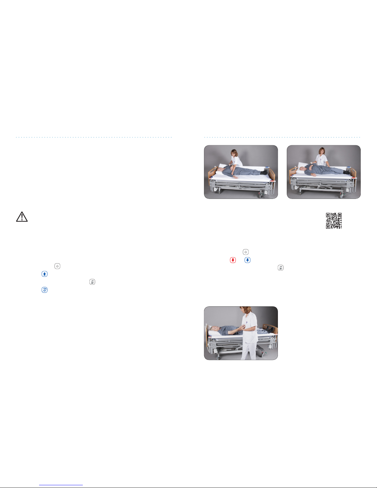
When the bar is up on the side where the turning sheet is being ghtened, the client
will be turned. If, on the other hand, the bar is down on the side where the turning
sheet is being ghtened, the client will be moved towards the edge of the bed. These
fundamental principles provide you with a number of ways to move and/or transfer
clients. See the “How to Use the VENDLET” secon in Part 2 – User Manual for further
details.
The VENDLET can be operated by only one carer.
For safety reasons, clients should not operate the VENDLETs.
Consequently, the hand control should be placed on the outer side of the
headboard or outside the bed before the client is le alone.
Lowering the bed to a very low posion
may leave the actuator bracket very
close to the oor. Consequently, you
should not place your feet under the
actuator ngs.
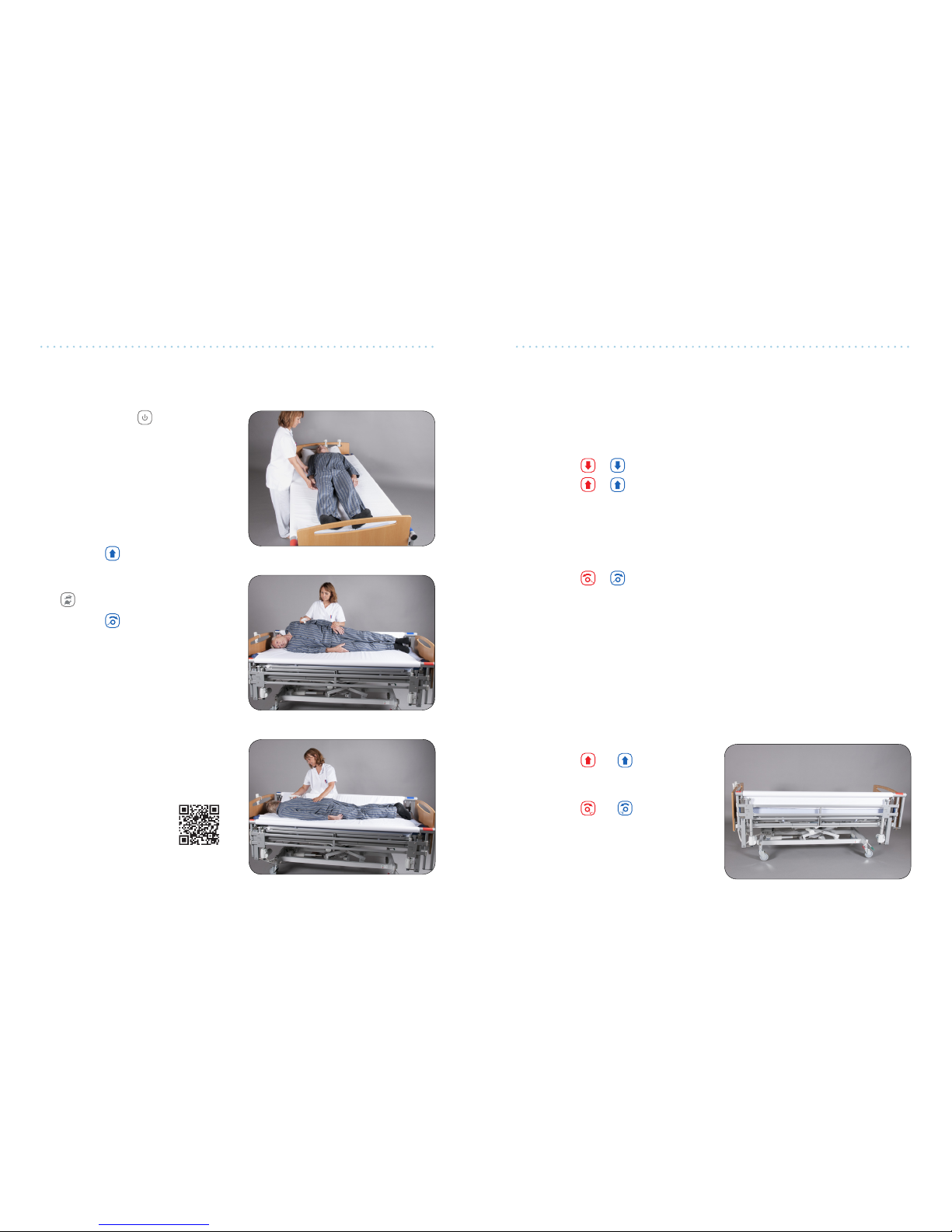
The bed’s lowest height can be restricted on cer-
tain types of beds by mounng height restricon
brackets, see page 38-39.
Height extensions, spacers and brackets:
If parcularly thick maresses are used, it may be necessary to use height extensions,
see page 35. Further, it may be necessary to use spacers if the distance between the
VENDLET system and the maress is insucient, see page 34. Spacers and height
extensions are available as accessories.
Brackets that makes installaon on dierent types of beds easier are available, see
page 38-39.
Wider sheets:
Wider turning sheets and slide sheets are also available if the VENDLET is to be used
on wider beds, see page 22.
Baery backup and under bed light:
Addionally, a baery backup is available to operate the VENDLET without a connec-
on to the supply network. We also provide an under bed light that may be acvated
via the VENDLET hand control, see page 38.
VENDLET are intended for mounng on a wide range of hospital and care beds and
with a wide range of maresses.
The following bed and maress requirements must be met.
1. The bed must meet the established EN 1970, EN 60601-2-38, or EN 60601-2-52
standards.
2. The maximum occupant weight and maximum load requirements of the bed
manufacturer must not be exceeded following the installaon of the VENDLET
system.
3. The bed must have a square steel frame (dimensions H 45-50 mm, W min. 20
mm, L min. 195 cm. without protrusions). The bed width is not crucial as extra
wide turning sheets and slide sheets are available.
1. The maress must meet the requirements of the bed manufacturer and be suit-
able for the bed.
2. The maximum occupant weight requirements of the maress manufacturer must
not be exceeded.
3. Following the installaon of the VENDLET, the distance between the maress
sides and the support bar must be minimum 2.5 cm and maximum 4 cm.
4. If the maress is so and easily compressible, it must be ensured that there is
no crush hazard due to extra compression at the edge of the maress.
5. When alternang air maresses are used, it should be possible to inate the
maress to a rm state before the VENDLET is operated. So maresses will in-
crease the fricon against the maress and create an uneven base for the client
which will be uncomfortable for the client when the VENDLET system is operated.
6. If the client changes maresses, the VENDLET installaon must be evaluated.
A new maress might change the condions and necessitate the reinstallaon of
the VENDLET system.