Voce Freshbrew User manual

1
Part Number: PR14037000
Issue: A – April 2012

Congratulations on your purchase of the VOCE freestanding vending machine from
Crane Merchandising Systems
Introduction / Important Safeguards
1
The following Symbol is used throughout this Operators Manual:
Safety First! Take care, risk of personal injury.
Crane Merchandising Systems accepts no responsibility for damage caused to the equipment
through misinterpretation or misuse of the information contained in this manual.
© Copyright 2012 Crane Merchandising Systems
Introduction
This manual provides you with guidance on the installation, daily operation and basic
maintenance of your VOCE freestanding vending machine. Crane Merchandising Systems always
recommend that a trained technician service its equipment.
Crane Merchandising Systems is committed to continuous product improvement. This means
that the information within this document, although correct at time of publication, is for
guidance only and may be subject to change without prior notice.
Important Safeguards
Always follow these basic safety precautions when operating or maintaining your machine:
1. Ensure that you and anyone who will operate or maintain your machine have this
manual available for quick and easy reference, and read all instructions carefully
before commencing work.
2. Beware of Electricity.Certain maintenance operations require your machine to
remain connected and switched on. Only trained personnel should carry out these
routines, and independently of all other operations. Observation of safe working
practices in accordance with current regulations is necessary at all times.
Important! Unless otherwise specified, always disconnect your machine from the
electricity supply before commencing work.
3. Do not operate your machine if any part is damaged until a service technician has
carried out necessary repairs and ensured that it is safe.
4. Allow your machine to cool before handling or moving.
5. Never immerse your machine in water, or any other liquid and never clean it with a
water jet.
6. If your machine should freeze up, call a service technician to check it before switching
on.

7. Ensure that you are familiar with the most recent Health and Safety at Work and
Electricity at Work Regulations.
Important! This appliance is not intended for use by persons (including children and
the infirm) with reduced physical, sensory or mental capabilities, or lack of experience
and knowledge, unless they have been given supervision or instruction concerning
use of the appliance by a person responsible for their safety. Children should be
supervised to ensure that they do not play with the appliance
Your VOCE machine is for indoor use only and because it is a beverage machine,
should be sited in a clean and hygienic area.
Section 1 – Machine Specifications
3
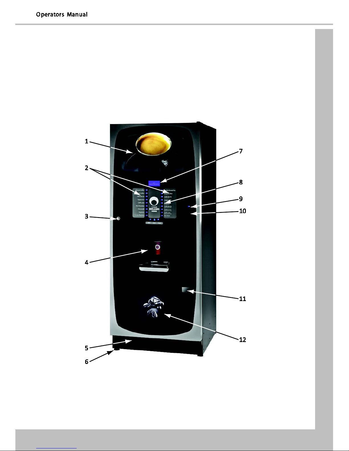
1.3 External Features
Key:
1
Upper Graphic Panel
7
LCD Display
2
Selection Decals
8
Selection Button
3
Door Lock
9
Coin Return Button
4
SureVend™ Sensor
10
Coin Entry
5
Kickplate
11
Coin Return
6
Adjustable Foot
12
Lower Graphic Panel

Section 1 – Machine Specifications
1.4 Internal Features
Key:
1
Main Switch
8
Kick Plate
2
Spray Head
9
Service Keypad
3
Oltre Brewer (Coffee)
10
Cup Turret
4
Oltre Brewer (Tea)
11
Door Locking Mechanism
5
Mixing Station
12
Cup Catcher
6
Brewer Waste Container
13
Surevend Sensor
7
Waste Bucket
14
Drip Catcher Bracket

Section 2 – Installation (Engineers Procedure)
5
Section 2 - Installation (Engineer’s Procedure)
Important! It is essential that the personnel responsible for installing and servicing
your machine, understand the following:
1. The installation and commissioning of your machine should only be carried out by a
trained and authorised service technician.
2. All water and electrical services must be correctly and safely connected.
3. All covers must be replaced correctly and securely and your machine left in a safe
condition.
2.1 Siting your Machine
1. Your machine is for indoor use only. We recommend that it be situated in an area
with an ambient temperature not below 10º C and not exceeding 30º C. Your
machine should be located near the appropriate water and electrical services as
detailed below.
2. Prior to placing your machine in its final location, ensure that there is sufficient access
space available via passageways, stairs, lifts, etc.
3. To ensure adequate ventilation, 100 - 150 mm (4 - 6 inches) clearance must be
allowed between the back of the cabinet and the wall.
4. Open the door using the key provided. Remove transit packing and installation kit.
Check for visual signs of damage which may have occurred during transit. If your
machine is damaged or any parts are missing, you must contact the supplier
immediately.
5. Level your machine in both the front-to-back and side-to-side planes by adjusting the
feet. Ensure that the door opens and closes easily and the lock operates correctly.
2.2 Connecting the Water Supply
1. Your machine should be situated within 1 metre of a drinking water supply from a
rising main, terminating with a W.R.C. approved 15mm compression stop-tap.
N.B. The water supply should comply with both the Statutory Instrument No.1147 -
“Water, England and Wales” and The Water Supply (Water Quality) Regulations 1989.
Water pressure at the stop-tap must be within the limits 2 - 6 Bar (200 Kpa - 600 Kpa).
2. Freshbrew & B2C Machines: If your VOCE machine is fitted with an Oltre brewer, or
CoEx® B2C brewer, then it must be connected to the water supply via a water filter.
This filter must be of food grade quality and able to remove temporary hardness
(scale), heavy metals (lead, copper, iron, and cadmium), chlorine and any organic
pollutants/discolouration.
Crane Merchandising Systems recommend and supply the
Brita AquaQuell water filter.
Section 2 – Installation (Engineers Procedure)
Warning! If your Freshbrew or B2C machine is connected to a water supply and used
without a water filter as specified above, your warranty will be void.
3. Connect the flexi-hose supplied with your machine to the stopcock ensuring that the
seal is fitted correctly. Flush the water supply before connecting the machine.
N.B. When connecting your machine to a water supply always use a new flexi-hose
(such as the one supplied). Never re-use an existing hose.
4. Connect the hose to the inlet valve located on the rear of your machine. Ensure that
the seal is correctly fitted. Ensure that all water supply fittings are tight.
5. Turn on the water supply at the stop tap and check for leaks. Prime the water filter
(where fitted) following the instructions supplied by the filter manufacturer.
2.3 Connecting the Electrical Supply
Safety First!
The electrical safety of this appliance can only be guaranteed if it is correctly and
efficiently earthed, in compliance with National and European regulations on
electrical safety. Always ensure that the earthing is efficient. If you have any doubts,
contact a qualified technician to check the system.
The manufacturer declines all liability for damage resulting from a system which has
not been earthed. On no account should it be earthed only to the water supply pipe.
The appliance must be connected to mains protected by a certified safety switch
(double pole) with a capacity appropriate for the application and in compliance with
National and European regulations on electrical safety.
The appliance must be connected to a 230 Volt 50Hz 13 amp fused switched socket
outlet, installed to the latest edition of the IEE regulations, using a 3 pin BS approved
13 amp fused plug for UK and in compliance with National and European regulations
on electrical safety in other countries
Important: If the mains lead becomes damaged in any way it must be replaced by a
special lead available from the manufacturer.
2.4 Commissioning Procedure
A trained installation engineer must carry out the following procedure before your machine can
be used for the first time. Ensure that the electrical and water services to the machine are
connected correctly. Check for leaks in the water supply.
1. Open the front door of your machine.
2. Ensure that the waste bucket is fitted correctly. Clip the level detector and overflow
pipes correctly onto the rim of the bucket.
3. Cup Turret. Remove the lid and fill the tubes with the correct size cups for the cup
catcher type fitted to your machine. Allow the cups to drop into the tubes directly
from the packaging. DO NOT touch the cups with your hands.

Section 2 – Installation (Engineers Procedure)
7
Important: Do not fill the tube directly above the cup dispense position. Allow the
cup turret motor to rotate a full tube to the cup dispense position when the machine
is powered up. Rotating the cup turret by hand will damage the mechanism.
Note: If you are loading paper cups, first inspect each pack for damage to the cup
rims. Damaged cups must not be used.
4. Turn the machine on with the main switch on the back panel. The cup turret
mechanism will index the first available cups to the dispense position and drop the
cup stack into the cup drop mechanism. Fill the remaining empty cup stack with cups
and replace the lid.
5. All Models: The water inlet valve will open and
the heater tank will start to fill. As the water
heats, ensure that no water overflows from the
heater tank overflow pipe into the waste bucket.
When the machine has powered up, the LCD will
display the message as shown opposite. Check
the system for leaks.
Note! The machine has a safety cut-out which
will only allow the heater tank to fill for a
maximum of two minutes. If after power-up the
heater tank has not filled within this time, the
mains power supply should be switched off and
then on again to reset the heater tank time-out.
After the above message the “Sorry Out Of Service Water Tank Heating” message is
displayed.
6. B2C Models: While the machine is powering up, the LCD will display the Initialising
message. As the machine initialises a small amount of water is pumped through the
system and is discharged into the waste bucket.
7. Before using the B2C machine for the first time it is necessary to purge the water
system to ensure any water left in the system during transport is purged. When the
machine enters standby press button 9 on the Service Keypad fitted inside the door.
The machine will pump approximately 400ml of water through the system
discharging it into the waste bucket.
Important: Should the machine fail to fill correctly or leak, turn off the stopcock and
the power to the machine before investigating the fault.
8. Check the LCD display on the front of the machine to ensure that the water has
heated to the correct temperature and that the machine is in standby mode.

Section 2 – Installation (Engineers Procedure)
A machine set to free vend mode will alternate the messages:
N.B. Messages displayed in standby mode will change depending upon the monetary
device fitted and how the machine is set up during programming.
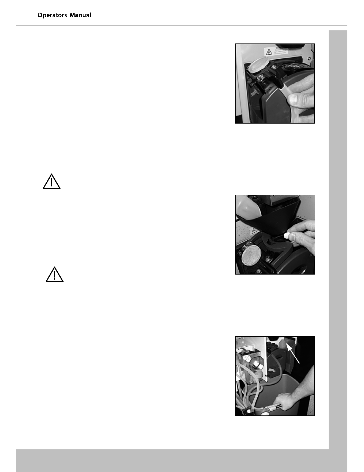
9. All Models: Rotate soluble/freshbrew ingredient canister outlets to upright position.
Remove each canister in turn and fill with the correct ingredient
DO NOT place the canister on the floor or overfill with ingredient.
10. B2C Models: Close the outlet slide to seal the fresh beans canister outlet before
removing the canister from the machine.
DO NOT place the canister on the floor.
Fill the canister with fresh coffee beans. The canister has a capacity of approximately
3.5 kgs. Refit the canister lid and fit the canister into the machine, ensuring that it is
located correctly. Open the outlet slide to ensure correct operation.
N.B. To maintain optimum drink quality, Crane Merchandising Systems recommend
that the bean canister is replenished on a daily basis.
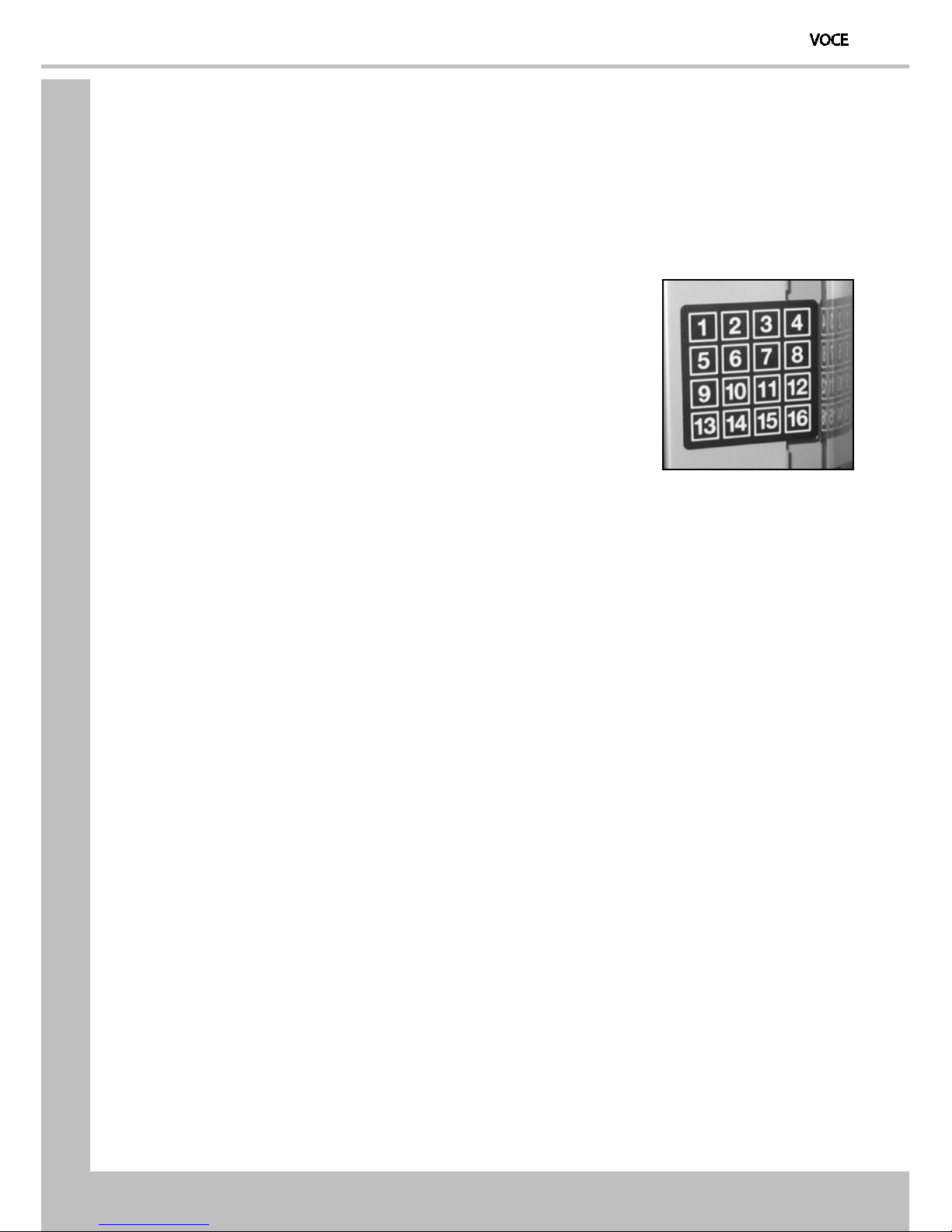
11. Press the Cup Test button (7), located in the Service Keypad on the rear of the door
and ensure that a cup is ejected cleanly from the cup drop unit.
12. Press the Park Head button (8), located in the Service Keypad on the rear of the door
and ensure that the dispense head moves to its fully extended position. Press the
button again to return the dispense head to its correct (homed) position.
13. Freshbrew Models: Ensure the brewer guard and brewer waste container are fitted
correctly. Slide the container into position directly under the brewer.
14. B2C Models: Ensure that the brewer waste container is fitted correctly beneath the
CoEx® brewer unit and tea brewer unit (if fitted).
15. Referring to Sections 6 & 7 of this manual, Programming Mode and Operators
Program, use the menu selections available to programme the required settings for
correct machine operation e.g. drink prices, disable selections, time and date etc.
16. If fitted, check that the coin mechanism and cash box operate correctly. Fill the coin
tubes with correct coinage. Ensure coin return mechanism functions correctly.
17. Operate the machine through its complete range of selections to ensure that each
vend is correctly dispensed.
18. Close the cabinet door. Ensure that the machine is left in a clean and safe condition.
Section 2 – Installation (Engineers Procedure)
9
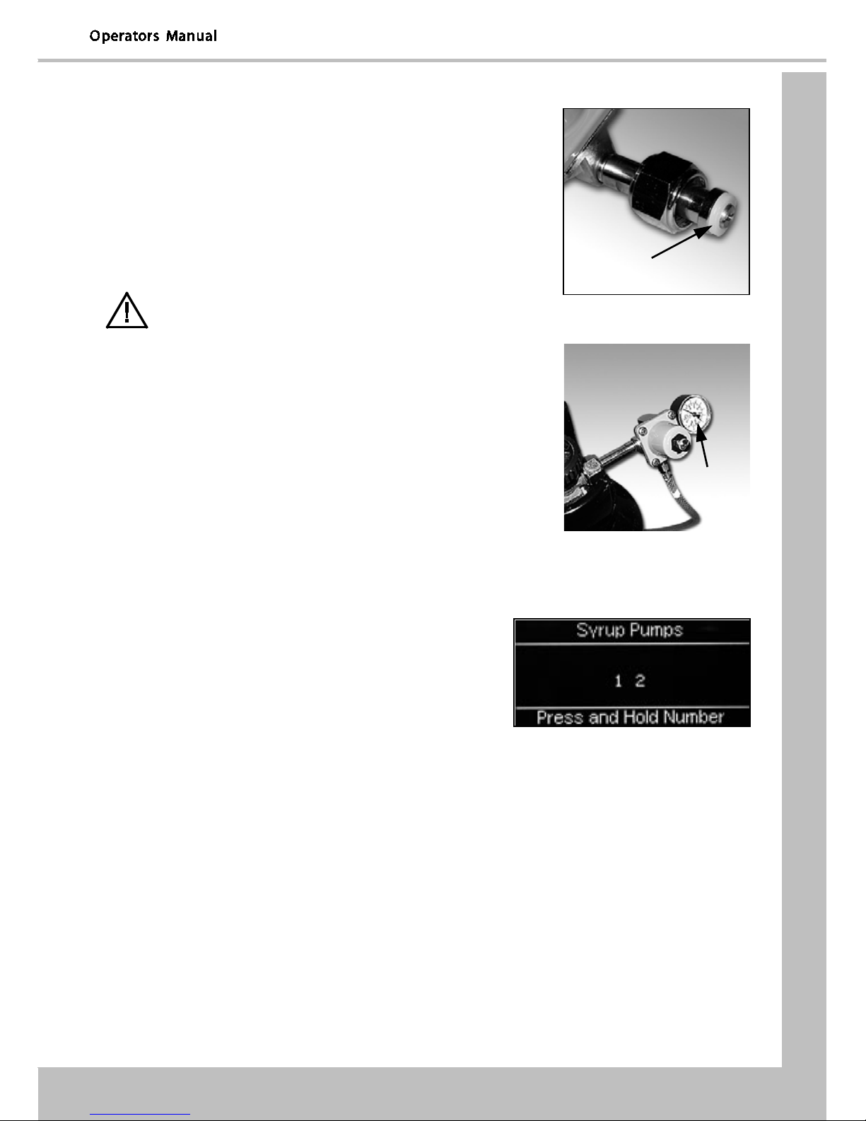
2.5 Setting Up the Carbonator Unit (Where Fitted)
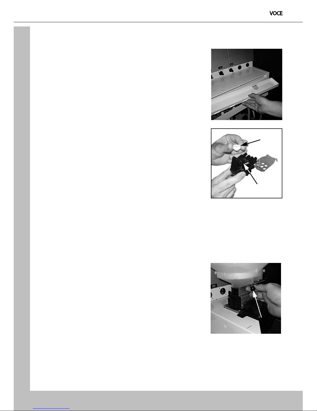
1. Open the cabinet door. Fit the seal (1), provided in the
installation kit, to the regulator as shown in the
photograph. Connect the regulator to the gas bottle.
2. Tighten the locknut. Carefully lift the cylinder into the
machine ensuring that the gas supply pipe is not
trapped or obstructed in any way.
Safety First! The cylinder may be heavy. Always follow
the correct procedure when lifting heavy objects.
3. Secure the gas bottle with the safety chain. Turn on the
gas supply from the bottle and ensure that the
regulator (2) is indicating a gas pressure of 35 PSI.
4. Place the carbonator overflow pipe into the waste
bucket. Fill the carbonator water bath with clean cold
water until it starts to flow from the overflow pipe.
5. Switch on the carbonator unit using the Cold Unit
switch located near the power supply.
6. Place the syrup containers in the bottom right-hand side of the cabinet and insert the
dip tubes into the containers ensuring that the correct flavours correspond to the
drinks displayed on the selection decals.
7. Prime the syrup selections ready for use by
pressing button 13 on the service keypad. The
LCD will display the screen opposite.
N.B. Ensure that the waste bucket is empty and
in place before priming the pumps.
8. To prime syrup pump 1, press and hold button 1 on the drink selection keypad until
the syrup appears from the dispense head. Repeat for syrup pump 2 by pressing and
holding button 2 on the drink selection keypad. Press the X (Exit) key to return the
machine to standby mode. Empty the waste bucket and refit to the machine.
9. Test vend the carbonated drinks to ensure correct operation of carbonator unit.
Check for leaks and ensure that the machine is left in a clean and safe condition.
Close the door.
N.B. If a still unit is fitted ensure that the ingredient timers for syrup drink 1 and 2 are
set to 6 seconds (recommended).
1
2

Section 4 – Cleaning and Re-filling Procedure
Section 4 - Cleaning and Re-filling Procedures
To maintain optimum drinks quality ensure that the machine is cleaned regularly following the
schedule outlined below. Before carrying out the daily cleaning procedure described on the
following pages, it is recommended that you have the following materials to hand
•Bactericidal Cleaner
•De-Staining Agent
•Cleaning Cloths
•Paper Towels
•Small Brush
•Two Large Buckets
•Disposable Gloves
•CoEx® Cleaning Tablets (B2C machines) – See note below
Cleaning Tablets - CoEx® Brewer (B2C Models)
CMS recommends that the brewer cleaning tablets supplied with the machine are used
exclusively for cleaning the CoEx® brewer fitted to VOCE B2C machines. These are available from
your machine supplier in packs of 30 - part number ZC10598000. A detailed procedure for
cleaning this brewer unit is outlined in sub-section 4.7 CoEx® B2C Brewer Unit.
4.5 Daily Cleaning & Filling Procedure
Important: Cleaning and maintenance must be carried out daily. Use the procedure outlined on
the following pages either at the end of the day or at the start of the day before the machine is in
constant use.
4.5.1 Ingredient Canisters - Removal and Clean
1. Rotate canister outlets to upright position and
remove. DO NOT place them on the floor.
2. Clean canisters, paying particular attention to the
area around the canister outlets. Ensure outlets are
dried thoroughly.

Section 4 – Cleaning and Re-filling Procedure
11
4.5.2 Whipper System
1. Twist and remove mixing bowls and steam hoods (a).
2. Remove the dispense pipes (b) from the plastic
dispense block.
3. Turn the whipper base (c) anti-clockwise until it
releases (first click). Remove mixer units (d) and
impeller (e). Turn the whipper base (c) anti-clockwise
again (second d click), pull the whipper base from
the shaft.
4. Clean all of the mixing system parts, including the
steam hoods, mixing bowls and dispense pipes
thoroughly in the diluted bactericidal cleaner solution.
Rinse all components with clean water and dry
thoroughly before refitting to machine.
5. Remove and clean the extract tray (see sub-section 4.5.3 Extract Tray for details).
6. Refit the whipper base. Push the whipper base onto
the motor shaft with the “arrow” symbol lined up
with the motor plate fixing screw (f) as shown. Turn
the whipper base clockwise until it locates with the
first (click) locking position (g). Ensure “0” ring (h) is
correctly located as shown.
7. Refit the impellers to motor shafts ensuring that the
“flat” in the moulding lines up with the flat on the
shaft.
8. Refit mixer unit to whipper base. Turn the whipper
base (i) clockwise until it locks (second click) into
place.
9. Refit steam hoods, mixing bowls and dispense pipes
to mixer units. Refit the dispense pipes to the
dispense block.
e
d
c
g
f
h
i
a
b
Section 4 – Cleaning and Re-filling Procedure
4.5.3 Extract Tray
Remove and clean the extract tray.
4.5.4 Dispense Head
Remove the nut (a) securing the plastic dispense block (b) to the
dispense head assembly. Clean the dispense block.
Rinse the dispense block with clean water, dry and refit.
4.5.5 Ingredient Canisters - Fill and Refit
Fill ingredient canisters as required.
Important: Ensure that the canisters are refitted to correct operating stations.
Weekly; Empty and wash the canisters. Dry thoroughly, refill and refit into the machine
4.5.6 Fresh Bean Canister - B2C machines
If necessary refill the canister. Close the outlet slide (a) before
removing the canister.
Refit the canister. Open the outlet slide.
N.B. To maintain optimum drink quality, CMS recommend that the bean container is replenished
on a daily basis.
a
b
a

Section 4 – Cleaning and Re-filling Procedure
13
4.5.7 Waste Bucket & Syrup Containers
Empty and clean the waste water bucket.
If fitted; check the syrup levels in the syrup containers and
replace if necessary
Clean the base, sides and back of the machine
Refit the waste water bucket into the machine. Ensure that the
level detector and overflow pipes are located correctly in the
bucket.
4.5.8 Dispense Area Components
Remove the cup catcher moulding.
Pull out the two spring loaded pins (a). Remove the drip tray
assembly.
Clean the cup catcher, pipe, drip tray and grille. Rinse and dry.
Wash the drip tray and grille thoroughly.
Wipe clean the interior of the door and the dispense area.
Refit the drip tray, cup catcher and cup stand, ensuring that the
drip tube from the cup catcher moulding is located correctly.
Remove and discard the drip catcher cup (b) and replace with a
new cup.
Note: A 7/9oz cup should be used on all models.
4.5.9 Cup Check
Fill the cup turret as required.
Allow the cups to drop into the tubes directly from the packaging. DO NOT touch the cups with
your hands.
Important: Do not fill the tube directly above the cup dispense position. Allow the cup turret
motor to rotate a full tube to the cup dispense position when the machine is powered up.
Rotating the cup turret by hand will damage the mechanism.
Note: If paper cups are being loaded, each pack of cups must first be inspected for damage to
the cup rims. Damaged cups must not be used.
a
b
Section 4 – Cleaning and Re-filling Procedure
4.5.10 Cash Box
Empty contents from the cashbox, then refit turning the lock to secure.
4.5.11 Test
Using the service keypad located in the rear of the door, proceed as follows:
1. Press the Cup Test button (7) and check that a cup is
ejected correctly.
2. Press the Park Head button (8) to ensure that the
dispense head operates correctly and that the dispense
pipes are fitted correctly.
3. Place a suitable container under the dispense head and
press the Rinse/Flush button (3). The machine will flush
the system. Check that there are no leaks.
4. Press the Test Vend button (6) and using the selection buttons on the front of the
machine, vend a drink to ensure that the machine operates correctly.
Press the “X”(Exit) key to exit menu.
4.6 Oltre Brewer Cleaning Procedure
4.6.1 Daily Cleaning Procedure
Important: Cleaning and maintenance must be completed daily.
Fill a cleaning bucket with hot water and dilute the bactericidal cleaner in accordance with the
manufacturer’s instructions.
Open the door of the machine.
The brewer will always return to its fully open position at the end of the vend cycle. In the
unlikely event that the brewer chamber is closed: -
Press ‘2’ on the service keypad, the brewer will start to move and will stop at the open position.
Disassemble the brewer as illustrated:
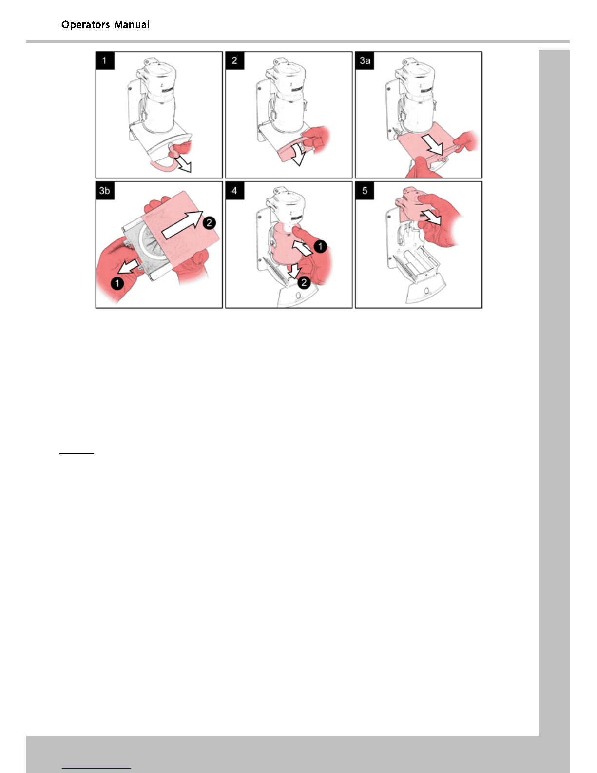
Section 4 – Cleaning and Re-filling Procedure
15
Clean the Oltre brewer chassis and mounting area.
Clean all of the Oltre brewer components.
Rinse all components with clean water, dry then refit to machine.
4.6.2 Weekly Cleaning Procedure
Important: Cleaning and maintenance outlined on the following pages must be carried out on a
weekly basis.
Check that the Oltre brewer(s) are in an open position, if not then press ‘2’ on the service
keypad, the brewer will move and will stop at the open position
Remove the brewer chamber & filter belt assembly, then remove the belt. Clean all components
with the recommended mix of de-staining solution; soak for 5 to 10 minutes.
Rinse all parts thoroughly in clean water & re-assemble into the machine.
Press the service keypad Brewer Clean button (4) and the machine will flush the brewer.
Empty the brewer waste container. Wash the waste container thoroughly.
N.B. If the feature has been turned on when the brewer waste container is emptied the waste
counter must be reset. To reset the waste counter press button 12 on the service keypad, two
audible bleeps confirm that the counter has been reset to zero.
Section 4 – Cleaning and Re-filling Procedure
4.7 CoEx® B2C Brewer Unit
4.7.1 Daily Cleaning Procedure
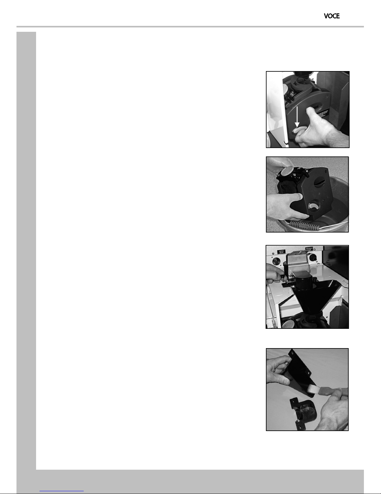
1. Remove the coffee dispense pipe from the brewer outlet.
Lift the green lever (a) and carefully pull the brewer unit
out.
2. Place the CoEx® brewer unit into the diluted bactericidal
solution and clean the unit thoroughly.
Rinse thoroughly with clean water.
3. Remove the B2C coffee chute assembly.
With a clean, dry brush clean the area around and under
the coffee dispense outlets.
4. With a clean, dry brush wipe away any coffee deposits.
Refit the assembly to the machine and secure.
a
Section 4 – Cleaning and Re-filling Procedure
17
5. Refit the CoEx® brewer unit into the machine. Slide the
unit into place until it “clicks” into position. Refit the
coffee dispense pipe.
4.7.2 Weekly Cleaning Procedure
The VOCE has a routine cleaning cycle for the CoEx® brewer, with a warning message to indicate
a clean is “Recommended” or “Required”. If the “Required” message is ignored B2C and
freshbrew drinks cannot be selected until the brewer is cleaned, using the following procedure:
Caution: Ensure that a suitable container is placed under the dispense position. Keep
hands away from the dispense area whilst the cleaning cycle is in operation.
1. Press and release button 11 on the service keypad and
follow the on-screen instructions.
Cleaning Tablets are supplied in packs of 30 - CMS part
no. ZC10598000.)
2. Cleaning cycle lasts approximately 5 minutes and
dispenses approximately 1.8 ltrs of water through the
dispense head.
Safety First! Keep hands clear of the brewer
mechanism during the cleaning routine.
3. On completion the LCD will display the message “Cleaning Cycle Complete”. Press the
X(Exit) key on the drink selection keypad to return the machine to standby mode and
then turn the power off to the machine for 10 seconds.
4.8 Brewer Waste Container and Chute - Daily Clean
1. Remove the brewer waste container and empty the
contents. Push up and remove the waste chute (a).
2. Wash both the container and chute thoroughly and if
necessary sanitise using the diluted bactericidal
solution.
Rinse in clean water then dry both components and
refit in the machine.
a
Section 4 – Cleaning and Re-filling Procedure
N.B. If the feature has been turned on when the brewer waste container is emptied the waste
counter must be reset. To reset the waste counter press button 12 on the service keypad, two
audible bleeps confirm that the counter has been reset to zero.
4.9 Replacing the CO2 Bottle - Where Fitted
For machines fitted with a carbonator unit, it will be necessary for the operator to regularly
check and if necessary, replace the CO2 gas bottle. This will ensure that carbonated vends are
always delivered at optimum quality.
Safety First! The CO2 bottle is filled with gas at a pressure of 800 psi and must be
stored upright and away from sources of heat. In the event of a leak, ventilate the
area in the vicinity of the bottle to remove all traces of gas and contact your supplier.
1. Open the cabinet door and un-hook the safety chain from the gas bottle. Turn off the
gas supply from the bottle.
2. Following correct procedures for safe lifting, lift the
empty cylinder c/w regulator out of the machine.
Carefully undo the locknut using the spanner
supplied. Remove the regulator from the empty
bottle.
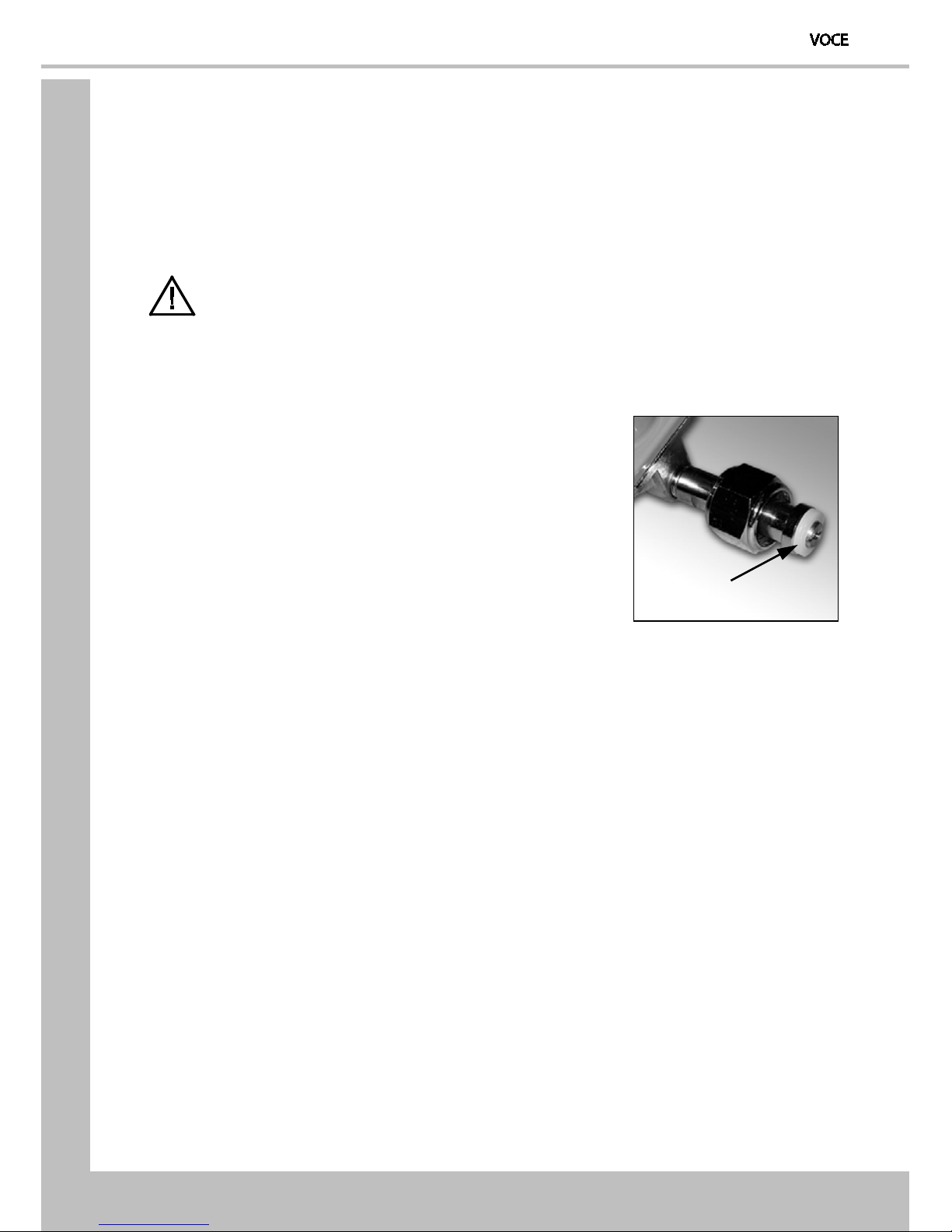
3. Ensure that the seal (1) is seated correctly as shown.
If the seal has been damaged in any way, fit a new
seal.
4. Fit the regulator to the new gas bottle and tighten the locknut. Carefully lift the
cylinder into the machine ensuring that the gas supply pipe is not trapped or
obstructed in any way.
5. Secure the gas bottle using the safety chain. Turn on the gas supply from the bottle
and ensure that the regulator indicates a gas pressure of 35 psi. Close the door and
test vend the carbonated drinks to ensure that the carbonator unit is working
correctly.
1
This manual suits for next models
1
Table of contents
Popular Vending Machine manuals by other brands


Raspberry Pi
Raspberry Pi RASPIVEND quick reference

Unicum
Unicum Foodbox user manual

EVOCA
EVOCA Opera Installation - use - maintenance

Seaga
Seaga Intelligent Inventory Control IQ640 Service and parts manual

N&W Global Vending
N&W Global Vending Canto LB 3600 Installation operation & maintenance

American Games
American Games MAXIM 4200 Operator's manual


