Venture Industries AFC-HT-2-250-025T User manual

OPERATION AND MONTAGE MANUAL NO. 246/U/2015_1
-
ENGLISH
(valid since 29.10.2015)
Venture Industries Sp. z o.o. is not responsible for any damage caused by improper use of the fan and reserves the right to modify this document without informing
the user.
OPERATION AND ASSEMBLY MANUAL
OF AXIAL FAN
42532270-02 AFC-HT-2-250-025T

Axial fan AFC-HT
2 tel. (22) 751 95 50 www.venture.pl fax. (22) 751 22 59
INTRODUCTION
This manual covers fan listed on front page. It is source of information necessary for safe and proper use. Read this manual carefully before any
use of the device, comply with it requirements and keep it in place with easy access for users and service. If case of any
doubts about use of the fan, please contact with manufacturer.
After receiving the device - check
• whether the device is in compliance with order,
• whether the data on the rating plate are the same as desired.
• whether fan was not damaged during transport (e.g. there are no dents/cracks)
• whether a motor documentation (containing manual) is attached
In case of any irregularities, contact with your dealer or Venture Industries Sp. z o.o. service.
1. GENERAL INFORMATION
1.1Information about device
The fan is a not completed machine within the meaning of the Machinery Directive 2006/42/WE (please refer to the manufacturer's
declaration –Appendix E).
Fan is designed for use by trained, qualified adult persons in industrial environment. The fan is not designed for household or similar use.
The device is designed to transport clean air. Do not transport the explosive mixtures, solid elements, liquids, substances that cause
abrasion, chemically reactive compounds. Minimal temperature of transported medium need to be in conformity with motor operating
temperature but not lower than -15°C. Maximum temperature is determined on fan rating plate.
The fan must be protected from the weather (e.g. snow, rain, excessive sun radiation, lightning). The device is not designed to be installed
outdoor. The fan surrounding cannot contain explosive atmospheres, substances causing abrasion, chemically aggressive substances, viscous
substances, liquid, substances with high humidity. Minimal temperature of ambient medium need to be in conformity with motor operating
temperature but not lower than -15°C. Maximum temperature is determined on fan rating plate.
The device must not be exposed to radiation (such as microwave, UV, laser, x-ray).
The impeller has been balanced in accordance with minimum G6.3 class ISO 1940-1, and general construction of the fan in accordance with
cat. BV-3 ISO 14694
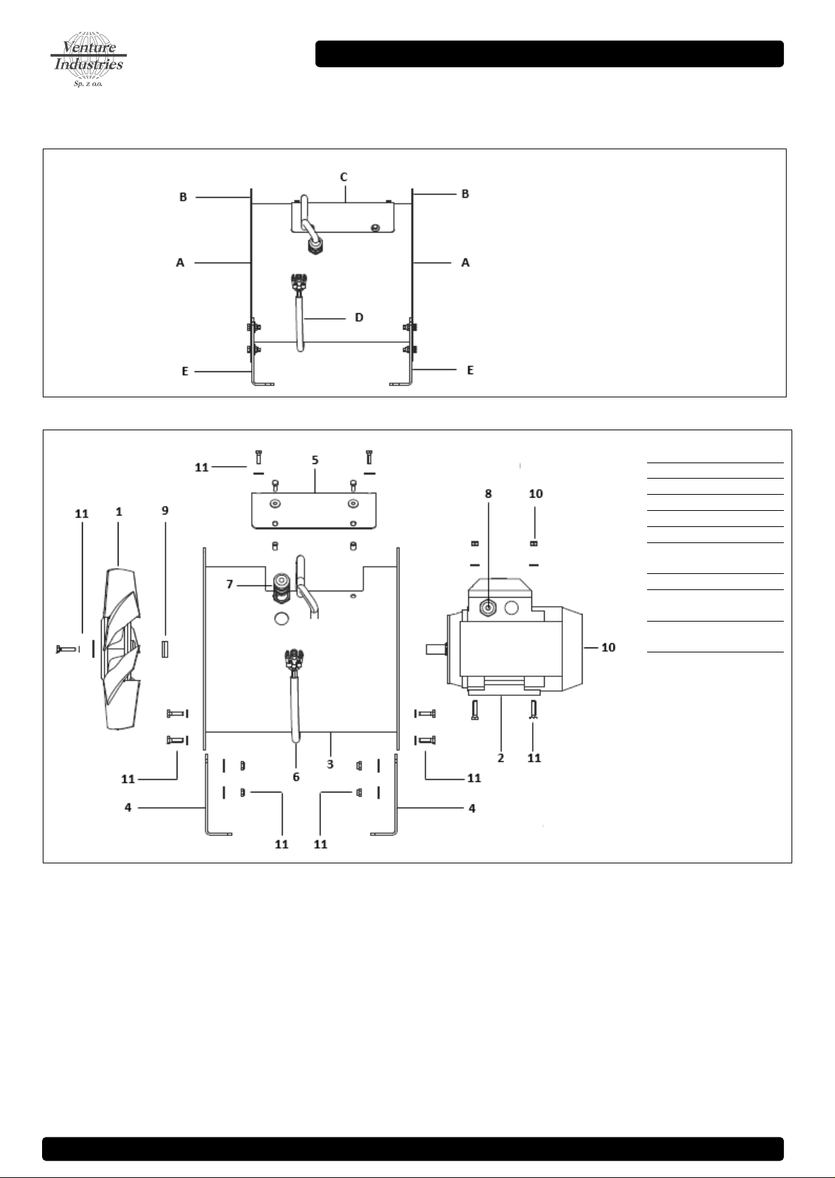
Description of construction of the fan has been included in Appendix A.
Additional information of the fan usage has been indicated on the device. Additional information have been included in Appendix B.
1.2 General risk and guidelines
During entire fan life cycle pay particular attention to the risk and guidelines presented below:
1.2.1 moveable components
The fan is equipped with moveable components (impeller of the device, impeller of the motor). Contact with them may cause
serious injury or death. The fan must not be used if covers (grids) and safety measures against contact with rotating parts have
not been installed.
1.2.2 suction
The fan has high suction power. Clothing, hair, foreign particles, and even body elements can be easily sucked in. It is forbidden to approach
the fan in “loose” clothing or reaching toward inlet of working fan. It need to be ensured, that no foreign body can be sucked in.
1.2.3 thrown elements
The air at the outlet of the fan has high energy. Elements sucked or placed inside the fan can be thrown with a high speed. The fan has stable,
solid construction, but as a result of damage or improper use some parts (elements with high kinetic energy) may be thrown away. Make sure
that before start and during operation of the fan there are no elements, that may be sucked in (pay special attention to fan inlet side) and
there are no person in stream of transported medium (on inlet and outlet side). Do not use fan without proper inlet and outlet covers (grids).
1.2.4 sharp edges
During manufacturing the fan sharp edges was grinded. However the fan may have edges touching which may cause injury.
We recommend the use of relevant protective gloves.
1.2.5. inertness
The fan has a high inertness. In case of no permanent fix turning on the fan will lead to it uncontrolled movement. The unit can be turn on
only after proper installation.
1.2.6 noise
The sound pressure level is dependent on the operation point. Check the sound pressure level and if necessary use silencers and/or individual
protection measures for personnel.
1.2.7 materials
In case of fire or transport of improper medium –fan parts can generate fumes hazardous to health.
1.2.8. environment
The fan can make over and under pressure. In areas where a specified air pressure and the quantity of air are required (e.g. in places with
combustion) make sure that there would be no deficit/excess of air.

MANUAL NO. 246/U/2015_1 (EN)
tel. (22) 751 95 50 www.venture.pl fax. (22) 751 22 59 3
1.2.9 temperature (hot surfaces)
The housing and fan elements take the temperature of transported medium. During work (e.g. as a result of compression
process) the temperature of medium, housing and fan components increase. Electric motor may heat up to high temperatures
(especially when overloaded/overheated). The appropriate steps need to be made to prevent from fire and burns caused of
high temperatures. In case of fire –to extinguish a fire use fire extinguisher approved for electrical equipment and follow
recommendation of fire department.
1.2.10 unexpected start / connecting power supply
● Before undertaking any kind of work on fan (e.g. installation, maintenance and inspection, disassembly), it has to be completely
and reliably disconnected (isolated) from power supply (check there is no voltage). It has to be ensured, that power supply will
not be connected during work on fan and moveable parts are not moving.
The appropriate steps need to be made in order to provide protection against electric shock and to prevent from access to electrical
components by unauthorized person.
●Fan is not equipped with control system –the connecting of power supply causes immediate start-up. The device is not
equipped with system, that would permanently shut it down in case of temporary power supply loss. It has to be ensured, that
any dangerous or unpermitted event does not occur in case of temporary loss of power supply.
●Thermal sensors installed in motor after tripping caused by motor overheat turn back to initial state after cooling down. It has to be ensured,
that any dangerous or unpermitted event does not occur in case of action of thermal sensors and after motor cooling down.
●In case of impeller jamming –its unblocking may cause sudden movement. Appropriate steps should be made in order to avoid impeller
jamming. In case of impeller jamming, fan should be completely disconnected from power supply and inspected (section 5).
●After disconnecting from power supply fan still works for certain time (moveable parts are moving) as a result of energy accumulation.
1.2.11 use
Improper installation and/or use may lead to damage of the device and occurrence of dangerous situation. The unit can by installed,
maintained, dismantled and used only by qualified and authorized personnel, in accordance to safety rules and current regulations in the
country of use (including proper electrical authorization). Personnel need to be familiar with reactions caused by the fan.
Using of fan in dismantled/uncompleted state is forbidden, e.g. with dismantled review cover.
During the works (e.g. maintenance, installation) the fans surrounding should be protected from bystanders approach.
Any modifications of the unit are forbidden. Complicated maintenance work (such as dismantling the motor or impeller) need to be made by
Venture Industries Sp. z o.o. service or with it permission - according to additional guidance. Improper assembly may lead to reduce the fan
parameters, damage the unit and lead to the dangerous situation.
1.2.12 Accumulation of dust
Prevent the accumulation of dust, sediment on and inside the fan. Dirt accumulated on: grids –may reduce the fan parameters; impeller –
may lose it balance; housing and motor –can reduce the cooling; hot surfaces (see 1.2.9) –may ignite.
1.2.13 explosive atmospheres
Contact of the fan with explosive atmospheres cause in ignition. It is forbidden to contact the fan with explosive atmospheres.

Axial fan AFC-HT
4 tel. (22) 751 95 50 www.venture.pl fax. (22) 751 22 59
2. TRANSPORT AND STORAGE
2.1 transport and storage guidelines
• The fan should be transported and stored in original packaging, without excessive shocks. The device must be protected from weather
conditions, transported and stored in dry, well ventilated, and free from substances harmful to the device areas. The fan cannot by transported
and stored in areas with fertilizers, chlorinated lime, acids and other aggressive chemicals. Fan should be protected against foreign body
entrance.
• Protect the fan against damage (including crush). After lifting unit it need to be put slowly.
• The unit should be lifted by housing elements. Do not lift the unit by motor elements (e.g. eye bolt). During lifting the device must remain
stable.
• It is recommended that storage time does not exceed one year. After long storage, before installation check the fan. (section 5). During
storage it is recommenced to manually rotate the impeller (min. 3 turns) once a month.
• Do not approach lifted device. In case of breaking, falling device may cause serious injury or death.
3. ASSEMBLY AND INSTALLATION
3.1 General information
During installation follow the guidelines contained in section 1.2
The fan is a machine not ready for use (within the meaning of the Machinery Directive 2006/42/WE - before use of the device ensure
conformity with requirements of Machinery Directive 2006/42/WE. After installation the device must meet the requirements included in
EN ISO 12100, EN ISO 13857, EN ISO 13850 and EN 60204-1 standards. Additional information is included in Manufacturer Declaration
(Appendix E).
Before installation remove temporary items that protect fan during transport and storage (e.g. box, foil, caps –do not remove any guards) –
Starting the fan with those items could lead to damage of the fan. Make sure that the fan is not damaged.
Ensure that there are no foreign bodies (e.g. mounting elements, tools) inside and near of the unit, that impeller is not blocked, the fan is
properly secured after installation (the review cover is closed, the connecting elements are properly tightened). Technical acceptance should
be carried out in accordance with Appendix C.
3.2 Assembly information
Fan need to by mounted with horizontal orientation of motor shaft (see Fig.1), the construction has to be perfectly horizontal). All assembly
holes, located on the fan foots have to be used. Fasteners secured against self-loosing need to be applied.
Fig. 1
Gdzie:
A –mounting foots
B –Inlet, outlet
C–mounting flange
Supporting construction has to be solid enough in order to carry the weight of the fan and generated vibration (including fan damage). The
fan cannot be exposed to vibration.
Inlet and outlet covers preventing from touching of impeller and touching of motor hot surfaces need to be applied, according to current
edition of ISO 13857 standard. Proper covers preventing from sucking and throwing of elements (see point 1.1.2 and 1.2.3) need to be applied.
The covers need to be made in accordance with IP20 according to EN 60529. If there is still risk of suction foreign elements –apropriate stpes
need to be taken (eg. air filters). Fan covers need to bemade in fixed version.
It is recommended to apply measures minimizing transmission of vibration from/to the fan such as vibro-isolators and flexible connectors.
For fans placed on vibro-isolators connecting on inlet and outlet side should be made in flexible form.
At least 3 inlet diameters distance should be maintained between inlet, outlet and obstacles (e.g. walls, ducts bend). 3 diameters distance is
important for correct fan air vlow, and correct motor cooling.
Keep safe distance between installed device and inflammable elements (attention to hot surfaces of device should be paid).
Measures protecting user from burn by hot elements should be applied.

MANUAL NO. 246/U/2015_1 (EN)
tel. (22) 751 95 50 www.venture.pl fax. (22) 751 22 59 5
3.3 Electrical connection guidelines
The fan and power supply network must be protected in accordance with local law requirements.
Detailed guidelines related to electrical connection are located in motor documentation and on motor markings - those guidelines need to be
applied.
The motor leads , ground (earthing) and PTC thermistor terminals from motor terminal box(conduit box) have been carried out
on the fan housing by a electrical wire. Power supply (L1, L2, L3), ground (PE), thermal sensors (PTC - PTC).
Protection against short-circuits, protection against overload and voltage asymmetry need to be applied. Emergency safety switch (isolator)
near the fan should be applied.
Use appropriate protection against electric shock. Fan need to be connected to grounding system.
Fan grounding terminal (PE - placed on the end of electric wire) need to be connected to grounding system.
Voltage and frequency of supply network cannot exceed those indicated on the fan nameplate.
Eectrical wire need to be placed in way that liquid (e.g. from condensation) does not run over it in the cable gland.
Fan is equipped with type 3xPTC sensors (serial connection): PTC sensor resistance grows rapidly with exceeding of permitted motor
temperature value. Ends of sensors need to be connected to system, which shuts down power supply in case of exceeding permitted motor
temperature.
3.4 Impeller rotation direction
Make sure that after installation and during using the fan the impeller would rotate in correct direction. After mounting fan to proper
construction, with special care taken and in accordance with sector 1 and 4, launch the fan in impulse way (less than 1 second) and check, if
the impeller rotates in correct direction, generating airflow in proper direction. The work with impeller rotating in the wrong direction reduces
fan parameters and may damage it. In case of improper impeller rotation, turn of power supply, wait until impeller stops and swap proper
power supplying wires.
4. USE
4.1 Use guidelines
Make sure that turning on of the fan does not make any hazard for personnel and property. Follow the guidelines featured in section 1.2.
The fan is designed for continuous operations (S1) –too high frequency of starting a fan may lead to motor overheat and damage.
Fan cannot work with voltage, frequency, current higher than shown on the fan nameplate (even if motor nameplate/manual allows it).
Applying of higher frequency may cause motor damage or mechanical damage of the fan.
Voltage regulation is not allowed - it may cause e.g. lack of fan start-up and motor damage.
The device cannot work with current consumption exceeding the value indicated on the nameplate.
In case of activation of any electrical protection, detection of damage, unit must by immediately turn out off use.
The device is adapted to work in certain range of characteristic. Too low volume flow rate of medium, start/work of device with completely
closed inlet and/or outlet may lead to motor overheat caused by current consumption exceeding value on the rating plate (current consumed
by fan grows as resistance of installation increases)
Units work parameters (temperature of medium, ambient temperature, min and max flow rate....) refer to nominal speed.
5. MAINTENANCE, REVIEW
5.1 Maintenance guidelines
During maintenance and review follow the guidelines contained in point 1.2
Fan should be subject of regular review and maintenance (point 5.2).
Maintenance and review of motor need to be overtaken in accordance with motor documentation. Exchange of motor
bearings should be made before the end of current bearing lifetime.
To clean fan use slightly damp delicate material. It is prohibited to use detergents, liquids under pressure and tools that may scratch the unit
surface.
The fan should be turned on at least once a month (minimum couple of impeller turns)
Ensure that there are no foreign bodies (e.g. assembly components, tools) near and inside the fan, the impeller is not blocked, the unit is
clean, dry and secured after maintenance and review. Water excess may be removed with drain valve (if applied). After cleaning finishes, turn
on the fan at max speed for 30 minutes.
During review special attention to the following should be paid:
dust and dirt
Prevent the accumulation of dust/dirt on and inside the fan. Dirt accumulated on: grids –may reduce the fan parameters;
impeller –may lose it balance; housing and motor –can reduce the cooling; hot surfaces –may ignite. Special attention
should be paid to motor cooling impeller and its cover. Reduction of cooling ability may lead to overheat of motor without
working of safety devices.
corrosion
Corrosion of the fan may lead to mechanical damage of it. It is forbidden to use the fan if corrosion appears
overload
Exceeding of nominal current may be caused by improper choice of fan, mechanical damage (e.g. impeller, bearing),
improper electrical connection. Current value should be controlled, and if its growth is noticed, the reason should be
determined and device should be repaired. Current value cannot exceed nominal value.
vibration
Excessive vibration may cause mechanical damage of the fan or in mounting construction. Vibration value should be
controlled, and if its growth is noticed, the reason should be determined and device should be repaired. Initial vibration
value cannot exceed 2,8 mm/s.

Axial fan AFC-HT
6 tel. (22) 751 95 50 www.venture.pl fax. (22) 751 22 59
5.2 Review and maintenance
The set between routine checks and maintenance should be determined by user, based on the observation of unit and specific conditions of
use, in order to include specific work conditions. The set cannot be longer than introduced below
In the case of irregularities the device must be turn off and subjected to review, maintenance and possible repairs / cleaning (when dirt
occurs). Examples of reasons for device to work in emergency mode are given in Appendix D.
People operating the device must be familiar with it normal working conditions. If the fan work differ from it normal working conditions it
need to be turn off from work, inspected and repaired / cleaned.
Recommended daily review, not less frequently than once a week.:
Device is undamaged, stable and works properly
There are not any leaks, smoke from motor
Device does not emit any untypical noise, and does not heat up excessively
Device is clean (external control), corrosion does not occur (external control)
Wires are not damaged
There are no unusual leaks (unit is properly sealed)
Covers are in proper state and clean
Recommended monthly review, not less frequently than once a 3 months.:
Fan current value is not higher than beginning value
The values of generated vibration did not increase (according to beginning value)
Device and covers are clean
Device is clean, filter (if applied) is not clogged.
There are no foreign elements, and loose parts inside fan.
Review once per 3 months, not less than 6 month and 3000 hours of work
Corrosion does not occur (detailed control)
Fasteners state is proper - including those in motor connection box (they are properly tightened)
Security devices are working and set properly, protection against electrical shock is effective.
Motor insulation resistance value is correct
Impeller is able to freely rotate, bearings are not loose and rotation of impeller does not make too much noise.
Structure is not damaged, components are not damaged (e.g. by abrasion)
Minimum in ten years time the impeller need to be controlled due to fatigue strength. At leas once per month drain excess of condensate
through a condensation value.
6. REPAIR, WARRANTY
Use only original spare parts and original accessories. Fan repairs need to be made by Venture Industries Sp. z o.o. service or outside, after
manufacturer permission. Warrantee conditions are described in guarantee card.
7. DISMANTLING AND RECYCLING
Disconnect unit from its power supply, and dismount according to the guidelines from section 1 of this instruction. Therefore, please deposit all
left-over material and packaging in their corresponding recycling containers and hand in the replaced machines to the nearest handler of this
type of waste product.

MANUAL NO. 246/U/2015_1 (EN)
tel. (22) 751 95 50 www.venture.pl fax. (22) 751 22 59 7
Appendix - A (Schematic diagram of the fan / list of devices)
1. General description
A. Inlet, outlet
B. Mounting flange
C. Revision plated
D. Electrical wire
E. Mounting feet
2. List of basic parts
1.
Impeller
2.
Motor
3.
Housing
4.
Mounting foot
5.
Revision plate
6.
Electric wire
7.
Cable gland with
counter nut
8.
Cable gland
9.
Impeller distance
bush
10.
Motor cooling
(motor part)
11.
Connection
elements
Fan housing, revision plate, mounting foots (3, 4, 5) alre made from painted steal. Impeller baldes and hub are made from aluminum. Impeller
distnace bush is made from stainless stel, conection elements are made from galvanized steal. Fan casing is sealed with EPDM tape.
4. Detailed information on the components used and their tightening torque (does not apply to components fitted to motor) are added to
manual as additional documentation or are available on request.

Axial fan AFC-HT
8 tel. (22) 751 95 50 www.venture.pl fax. (22) 751 22 59
Appendix - B (Product indication)
[1] –product full name
[2] –motor type
[3] –motor power
[4] –nominal current
[5] –motor IP class
[8] –nominal voltage
[8] –power supply frequency
[9] –nominal fan speed
[10]- motor insulation class
[11] - weight
[12] –max ambient temperature
[13] –max temperature of transproted medium
[14] –informetion of accordance with ErP Directive (if apply)
[15] –serial number
[16] –Art. No.
Additional information indicated on the device
- arrow informing about correct direction of impeller rotation
- arrow informing about correct air direction
- information about wire marking
- indications related to safe use of device
- marking placed on the motor
- motor nameplate (s)

MANUAL NO. 246/U/2015_1 (EN)
tel. (22) 751 95 50 www.venture.pl fax. (22) 751 22 59 9
Appendix C - (The device receipt form)
Before launch
Check
confirmation
Type and model of fan are in accordance with the order.
The fan is undamaged.
There is no foreign body in inside of fan, and the fan is clean.
The fan was reliably and solidly fixed in workplace.
The fan is properly leveled
Wires are properly tightened.
Ambient temperature and transported medium temperature are compatible with fan nameplate and manual
Proper electrical protection was applied
Grounding of fan was applied.
Network power supply is compatible with fan power supply.
Emergency switch was applied.
Personnel using the fan read and understood the operation and montage manual.
Proper inlet and outlet covers (grids) have been applied
Revision plate is closed (all latches were used) and protected from opening by unauthorized personnel and during worktime
After fan launch (continuous work period minimum 30 minutes)
Readings and set of vibration measurement device has been written (they are available in future)
Value of current for each of phase does not exceed nominal one
Readings and set of current measurement device has been written (they are available in future)

Axial fan AFC-HT
10 tel. (22) 751 95 50 www.venture.pl fax. (22) 751 22 59
Appendix - D (EXAMPLES OF DEVICE FAULTY WORKING)
Symptoms
Possible reason
Excessive vibration or
noise
Used or damaged impeller
Fan levelled in wrong way
Dirt accumulated on impeller caused loss of balance;
Impeller loss of balance
Parts rubbing;
Damage or wear of bearings;
Damage of measurement system, that is responsible for signalization of excessive vibration.
Deformed motor shaft;
Loose of impeller fix screw, impeller is loose on motor shaft;
Loss of balance of motor impeller or damage of motor (wear/damage of bearing)
Motor overload
• Rubbing between fan impeller and housing;
•Damage or wear of bearings;
• Damage of motor windings (overheat, insulation degradation, insulation breakdown etc.);
• Damage of switch or security system;
• Failure of one of supply phases;
• Exceeding of maximum motor speed;
• Too high flow
Failed fan start-up
• Rubbing between fan impeller and housing or foreign body (e.g. tool left after installation);
• Failure of one of supply phases;
• Failure of start-up system
• Reset of security devices has not been made, wrong security device
• Motor connected in wrong way or damaged
Too low voltage supply during start-up
Protective devices
activation during fan
work and overheating
• Excessive start-up time
• Motor overload
Motor launching done too often (overheating, thermal protection sensor activation)
Improper set of protection system ( with PTC)
• Improper cross-section of power supply wires
• Lack of sufficient motor cooling eg. dirt placed on motor cooling impeller (overheating, thermal protection sensor
activation)
Too low flow
Damage of device
Too low power supply frequency
Obstacles in ventilation installation

MANUAL NO. 246/U/2015_1 (EN)
tel. (22) 751 95 50 www.venture.pl fax. (22) 751 22 59 11
ZAŁĄCZNIK - E (Declaration of Manufacturer)
This manual suits for next models
1
Table of contents
Other Venture Industries Fan manuals

Venture Industries
Venture Industries ROOF-H User manual

Venture Industries
Venture Industries RF User manual

Venture Industries
Venture Industries WNF Series User manual

Venture Industries
Venture Industries RF/EC Series User manual

Venture Industries
Venture Industries RBH Specification sheet

Venture Industries
Venture Industries MPB-R Series User manual

Venture Industries
Venture Industries BL User manual

Venture Industries
Venture Industries IBF Series User manual

Venture Industries
Venture Industries RF User manual

Venture Industries
Venture Industries HB User manual